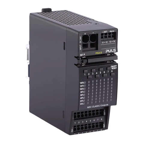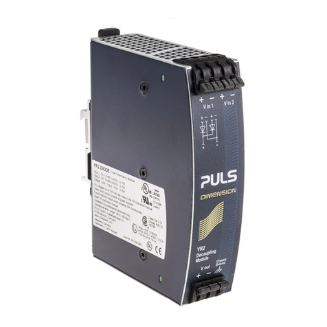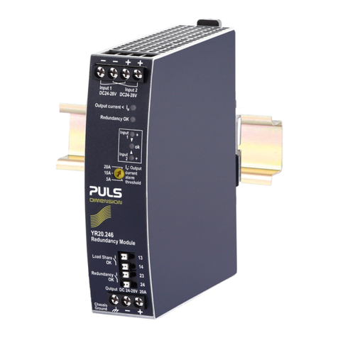
YR20.246
Y-Series 24-28V, 20A, DUAL REDUNDANCY MODULE
INDEX
Page Page
U1. Intended Use .......................................................3
2. Installation Requirements...................................3
3. Input and Output Characteristics .......................4
4. Power Losses........................................................5
5. Lifetime Expectancy and MTBF...........................5
6. Terminals and Wiring..........................................6
7. Functional Diagram.............................................6
8. Front Side and User Elements.............................7
9. “Redundancy OK” Relay Contact .......................8
10. “Load Share OK” Relay Contact .........................8
11. Automated Load Sharing....................................9
12. EMC....................................................................10
13. Environment ......................................................11
14. Protection Features ...........................................12
15. Safety Features ..................................................12
16. Dielectric Strength............................................ 12
17. Approvals.......................................................... 13
18. RoHS, REACH and Other Fulfilled Standards .. 13
19. Physical Dimensions and Weight ..................... 14
20. Accessories ........................................................ 15
20.1. ZM11.SIDE - Side Mounting Bracket........15
21. Application Notes............................................. 16
21.1. Using Only One Input Instead of Both
Channels...............................................................16
21.2. Recommendations for Redundancy.........17
21.3. Inductive and Capacitive Loads................17
21.4. Sidewards Installation Clearances............17
21.5. 1+1 Redundancy up to 10A......................18
21.6. Mounting Orientations ............................19
The information given in this document is correct to the best of our knowledge and experience at the time of publication. If not
expressly agreed otherwise, this information does not represent a warranty in the legal sense of the word. As the state of our
knowledge and experience is constantly changing, the information in this data sheet is subject to revision. We therefore kindly ask
you to always use the latest issue of this document (available under www.pulspower.com). No part of this document may be
reproduced or utilized in any form without our prior permission in writing.
TERMINOLOGY AND ABREVIATIONS
DC 24V A figure displayed with the AC or DC before the value represents a nominal voltage with
standard tolerances (usually ±15%) included.
E.g.: DC 12V describes a 12V battery disregarding whether it is full (13.7V) or flat (10V)
24Vdc A figure with the unit (Vdc) at the end is a momentary figure without any additional
tolerances included.
may A key word indicating flexibility of choice with no implied preference
shall A key word indicating a mandatory requirement
should A key word indicating flexibility of choice with a strongly preferred implementation
1+1 Redundancy Use of two identical power supplies in parallel to provide continued
operation following most failures in a single power supply. The two power
supply outputs should be isolated from each other by utilizing diodes or
other switching arrangements. E.g. two 10A power supplies are needed to
achieve a 10A redundant system.
AC
DC
AC
DC
Load
+
-
IN 1
OUT
IN 2
May 2017 / Rev. 1.3 DS-YR20.246-EN All parameters are typical values specified at 24V, 20A output current, 25°C ambient and
after a 5 minutes run-in time unless otherwise noted.
www.pulspower.com Phone +49 89 9278 0 Germany
2/19
