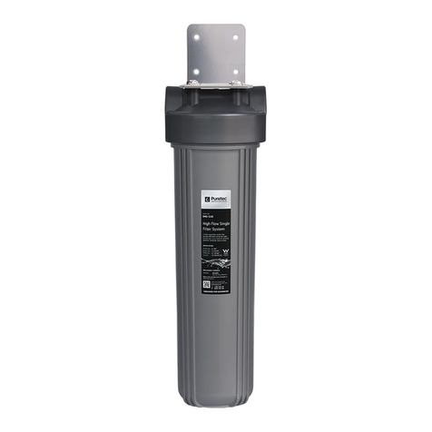
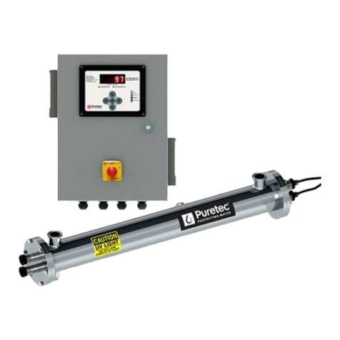
Puretec WU-UV Series User manual
Other Puretec Water Filtration System manuals

Puretec
Puretec RO SERIES User manual

Puretec
Puretec PureMix Z2 User manual
Puretec
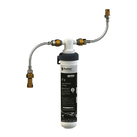
Puretec NTR-E3 Series User manual
Puretec
Puretec Z1-MW-K User manual
Puretec
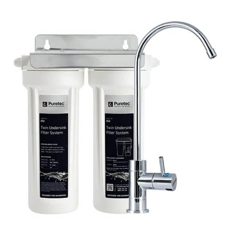
Puretec ES2 Series User manual
Puretec
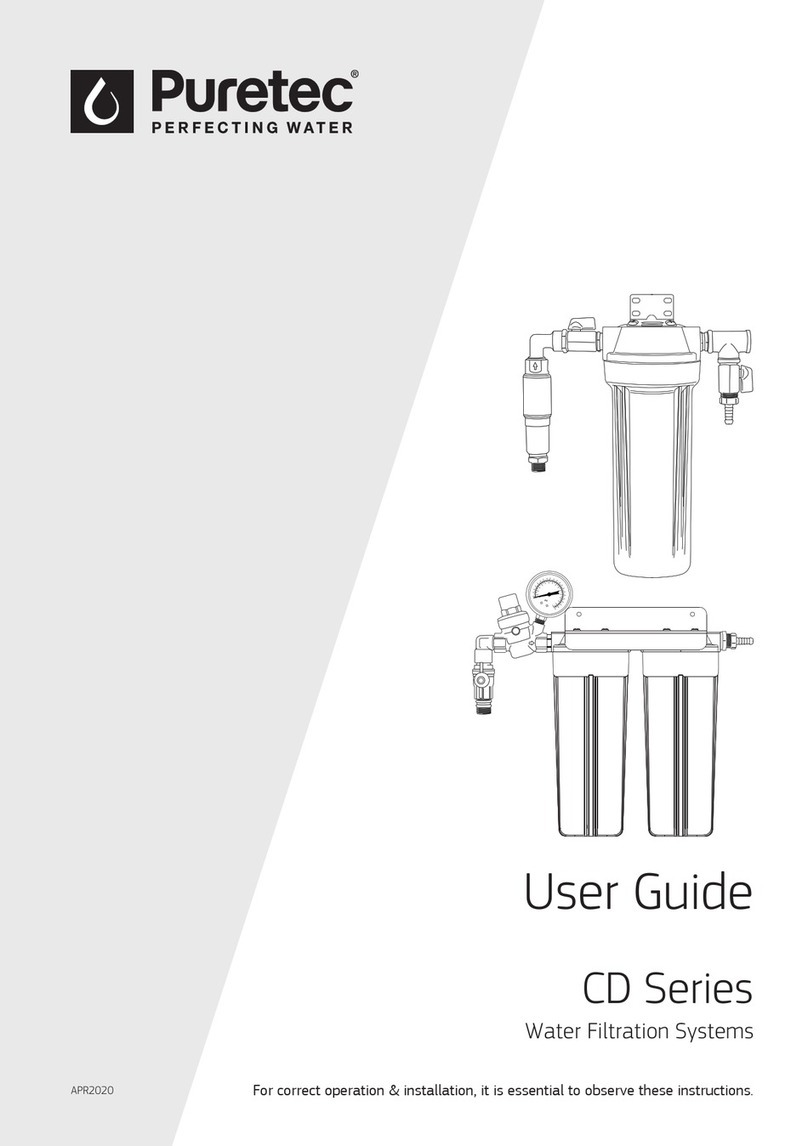
Puretec CD Series User manual
Puretec
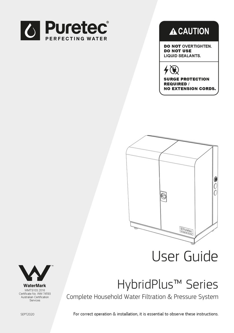
Puretec Hybrid-P9 User manual
Puretec
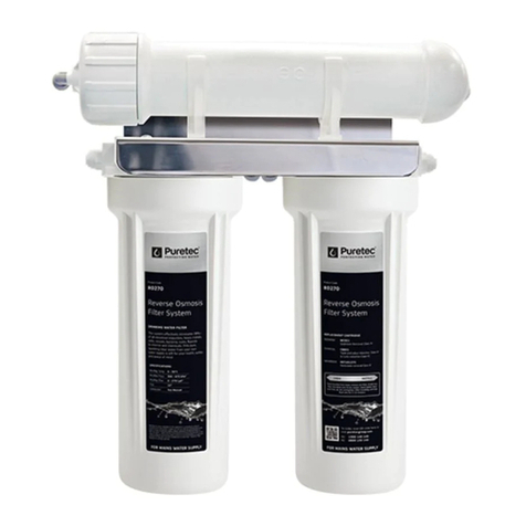
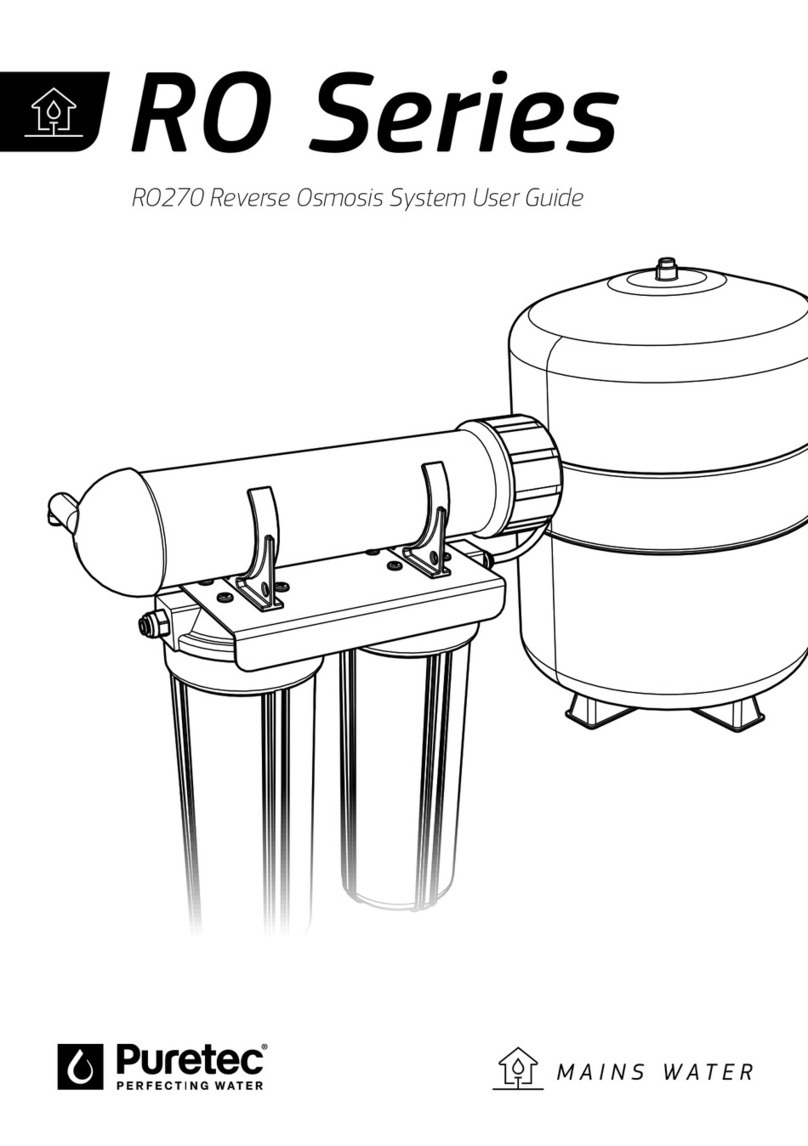
Puretec RO270 User manual
Puretec
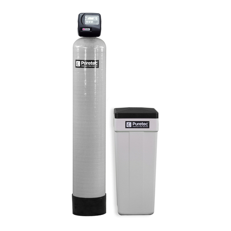
Puretec MUL-E1 Series User manual
Puretec
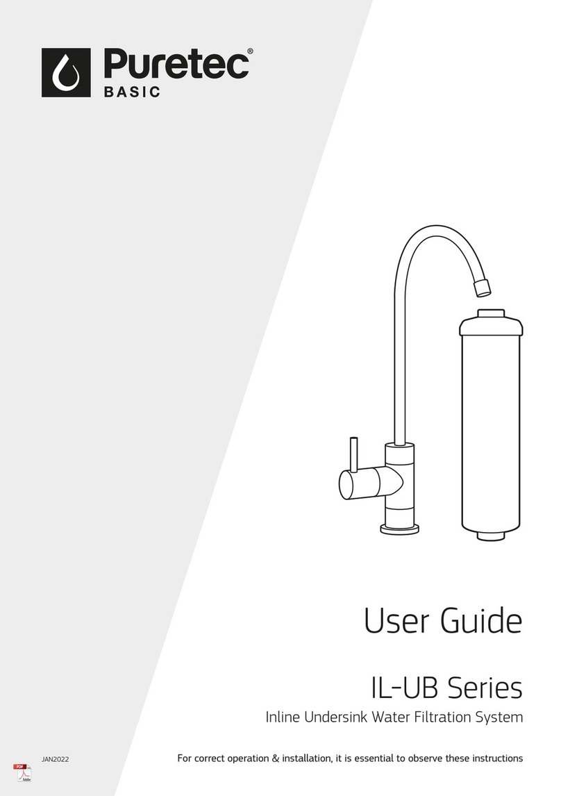
Puretec IL-UB Series User manual
Puretec
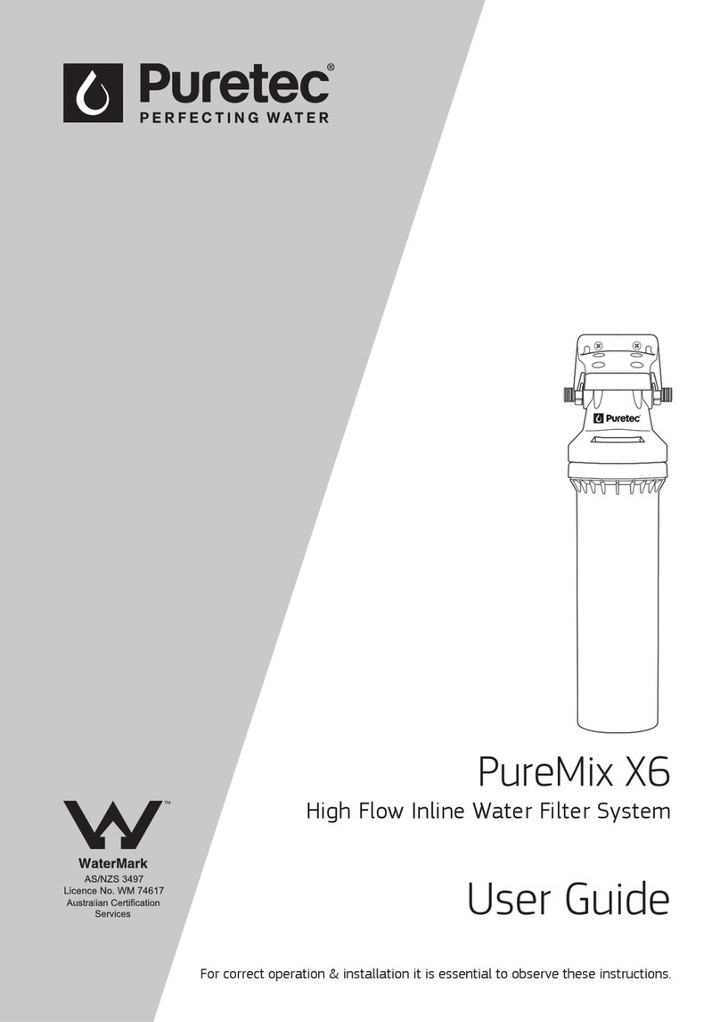
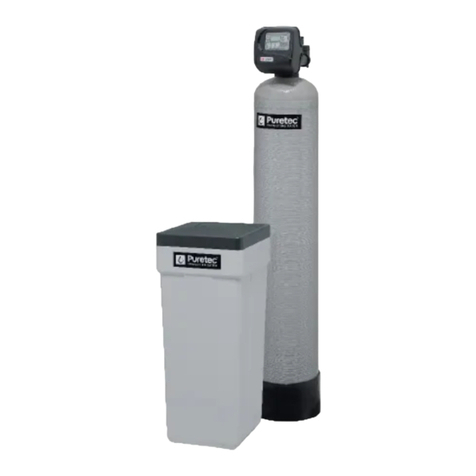
Puretec Puremix X6 User manual
Puretec
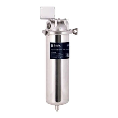
Puretec Multitrol MUL-E3 Series User manual
Puretec
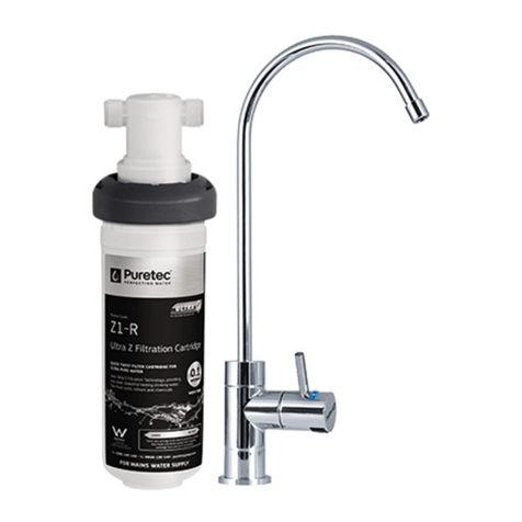
Puretec TSI Series User manual
Puretec
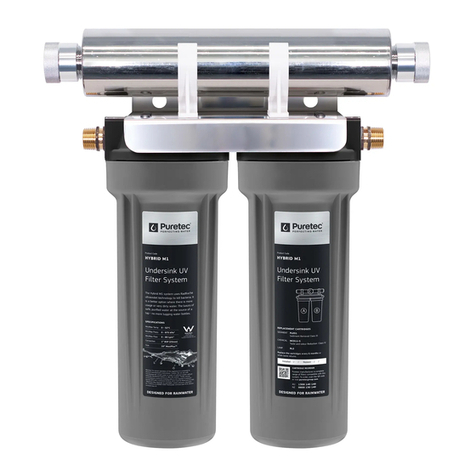
Puretec Z18 User manual
Puretec
Puretec Hybrid-M1 User manual
Puretec
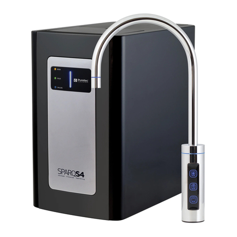
Puretec Sparq S4 User manual
Puretec
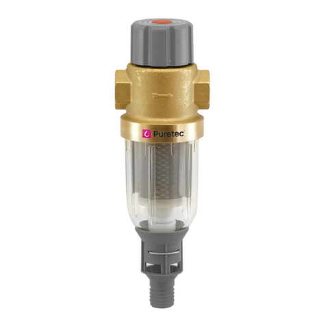
Puretec RI-HF19 User manual
Puretec
Puretec IMB Series User manual
Puretec
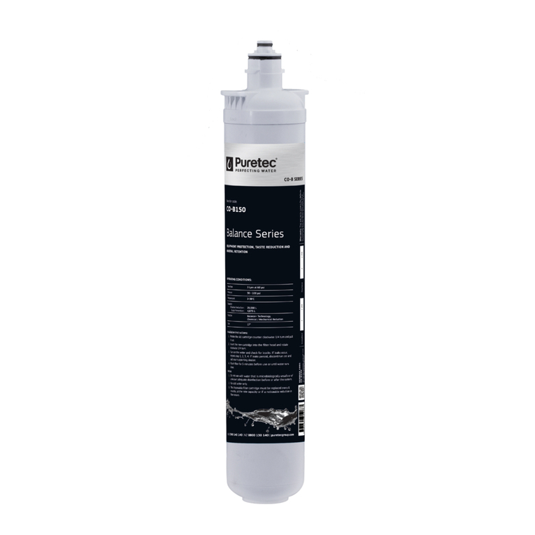
Puretec CO-I50 User manual
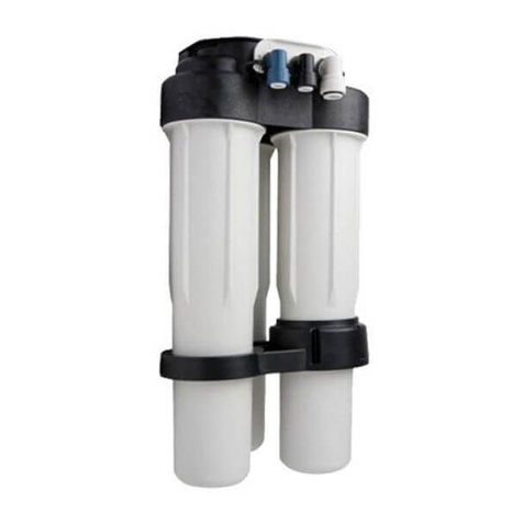
Puretec
Puretec ROS2700 User manual
Popular Water Filtration System manuals by other brands

Atlantic Ultraviolet
Atlantic Ultraviolet Mighty Pure MP16A owner's manual

SunSun
SunSun CBG-500 Operation manual

Hayward
Hayward XStream Filtration Series owner's manual

Contech
Contech DownSpout StormFilter Operation and maintenance

Teka
Teka Airfilter MINI operating instructions

Wisy
Wisy LineAir 100 Installation and operating instructions

Schaffner
Schaffner Ecosine FN3446 Series User and installation manual

Pentair
Pentair FLECK 4600 SXT Installer manual

H2O International
H2O International H20-500 product manual

Renkforce
Renkforce 2306241 operating instructions

Neo-Pure
Neo-Pure TL3-A502 manual

STA-RITE
STA-RITE VERTICAL GRID DE FILTERS S7D75 owner's manual
