Hornet Instruction Guide - Backrack
1Remove items from packaging. Check to see
if all parts from above table of contents are
included.
2
Use the 1/4”-20 nuts and bolts, 5/32” Allen, and the
7/16” wrench to attach the two clamps to the
bracket as shown in Figure 1. Tighten bolts
until bracket is held firmly in place.
Overtightening of the bolts could cause
warping of the bracket. Make sure to center
the bracket before fully tightening bolts.
3Attach the Hornet light to the now mounted
bracket using the 10-32 nylock nuts and bolts,
1/8” Allen, and 3/8” wrench. (Figure 2)
Figure 1: Bracket and clamp.
4Route the wire into and through the cab to a
suitable switch mounting location.
5To wire the switches properly, refer to the
wiring diagram in Figure 3.Figure 2: Mounted Hornet light.
NOTE: If you have purchased a 24” Hornet
light, at this point proceed to the other set of
instructions included. (24” Hornet Adapter
Installation: 950024I)
Putco guarantees its Stainless Steel and Aluminum products against defects in workmanship and material for
as long as you own your vehicle. All painted products have a 90 day warranty on the painted surface. Any defects
resulting from faulty material or workmanship will be warranted by Putco and repaired or replaced at our discretion.
Putco assumes no extra labor costs. Damages caused by freight carriers, improper installation, misuse, collision, or
neglect will not be warranted by Putco.
950007I
NOTE: When the switch is configured correctly it should
function as follows: The primary switch, or the switch
hooked up to the red wire, controls power to the Hornet
light. This switch will turn the light on and off. To switch
modes, the primary switch must be in the ON position.
While the Hornet light is receivng power via the red wire,
give 12V power to the yellow wire If it does not change
modes, check to make sure that the light is receiving power
from the primary switch. The light will remember the mode
even with the switch turned off.
Your new Hornet is now successfully
installed on your Backrack!
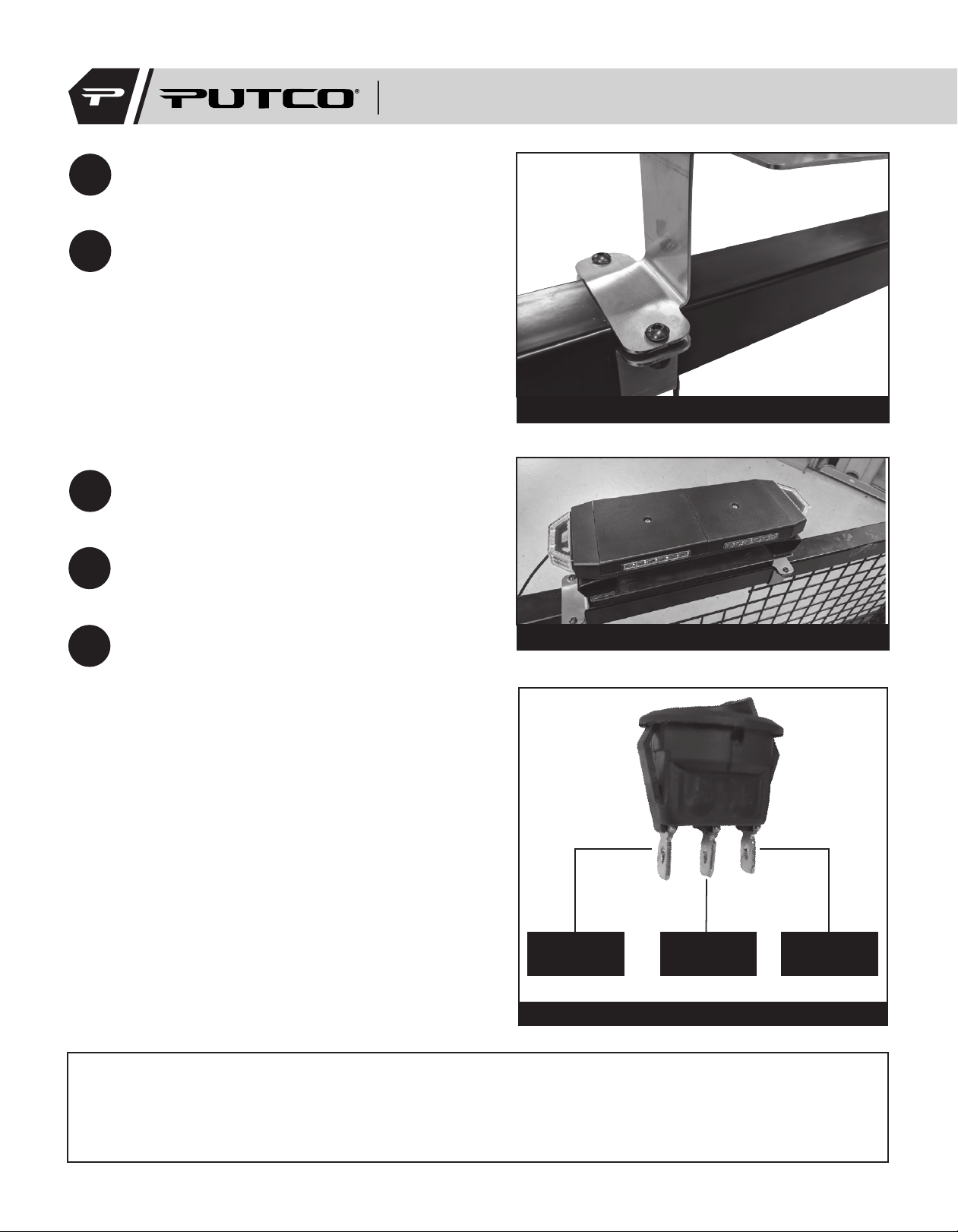
Figure 3: Switch wiring diagram.
Ground
(Gold post on switch)
+12V From
Batttery
Acc.
Red Wire
from Hornet


