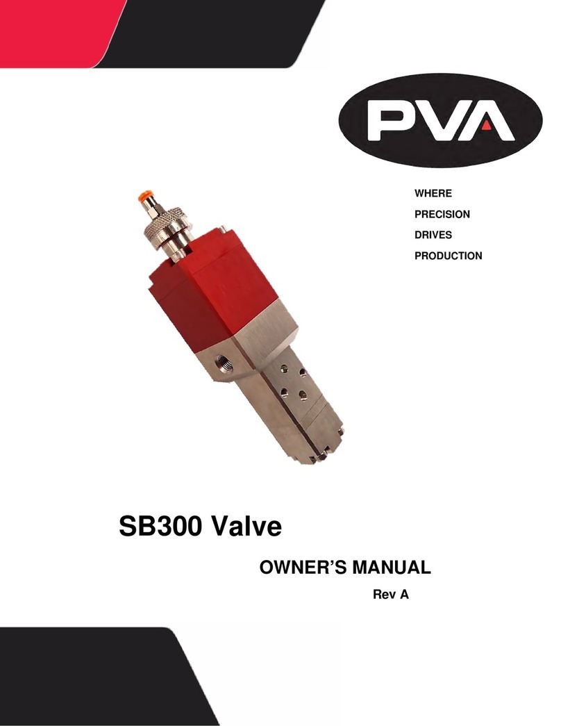
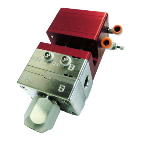
PVA CA300 User manual

This document is based on information available at the time of its publication. While efforts have been
made to be accurate, the information contained herein does not purport to cover all details or variations in
hardware or software, nor to provide for every possible contingency in connection with installation,
operation, or maintenance. Features may be described herein which are not present in all hardware and
software systems. Precision Valve & Automation, Inc. assumes no obligation of notice to holders of this
document with respect to changes subsequently made.
Precision Valve & Automation, Inc. makes no representation or warranty, expressed, implied, or statutory
with respect to, and assumes no responsibility for the accuracy, completeness, sufficiency, or usefulness of
the information contained herein. No warranties of merchantability or fitness for purpose shall apply.
This document, including the information contained herein, is the property of Precision Valve &
Automation, Inc. and is considered confidential and proprietary information. It is delivered on the express
condition that it not be used, disclosed, or reproduced in whole or in part, for any reason without prior
written consent of Precision Valve & Automation, Inc.
Copyright © 2015 Precision Valve & Automation, Inc.
All Rights Reserved.

Preface
CA300 Diaphragm Dispense Valve, Air Actuated
Thank you for purchasing the CA300 dispensing valve from PVA. Before attempting to
operate the CA300, we recommend that you take a few minutes and read the following
operation and setup manual. This will assist in familiarizing you with the product and
ensure a successful installation.
As always, if any questions or problems arise, do not hesitate to contact PVA’s Valve
Service Department for support. This department can be reached at PVA headquarters
via telephone or e-mail.
Again, thank you for your purchase, and we look forward to assisting you in the future as
you continue to improve your dispensing processes.
PVA Contact Information
Main Office
Technical Support
PVA
Six Corporate Drive
Halfmoon NY12065
Tel +1-518-371-2684
Fax +1-518-371-2688
Website http://www.pva.net
Email mailto: info@pva.net
Tel +1-518-371-2684
Email mailto: cs@pva.net

Table of Contents
Preface................................................................................................................................. 3
CA300 Diaphragm Dispense Valve, Air Actuated......................................................... 3
PVA Contact Information............................................................................................... 3
Safety .............................................................................................................................. 5
Setup ................................................................................................................................... 6
Tool Kit........................................................................................................................... 6
B12-2247 Includes:......................................................................................................... 6
Operation............................................................................................................................. 7
Routine Cleaning and Disassembly.................................................................................... 7
General Assembly Instructions........................................................................................... 8
Valve Assembly.............................................................................................................. 8
Spare Parts .......................................................................................................................... 9
CA3-SP Includes:............................................................................................................ 9
BILL OF MATERIALS FOR CA300 (B12-2097):...................................................... 10
Troubleshooting................................................................................................................ 11
Problem............................................................................................................................. 11
Possible Cause .................................................................................................................. 11
Corrective Action.............................................................................................................. 11
PVA Warranty Policy....................................................................................................... 12

Theory of Operation
The CA300 is an all plastic dispense valve that uses a unique rigid diaphragm design to
act as a front closing valve to accurately dispense small dots and fine beads. This valve
can be used in handheld applications, mounted on a fixture for hands free dispensing, or
mounted to a robot for automated dispensing. The all plastic construction allows
adhesives such as Cyanoacrylates and Anaerobics to be dispensed through the valve along
with a variety of other low to high viscosity fluids. Applications can include dispensing
dots, beads, or for potting.
The CA300 has a divorced design comprising of two major sections. These include:
•Air section (Aluminum top portion)
•Fluid section (Delrin body with Teflon diaphragm)
Air Section
The air section is an aluminum body with a simple piston/cylinder combination used to
open and close the valve. A stroke adjustment bolt in the upper air body controls how far
the piston and needle assembly can retract thus regulating the rate of fluid flow.
Fluid Section
The fluid section is made up of a Delrin with a rigid Teflon diaphragm connected to the
air piston. Fluid dispenses as the point of the diaphragm is lifted out of the fluid section
orifice then stops as it moves back into place. The stroke adjustment bolt of the air
cylinder regulates the distance that the diaphragm tip can lift out of the fluid section
orifice thus controlling rate of fluid flow.
Wetted Parts
Wetted parts on the CA300 include:
- Delrin
- Teflon
- Kalrez
- Polyethylene
Safety
Due to material contents being under pressure eye protection is required for
operators. Refer to MSDS sheets on material being dispensed for other precautions.

Setup
The CA300 requires a 2-position, 4-way air solenoid valve to actuate the air section. The
valve should be operated with clean, dry air between 60-100psi. Two #10-32 threaded air
ports are located on the air section of the valve. The port located on the side of the fluid
section is air to open the valve. The port located on the top of the stroke adjustment bolt is
air to close the valve. Quick connect air fittings are typically supplied with the CA300 to
fit 5/32” tubing. Note that the valve should be normally in the closed position.
Fluid is supplied to the CA300 through the 1/8”npt port located on the Delrin
fluid section of the valve.
Tool Kit
PVA offers standard tool kits for all dispensing valves. The tool kit for the CA300
is part number B12-2247, which includes all necessary tools to perform maintenance on
this dispense valve:
B12-2247 Includes:
Qty
Part Number
Description
1
0266244
8” Adjustable Wrench
1
26571
5/32” Hex Key
2
26563
3/32” Hex Key
1
9570K71
Hook and Pick Set
1
5415K61
Snap Ring Pliers
1
B62-2048
Silicone Lubricant for o-rings, 2.5cc
1
8511A17
Removable Thread Locker

Operation
Refer to assembly drawing 112-2869 for part reference numbers.
1) Plumb up the valve as outlined above in the Setup procedures.
2) Regulate the air pressure operating the valve between 60-100psi.
3) Making sure that the valve is not aimed toward anyone, cycle the valve several
times. When the valve is cycling, the piston can be heard hitting the stroke
adjustment bolt, and the rod (7) can be seen going up and down in the center.
If the valve is not cycling properly, refer to the Troubleshooting section
4) When the fluid delivery system is connected to the valve, pressurize the material
to be dispensed.
5) Once again cycle the valve open to purge. Fluid should begin to dispense from the
tip of the valve. Continue dispensing until all air is removed.
6) Check fluid connection for leaks. If the valve is leaking or dripping, refer to the
Troubleshooting section.
7) Adjust the material pressure until the desired fluid flow is achieved.
8) Turn the stroke adjustment bolt (12) until the desired flow rate is achieved.
Turning the adjustment clockwise will decrease the material flow rate and
counter-clockwise will increase the material flow rate. If the stroke is turned all
the way down, it will stop fluid flow entirely.
9) Once the stroke is set, tighten the set screw (20) against the stroke adjustment (12)
using a 0.050” Hex key.
Note: Refer to Troubleshooting section for any problems.
Routine Cleaning and Disassembly
Cleaning and rebuilding the valve will be required from time to time. A spare
parts kit, part # CA3-SP is available with all the normal wear parts included.
Fluid Section
1) If possible, flush the valve thoroughly with an appropriate solvent before
disassembly. (Refer to MSDS sheets of fluid for suggested solvent)
2) Begin disassembly by first removing fluid pressure from the system.
3) Remove operating air pressure from the valve.
4) Remove all pneumatic tubing and fluid delivery fittings, hoses, etc. from the
valve.
5) Using an adjustable wrench, unthread and remove the luer adapter (4) from the
fluid section (3).
6) Using a 3/32” Hex key, evenly remove the four machine screws (17) from the
bottom of the fluid section (3) that secure it to the separation block (1).
7) Slide the fluid section (3) away from the diaphragm (2) to remove the o-ring (21).
8) Unthread the diaphragm (2) from the rod (7) by turning it counter clockwise.
9) Clean all of the wetted parts thoroughly with an appropriate solvent.

10)Using a 3/32” Hex key, evenly remove the four machine screws (16) from the
upper air body (11) that secure it to the separation block (1). Note: During
removal that the spring (19) will force the air section apart.
Air Section
11)Separate the upper air body (11) assembly from the lower air body (5) assembly
to remove the spring (19) then slide the separation block (1) off the rod (7).
12)Using snap ring pliers, remove retaining ring (18) from the stroke adjust bolt (10).
13)Remove the 019 Buna o-ring (14) from the upper air body (11).
14)Using a 0.050” Hex Key, remove the set screw (20) from the upper air body (11)
15)Unthread and remove the stroke adjust bolt (10) from the upper air body (11) then
remove the 014 Buna o-ring (13) from the stroke adjust bolt.
16)Holding the lower air body (5) in one hand, grab the rod (7) to push the piston (6)
assembly out of the lower air body.
17)Remove the 007 Buna o-ring (10) from the bottom of the lower air body (5).
18)Hold the piston (6) with an adjustable wrench then use a 5/32” Hex key to
unthread and remove the set screw (8) to remove the rod (7) then remove the
116 Buna o-ring (9) from the piston.
Replace components with spares provided in the spare parts kit.
General Assembly Instructions
•All o-rings must be lubricated with a small amount of silicone grease.
•A small amount of removable thread locker should be applied to the set screw (8).
Valve Assembly
1) Mount the 014 Buna o-ring (13) onto groove of the stroke adjust bolt (12).
2) Thread the stroke adjust bolt (12) into the upper air body (11) then insert the set
screw (20) using a 0.050” Hex key but leave loose.
3) Using snap ring pliers, mount the retaining ring (18) onto the stroke adjust bolt
(12) then turn the stroke adjust bolt counter clockwise until the end of its travel.
4) Mount the 019 Buna o-ring (14) onto the upper air body (11).
5) Drop the rod (7) into the piston (6) and assemble with the set screw (8) using an
adjustable wrench and 5/32” Hex key to tighten.
6) Mount the 116 Buna o-ring (9) onto the piston (6).
7) Apply a small amount of silicone grease to the inside of the lower air body (5)
then drop in the piston and rod assembly.
8) Mount the 007 Buna o-ring onto the end of the rod (7) and slide it down into the
groove of the lower air body (5).
9) Insert the threaded of the rod (7) through the smaller ID hold of the separation
block (1) until the separation block hits the lower air body (5).

10)Place the spring (19) onto the lower air body (5) on top of the piston (6) then
place the upper air body (11) onto the spring and assemble using four machine
screws (16) using a 3/32” Hex key to tighten them down evenly.
11)Thread the diaphragm (2) onto the end of the rod (7) until it is secure the continue
turning until it is square with the body of the valve.
12)Place the o-ring (21) into the groove of the fluid section (3).
13)Place the fluid section (3) onto the diaphragm and assemble using the four
machine screws (17) using a 3/32” Hex key to tighten them down evenly.
14)Thread the plastic luer adapter (4) into the bottom of the fluid section (3) and
tighten using an adjustable wrench.
Note: Be sure not to over tighten the luer adapter.
Spare Parts
PVA offers standard spare parts kits for all dispensing valves. These kits are
stocked for immediate shipment and allow replacement of all wearable parts of the valve.
The spare parts kit for this valve, product number CA3-SP, includes the following
components:
CA3-SP Includes:
Qty
Part Number
Description
1
114-9539
Diaphragm
1
V300-UV
Luer Adapter
1
VLV-116B
Buna O-Ring
1
VLV-007B
Buna O-Ring
1
VLV-014B
Buna O-Ring
1
VLV-019B
Buna O-Ring
1
VLV-016K
Kalrez O-Ring

1.700
0.750
1.150
1.150
3.780
0.5
A
1 OF 2N/A
REV:SHEET:PART FINISH: 112-2869
SEE BOM TABLE
DRAWING NUMBER:MATERIAL:
CA300
PART TITLE:
Precision Valve & Automation
One Mustang Drive
Cohoes, NY 12047
This document, including the
information contained herein,
is the property of PRECISION
VALVE & AUTOMATION, Inc. and
is considered confidential
and proprietary information.
It is delivered on the express
condition that it not be used,
disclosed, or reproduced in
whole or in part, for any
reason without prior written
consent of PRECISION VALVE &
AUTOMATION, Inc.
DESIGNDATEDRN BYREVISION DESCRIPTIONREV
RJB19FEB09RJBREF. BOM # B12-2097A
JA4/9/15DERADD O-RINGB
C
D
E
F
UNLESS OTHERWISE SPECIFIED
DIMENSIONS ARE IN INCHES
DECIMAL ANGULAR
.X # 0.2 # 0.5$
.XX # 0.01
.XXX # 0.005
.XXXX # 0.0005
(2X)
0.189 CLR THRU
0.324 0.050
(C'BORE FOR M4x.7)
AIR PORT, #10-32 THREAD
(AIR TO OPEN)
1/8" NPT FLUID INLET
AIR PORT, #10-32 THREAD
(AIR TO CLOSE)

A
A
A
2 OF 2N/A
REV:SHEET:PART FINISH: 112-2869
SEE BOM TABLE
DRAWING NUMBER:MATERIAL:
CA300
PART TITLE:
Precision Valve & Automation
One Mustang Drive
Cohoes, NY 12047
This document, including the
information contained herein,
is the property of PRECISION
VALVE & AUTOMATION, Inc. and
is considered confidential
and proprietary information.
It is delivered on the express
condition that it not be used,
disclosed, or reproduced in
whole or in part, for any
reason without prior written
consent of PRECISION VALVE &
AUTOMATION, Inc.
DESIGNDATEDRN BYREVISION DESCRIPTIONREV
RJB19FEB09RJBREF. BOM # B12-2097A
JA4/9/15DERADD O-RINGB
C
D
E
F
UNLESS OTHERWISE SPECIFIED
DIMENSIONS ARE IN INCHES
DECIMAL ANGULAR
.X # 0.2 # 0.5$
.XX # 0.01
.XXX # 0.005
.XXXX # 0.0005
REF # PART NUMBER REV DESCRIPTION QTY MATERIAL S/P KIT
1 114-8514 E SEPARATION BLOCK 1 300 SERIES SST
2 114-9539 B DIAPHRAGM 1 BLACK TEFLON *
3 114-8546 F FLUID BODY 1 BLACK DELRIN
4 V300-UV LUER ADAPTER, MALE 1 BLACK DELRIN *
5 114-8515 C LOWER AIR BODY 1 ALUMINUM
6 V224 C PISTON 1 303 STAINLESS STEEL
7 114-8523 B ROD 1 303 SS
8 V079 SET SCREW 1 18-8 STAINLESS STEEL
9 VLV-116B O-RING, -116, BUNA-N 1 BUNA-N *
10 VLV-007B O-RING, -007, BUNA-N 1 BUNA-N *
11 114-8917 C UPPER AIR BODY 1 ALUMINUM
12 114-8916 B STROKE ADJUST 1 300 SERIES
13 VLV-014B O-RING, -014, BUNA-N 1 BUNA-N *
14 VLV-019B O-RING, -019, BUNA-N 1 BUNA-N *
15 95110A112 EXPANSION INSERT 1 18-8 SS *
16 SH5-40-1500 CAP SCREW, #5-40 4 STEEL
17 SH5-40-1250 CAP SCREW, #5-40 4 STEEL
18 98410A117 SNAP RING, 0.338" ID 1
19 01511 SPRING 1 SPRING STEEL *
20 90291A106 SETSCREW, #4-40 X .25" 1
21 VLV-016K O-RING, -016, KALREZ 1 KALREZ *
20
SECTION A-A
1
2
3
4
5
6
7
8
9
10
11
12
13 14
15
18
19
21

BILL OF MATERIALS FOR CA300 (B12-2097):
Refer to Drawing #: 112-2869
Item
Part Number
Description
Quantity
1
114-8514
Separation Block
1
2
114-9539
Diaphragm
1
3
114-8546
Fluid Section, Delrin
1
4
V300-UV
Luer Adapter
1
5
114-8515
Lower Air Body
1
6
V224
Piston
1
7
114-8523
Rod
1
8
V079
Set Screw
1
9
VLV-116B
Buna O-Ring
1
10
VLV-007B
Buna O-Ring
1
11
114-8917
Upper Air Body
1
12
114-8916
Stroke Adjust
1
13
VLV-014B
Buna O-Ring
1
14
VLV-019B
Buna O-Ring
1
15
95110A112
Insert, Threaded
1
16
SH5-40x1.50
Socket Head Cap Screw
4
17
SH5-40c1.25
Socket Head Cap Screw
4
18
98410A117
Retaining Ring
1
19
01511
Spring
1
20
90291A106
Setscrew, #4-40 x 0.25” w/ nylon tip
1
21
VLV-016K
Kalrez O-Ring

Troubleshooting
Problem
Possible Cause
Corrective Action
Valve does not cycle
Air pressure to air section is too low
Stroke adjustment bolt is bottomed out
Material has cured in the valve
Valve was assembled w/o lubricating the O-
ring seals
Increase air pressure to between 60-100 psi
Back out stroke adjustment bolt by turning it
counter-clockwise
Disassemble and clean valve
Disassemble valve, lubricate seals and re-
assemble
Material leaks from
valve tip
Diaphragm is worn
Air bubble trapped in fluid body or in
dispense needle
Replace diaphragm
Flip valve upside down and cycle until air bubbles
are removed
Valve leaks from
mid-section
Diaphragm is worn or damaged
Replace diaphragm
Valve does not
dispense anything
Fluid pressure is too low
Material has cured in fluid section
Stroke adjustment bolt is set too low
Increase fluid pressure
Disassemble and clean valve
Back out stroke adjustment bolt by turning it
counter-clockwise
Air bubbles in fluid
Valve not properly purged
Problem with fluid delivery system
Flip valve upside down and cycle until air bubbles
are removed
Diagnose and repair.
Dispense rate too fast
Fluid pressure set too high
Stroke adjust set too high
Dispense tip gauge too large
Decrease fluid pressure
Turn stroke adjust clockwise
Replace dispense tip with smaller size
Dispense rate too
slow
Fluid pressure set too low
Stroke adjust set too low
Dispense tip gauge too small
Increase fluid pressure
Turn stroke adjust counter-clockwise
Replace dispense tip with larger size

PVA Warranty Policy
PVA warrants the enclosed product against defects in material or workmanship on all components
for one year from the date of shipment.
The warranty does not extend to components damaged due to misuse, negligence, or installation
and operation that is not in accordance with the recommended factory instructions. Unauthorized repair or
modification of the enclosed product, and/or the use of spare parts not directly obtained from PVA (or from
factory authorized dealers) will void all warranties.
All PVA warranties extend only to the original purchaser. Third party warranty claims will not be
honored at any time.
Prior to returning a product for a warranty claim, a return authorization must be obtained from
PVA’s customer service department. Authorization will be issued either via the telephone, facsimile, or in
writing upon your request.
To qualify as a valid warranty claim, the defective product must be returned to the factory during
the warranty period. Upon return, PVA will repair (or replace) all components found to be defective in
material or workmanship.
(Retain this for your records)
Product Information:
PRODUCT: ________________________________________
SERIAL NUMBER: _________________________________
DATE OF PURCHASE: ______________________________
Table of contents
Other PVA Control Unit manuals
Popular Control Unit manuals by other brands

Phytec
Phytec phyCORE-MPC5200B tiny Hardware manual

Danfoss
Danfoss 103E5 Installation & user's instructions

Siemens
Siemens V-2030 instruction manual

Emerson
Emerson Fisher EZ-C instruction manual

Texas Instruments
Texas Instruments BoosterPack BOOSTXL-ADS7142-Q1 user guide

Bosch
Bosch ISP-EMIL-120 installation manual