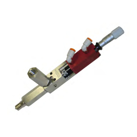
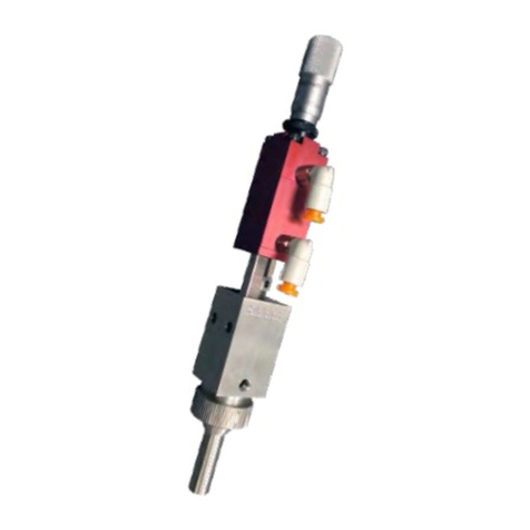
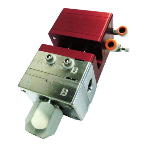
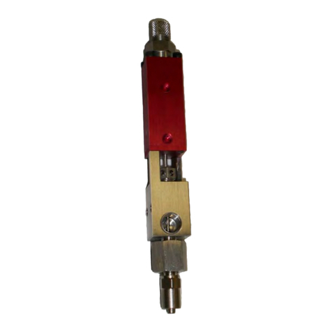
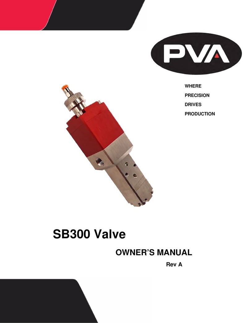
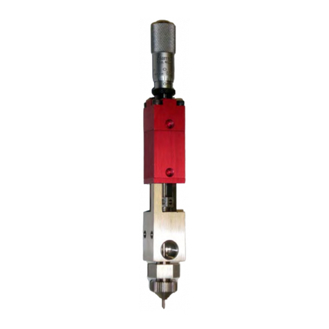
PVA JDX User manual

Precision Valve & Automation
One Mustang Drive
Cohoes, NY 12047
www.pva.net
JDX Jet Valve
OWNER’S MANUAL
Revision H
WHERE
PRECISION
DRIVES
PRODUCTION

JDX
PVA
Revision H (2016)
2 of 39
This document is based on information available at the time of its publication. While
efforts have been made to ensure the contents of this manual are accurate, the
information contained herein does not purport to cover all specific details or variations
in hardware, or to provide for every possible contingency in connection with
installation, operation, or maintenance. Features may be described herein which are not
present in all hardware and software systems. Precision Valve and Automation, Inc.
assumes no obligation of notice to holders of this document with respect to changes
subsequently made.
Precision Valve and Automation, Inc. makes no representation or warranty, expressed,
implied, or statutory with respect to, and assumes no responsibility for the accuracy,
completeness, sufficiency, or usefulness of the information contained herein. No
warranties of merchantability or fitness for purpose shall apply.
This document, including the information contained herein, is the property of
Precision Valve and Automation, Inc. and is considered confidential and
proprietary information. It is delivered on the express condition that it not be
used, disclosed, or reproduced, in whole or in part, for any reason without prior
written consent of Precision Valve and Automation, Inc.
Copyright © 2016
Precision Valve and Automation, Inc.
All Rights Reserved.

JDX
PVA
Revision H (2016)
3 of 39
Table of Contents
Introduction ............................................................................................. 51.
Document History ............................................................................................... 51.2
Safety .................................................................................................................. 61.3
Theory of Operation............................................................................................71.4
Description of Components ................................................................................ 71.5
Personal Protective Equipment ..........................................................................71.6
Waste Disposal.................................................................................................... 71.7
Necessary Tools ..................................................................................................81.8
Setup........................................................................................................ 82.
Overview .............................................................................................................82.1
Operation................................................................................................. 93.
Install the Diaphragm.......................................................................................... 93.1
Install Nozzle Plate and Feed Tube ...................................................................103.2
Prime the Jet .....................................................................................................123.3
Set the Heater Temperature.............................................................................133.4
Set Fluid Pressure ..............................................................................................133.5
Jet Pressure .......................................................................................................143.6
Jet Shutdown Procedure ...................................................................................143.7
Clean the Wetted Parts.....................................................................................163.8
Replace the Orifice............................................................................................173.9
Maintenance .......................................................................................... 214.
Flush the System ...............................................................................................214.1
How to Use the Valve with Portal ........................................................... 225.
Setup Mode....................................................................................................... 225.1
Select a Recipe ..................................................................................................245.2
Jetter Maintenance...........................................................................................255.3
How to Use the Jet with the PVA JDX Jet Valve Controller ....................... 266.
Jet and Fluid Pressure .......................................................................................286.1
Temperature Controller....................................................................................286.2
To change the SV temperature .................................................................286.2.1

JDX
PVA
Revision H (2016)
4 of 39
To turn ON the heater............................................................................... 296.2.2
To turn OFF the heater..............................................................................296.2.3
LCD Display Functions and Selection Keys ........................................................306.3
Trigger Button and LED ..................................................................................... 316.4
Exploded View........................................................................................ 327.
Item Numbers and Descriptions ............................................................... 327.1.1
Replacement Parts and Accessories ........................................................ 338.
Technical Specifications.......................................................................... 359.
Troubleshooting ..................................................................................... 3610.
Notes ..................................................................................................... 3711.
Warranty................................................................................................ 3812.
Table of Figures ...................................................................................... 3913.

JDX
PVA
Revision H (2016)
5 of 39
Introduction1.
Before you operate this system, read the operation and setup manual. This will help you
to become familiar with the product and ensure successful operation.
If any questions or problems arise, contact PVA’s Technical Support department for
support.
PVA Contact Information1.1
Main Office PVA
One Mustang Drive
Cohoes, NY 12047
Tel +1-518-371-2684
Fax +1-518-371-2688
Website http://www.pva.net
Email mailto: info@pva.net
Technical Support
Tel +1-518-371-2684
Document History1.2
Revision
Revision Date
Reason for Changes
Rev H
March 2016
Updated Part Numbers
Rev G
July 2015
Updated Part Numbers
Rev F
May 2015
Updated O-ring Information
Rev E
Dec. 2014
Updated Controller Content
Rev D
Fall 2014
Updated to Include HV-2000 Controller
Rev C
Oct. 2014
Updated Nozzle Content
Rev B
May 2014
Updated to Include Portal Screens
NOTE: All photographs and CAD model representations in this document are a
“general representation” of the valve and its components. The actual
appearance of the valve and its components can differ based upon customer
specific configuration.

JDX
PVA
Revision H (2016)
6 of 39
Safety1.3
Certain warning symbols are affixed to the machine and correspond to notations in this
manual. Before operating the system, identify these warning labels and read the notices
described below. Not all labels may be used on any specific system.
Always wear approved safety glasses when you operate or
work near the workcell.
Before you operate the system, read and understand the
manuals provided with the unit.
Never put hands or tools in areas with this symbol when the
machine is in operation. A dangerous condition may exist.
Read and understand the manuals provided with the unit
before any repairs or maintenance is done. Only a qualified
individual should do service.
Use caution when there are pressurized vessels. Find and
repair any leaks immediately. Always wear appropriate safety
equipment when you work with pressurized vessels or vessels
that contain chemicals.
Shear hazard from moving parts. Avoid contact.

JDX
PVA
Revision H (2016)
7 of 39
Theory of Operation1.4
The JDX Jet Valve is a high speed, non-contact dispenser that applies small shots of fluid
as individual dots or in rapid succession. Only 3 components come in contact with fluid:
the feed tube, diaphragm, and nozzle plate. The unique diaphragm design allows for fast
cycling of the jet, up to 300Hz for high speed line dispensing. The JDX is designed to
dispense coatings, underfill, encapsulant, SMT glue, grease, and more with very fine
control.
Description of Components1.5
Refer to Section 2.1 for an overview image.
Component
Description
Syringe Bracket
The bracket for 30cc syringe is one piece with jet body. Inserts are
available for smaller syringe sizes.
Jet Body
This component contains the pneumatic solenoid that controls the
on/off function of the jet.
Heater
Built into jet body, the fluid is warmed at the point of dispense.
Feed Tube
A disposable tube with a female luer fitting. It supplies fluid from the
syringe to the nozzle plate.
Diaphragm
Small component that fits into the heater and is held in position by the
nozzle plate. It comes in three materials for dispense material
compatibility.
Nozzle Plate
The nozzle plate has the dispense port orifice in it and is connected to
the syringe with the feed tube. The nozzle plate is available in multiple
sizes and materials of dispense ports orifices.
Personal Protective Equipment1.6
Operators must use eye protection because material contents are under pressure.
Always wear gloves when handling materials and solvents. Refer to MSDS sheets on the
material being dispensed for other precautions.
Waste Disposal1.7
Dispose of all used parts and materials in accordance with local laws and regulations.

JDX
PVA
Revision H (2016)
8 of 39
Necessary Tools1.8
PVA offers tools and cleaning accessories to maintain the JDX jet valve.
Part Number
Description
02597
3mm hex wrench
Philips screwdriver
Setup2.
Before you operate the jet, know the components. Follow the steps instructed below for
safe and correct operation.
Overview2.1
Figure 1: Jet Components

JDX
PVA
Revision H (2016)
9 of 39
Operation3.
NOTE: Use only compatible solvents and materials or the seals and O-rings will
be damaged.
The sections that follow are in the recommended order to operate the jet valve. Do the
sub-sections in Section 3, in the order shown.
NOTE: The jet valve is shown removed from the workcell in the procedures
below. It is not necessary to remove the jet valve to do the procedures.
Install the Diaphragm3.1
1. Set the jet valve to open with the operator interface of JDX controller box.
2. Align the ribs on top of the diaphragm to the groove features on the bottom of
the heater block.
Figure 2: Diaphragm and Heater Block Grooves
3. Put the diaphragm on your finger tip and gently press it into heater block with
metal insert aligned with the center hole.
Figure 3: Diaphragm Installed in the Heater Block
Grooves on the
heater block

JDX
PVA
Revision H (2016)
10 of 39
Install Nozzle Plate and Feed Tube3.2
1. Align the feed tube with the barb inlet on the nozzle plate.
2. Push the feed tube onto the barb inlet.
Figure 4: Feed Tube and Nozzle Plate
3. Align the nozzle plate on the heater block with the barb inlet facing toward the
syringe bracket. The heater block has two locating pins that will guide the
nozzle plate onto the heater block.
Figure 5: Align the Heater Block and Nozzle Plate
4. Make sure the nozzle plate faces the correct way.
Figure 6: Nozzle Plate

JDX
PVA
Revision H (2016)
11 of 39
5. Use a hex wrench to tighten the recessed screws in the two holes shown. Turn
the screws clockwise until they are tight and the nozzle plate does not move.
Figure 7: Tighten the Screws to Attach the Nozzle Plate
6. Install the syringe into holder.
7. Push the feed tube into the end of the syringe.
Figure 8: Install the Fluid Syringe
8. Turn the thumb screw clockwise until the fluid syringe is tight in holder.

JDX
PVA
Revision H (2016)
12 of 39
Prime the Jet3.3
1. Set the jet to close with the operator interface or JDX controller box.
2. Fill the syringe with material.
3. Attach the air cap to the syringe.
Figure 9: Attach the Air Cap
4. Set the supply pressure to 10 psi.
5. Check the jet and syringe for fluid leaks.

JDX
PVA
Revision H (2016)
13 of 39
Set the Heater Temperature3.4
The temperature can be adjusted to improve dispense quality. The fluid will dispense
with a cleaner break and better flow when the heat is set correctly. The viscosity and
rheology of the material have an effect on the necessary dispense temperature.
Generally the higher the viscosity the more heat you will need.
1. Turn on heater and wait 5-10 minutes for the temperature to stabilize.
2. Examine the table shown below to find a good temperature to start with.
Table 1: Fluid Viscosity And Dispense Temperatures
Fluid Type
Viscosity cps
Temperature °C
Hysol 3800
300
35
EMI3553
1K
40
EMI 1748S-HTG-HV3
400K
45
Loctite 3621
50K
45
EMI 1768-VTG
65K
45
Alpha WS-619
100K
50
Norland 123 TKHGA
200K
50
Namics 8439
50K
55
Namics 8410
60K
55
3. Use trial and error to find the best temperature setting for your material. Fluid
viscosity does not directly relate to the necessary temperature.
WARNING: If the temperature is set too high the material will cure in the
nozzle plate.
Set Fluid Pressure3.5
The fluid pressure supplies the material to the jet chamber to keep the drop size correct
and consistent. Higher fluid pressure is usually better.
1. Set the jet to open with the operator interface or JDX controller box.
2. Start at 10 psi and increase the fluid pressure until a steady stream or a
continuous flow of dots exit the nozzle. Fluids react differently, some may curl
up or pool at the nozzle outlet.
Refer to Section 10 for more information.

JDX
PVA
Revision H (2016)
14 of 39
Jet Pressure3.6
Jet pressure is the force that pushes the fluid out of the jet when it is dispensed. Too
little jet pressure and the fluid will not leave the nozzle completely and material will
accumulate on the nozzle. Too much jet pressure and the fluid will have satellites or
splatter when it hits the surface of the product. Jet pressure must be between 35-65 psi
to work correctly.
1. Set jet pressure at 45 psi to start.
2. Dispense the material and examine the nozzle and surface that was dispensed
on for buildup, splatter, or satellites.
3. Adjust the jet pressure until the results are correct.
Do not set jet pressure higher than 65 psi.
Jet Shutdown Procedure3.7
1. Decrease system pressure to 0 psi.
2. Shut off the heater and wait approximately five minutes for the heater block to
cool.
3. Turn the air cap counterclockwise to remove it.
4. Turn the thumb screw counterclockwise to loosen the syringe.
Figure 10: Remove the Air Cap and Loosen the Thumb Screw
Turn Counterclockwise
to Loosen
Turn Counterclockwise
to Loosen

JDX
PVA
Revision H (2016)
15 of 39
5. Loosen and remove the feed tube off of the syringe.
6. Remove the syringe.
Figure 11: Remove the Syringe
7. Use a 3mm hex wrench to loosen the two recessed screws and remove the
nozzle plate.
Figure 12: Remove the Nozzle Plate
8. Remove the diaphragm.

JDX
PVA
Revision H (2016)
16 of 39
Clean the Wetted Parts3.8
1. Clean the diaphragm with cotton tipped swabs and solvent.
Figure 13: Clean the Diaphragm
2. Remove the feed tube from the nozzle plate and discard it.
3. If necessary, soak the nozzle plate in ultrasonic cleaner for 5 minutes.
4. Clean the nozzle plate with cotton tipped swabs and solvent.
Figure 14: Clean the Nozzle Plate
5. Examine the parts for wear, replace if necessary.

JDX
PVA
Revision H (2016)
17 of 39
Replace the Orifice3.9
1. Loosen the three screws in the nozzle plate.
Figure 15: Remove the Nozzle Plate Screws
2. Remove the barb plate.
Figure 16: Remove the Barb Plate
3. Remove the O-ring from the barb plate. Clean and replace as necessary.
Figure 17: Remove the O-ring
NOTE: There is an O-ring on the barb plate and one on the orifice. Make sure
you keep them separate; the O-ring on the barb plate is slightly larger than the
orifice O-ring and they are not interchangeable.

JDX
PVA
Revision H (2016)
18 of 39
Figure 18: Barb Plate and Orifice O-rings
4. Remove the orifice (the orifice shown is ceramic; you may have a different
orifice). You may have to turn the nozzle plate over and push on the orifice tip
to remove the orifice.
Figure 19: Remove the Orifice
5. Clean the nozzle plate, barb plate, and O-ring if necessary.
6. Install a new orifice. Make sure the orifice has an O-ring installed.
Figure 20: Install the Orifice
7. Install the barb plate. Make sure the nozzle plate screw holes are aligned.

JDX
PVA
Revision H (2016)
19 of 39
Figure 21: Install the Barb Plate
8. Turn the nozzle plate over and install the three screws. Make sure the screws
are correctly tightened. Do not damage the screws when you tighten them
Figure 22: Install the Nozzle Plate Screws
9. Install the barb plate O-ring.
Figure 23: Install the O-ring
The above example is a ceramic orifice; you may have an extended nozzle or a carbide
orifice, as shown below.

JDX
PVA
Revision H (2016)
20 of 39
Figure 24: Extended Nozzle and Carbide Orifice Examples
NOTE: Nozzle plates have the part number and orifice size engraved in them.
Figure 25: Nozzle Plate Part Number
Table of contents
Other PVA Control Unit manuals
Popular Control Unit manuals by other brands

Moxa Technologies
Moxa Technologies CA-134I Quick installation guide

A.R.I.
A.R.I. D-025 L ARISENSE Installation operation & maintenance

KLINGER SCHÖNEBERG
KLINGER SCHÖNEBERG RK-Proball KH 1T M Assembly and Repair Instructions

Truma
Truma iNet Box installation instructions

Terasic
Terasic SDI-FMC user manual

Sterling
Sterling Royal Series Operation and installation manual

Chord Electronics
Chord Electronics Poly user manual

Automationdirect.com
Automationdirect.com Productivity 2000 P2-08TD1S manual

Graco
Graco 244912 Instructions-parts list

Viega
Viega Grundfix Plus-Control manual

Spectrum Digital
Spectrum Digital TMS320VC5509 Technical reference

BETAFPV
BETAFPV Micro TX user manual