PVA PC100 User manual

PC100
Plural Component Dispense Valve
Thank you for purchasing the PC100 dispensing valve from PVA. Before
attempting to operate the PC100, we recommend that you take a few minutes and read the
following operation and setup manual. This will assist in familiarizing you with the
product and ensure a successful installation.
As always, if any questions or problems arise, do not hesitate to contact PVA’s
Valve Service Department for support. This department can be reached at PVA
headquarters via telephone or e-mail.
Again, thank you for your purchase, and we look forward to assisting you in the
future as you continue to improve your dispensing processes.
Theory of Operation
The PC100 is a high pressure, front closing stainless steel plural component
dispensing valve that can be used to dispense two-part fluids. Applications include
potting, bead placement, and gaskets where a low flow rate is required. This valve works
most favorably with lower viscosity unfilled fluids. Part A and part B fluids will flow into
the valve separately and out of the valve separately into a disposable static mixer. No
disassembly and cleaning of the valve is required at the end of the day.
The PC100 has a divorced design comprising of two major sections. These include:
1) Two air sections (red anodized portions)
2) Fluid section (stainless steel portion)
The separate air sections are aluminum bodies with a simple piston/cylinder
combination used to open and close the valve. Stroke adjustment bolts in the upper air
bodies controls how far the piston and needle assembly can retract.
The fluid section is a stainless steel body, which includes a needle and seat
combination on each side of the valve to control fluid flow of part A and part B. Fluid
dispenses as the needles retracts out of the seats, then stops as the needles moves back
into the seats. The stroke adjustment bolts regulate the distance that the needles can
retract out of the seats thus controlling the rate of fluid flow. Fluids can include but are
not limited to any lower viscosity unfilled epoxies, urethanes, silicones, etc.
Wetted parts on the PC100 include:
- 303, 304 stainless steel
- Teflon
- Kalrez

Safety
Due to material contents being under pressure eye protection is required for
operators. Refer to MSDS sheets on material being dispensed for other precautions.
Setup
The PC100 requires a 2-position, 4-way air solenoid valve to actuate the air
section. The valve should be operated with clean, dry air between 60-100psi. Four #10-32
threaded air ports are located on the air sections of the valve. The ports located furthest
from the midsection of the valve are air to close the valve. The ports located closest to the
mid-section of the valve are air to open the valve. Air supplies used to open and close the
valve should be tied to the same solenoid to maintain uniform control. Quick connect air
fittings are typically supplied with the PC100 to fit 5/32” tubing. Note that the valve
should be normally in the closed position.
Fluid is supplied to the PC100 through the 1/8”npt ports located on the stainless
steel fluid section of the valve. Part A fluid should be connected to the port on the left
and Part B fluid should be connected to the port on the right.

Tool Kit
PVA offers standard tool kits for all dispensing valves. The tool kit for the PC100
is part number B12-1829, which includes all necessary tools and lubricating grease to
perform maintenance on this dispense valve:
B12-1829 Includes:
Qty
Part Number
Description
2
0266244
8” Adjustable Wrench
2
26563
3/32” Allen Key
1
26561
5/64” Allen Key
1
5516A18
Tweezers
1
B62-0752
2.5cc Mineral Oil Lubrication Kit
1
B62-2048
2.5cc Silicone Lubricant
1
9570K71
Hook and Pick Set
1
0266255
Pliers
2
53085A61
Soft Plastic Covers for Pliers
1
MM115
Removable Thread Locker
Operation
Refer to assembly drawing 112-1352 for part reference numbers.
1) Plumb up the valve as outlined above in the Setup procedures.
2) Regulate the air pressure operating the valve between 60-100psi.
3) Making sure that the valve is not aimed toward anyone, cycle the valve several
times. When the valve is cycling, both pistons can be heard hitting the stroke
adjustment bolts, and the needles (3) can be seen going up and down in the center
simultaneously.
Note: If the valve is not cycling properly, refer to the Troubleshooting section.
4) When the fluid delivery system is connected to the valve, pressurize the fluids to
be dispensed.
5) Once again, cycle the valve open to purge. Part A and B should begin to flow
separately out of the fluid manifold (1), continue dispensing until air is removed.
6) Check fluid connection and packing nuts (6) for leaks. If the valve is leaking,
refer to the Troubleshooting section.
7) Turn the stroke adjustment bolts (19) until the desired flow rate is achieved from
each fluid. Turning the adjustments clockwise will decrease the material flow rate
and counter-clockwise will increase the material flow rates. If the stroke
adjustment bolts are turned all the way down it will stop the flow of fluid entirely.
8) Once the stroke adjustment settings are determined, use the adjustable wrench to
tighten the lock nuts (20) up against the upper air bodies (11).
9) Attach a static mixer to the manifold (1) and use the retaining nut (23) to lock it in
place tightening with an adjustable wrench
Note: Refer to Troubleshooting section for any problems.

Periodic Maintenance
1) Lubricate the packing’s (5) on the PC100 valve every 200 hrs by placing a few
drops of mineral oil or other light oil inside the packing nut.
*Note: PVA offers a 2.5cc mineral oil lubrication kit; Part#: B62-0752
2) The packing nuts (6) will require occasional tightening, as wear occurs in order to
prevent leaks through the packing.
3) At the end of each day, remove and dispose of the static mixer, then replace the
mixer with a night cap to prevent material exposure to the atmosphere.
*Note: PVA offers a standard night cap seal; Part#: 165-CAP
Routine Cleaning and Disassembly
Cleaning and rebuilding the valve will be required from time to time. A spare
parts kit, part # PC1-SP is available with all the normal wear parts included.
1) Begin disassembly by removing air and fluid pressure from the valve.
2) Remove all pneumatic tubing and fluid delivery fittings, hoses, etc. from the
valve.
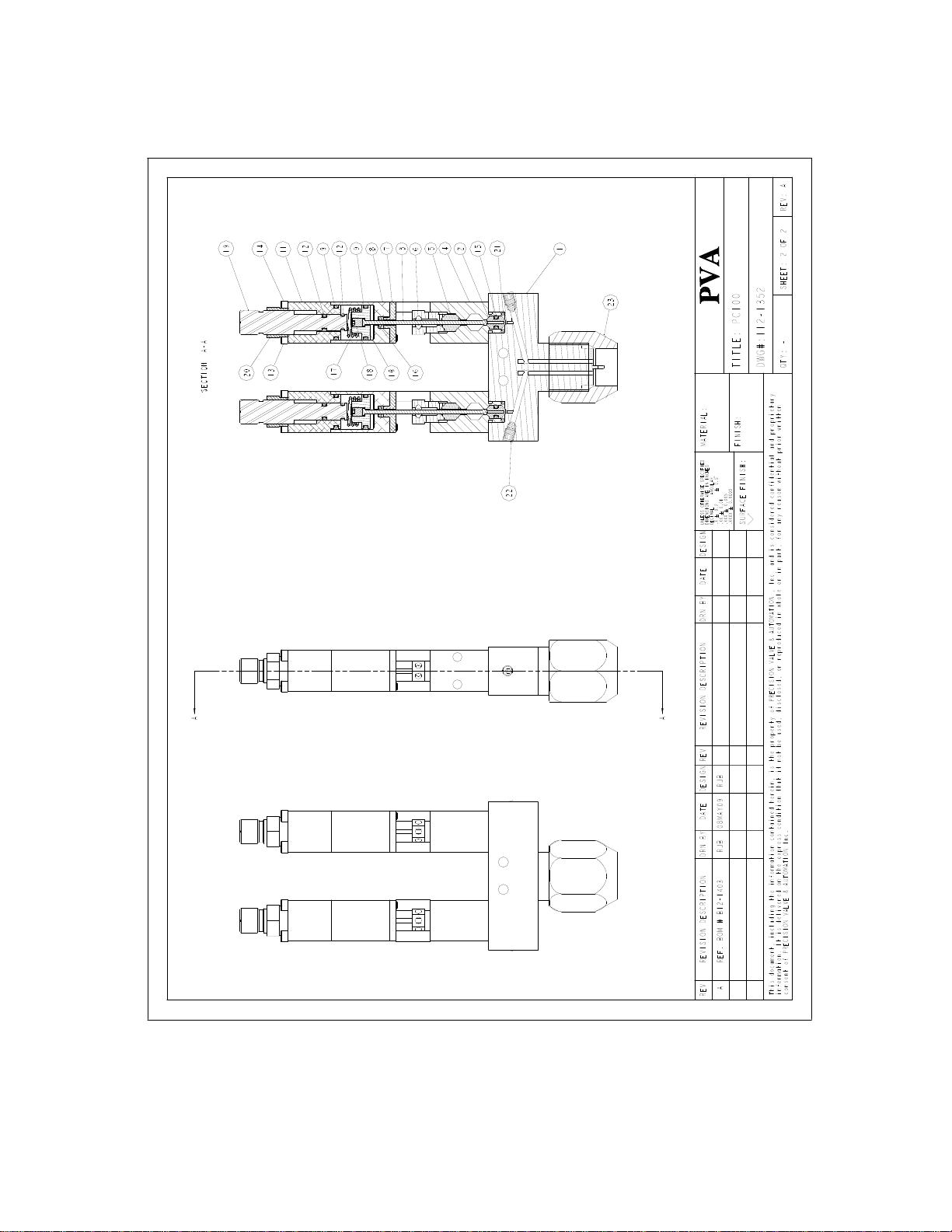
3) Remove the retaining nut (23) and dispose of the static mixer.
4) Using the tip of a 3/32” Allen key, loosen both packing nuts (6).
5) Using the same 3/32” Allen key, evenly remove the four machine screws (13) that
are located on the same corners as the standoffs (4). Note during removal that
there are springs (17) forcing the air sections away from the fluid section.
6) Pull the air sections (red anodized portions) away from the fluid section (stainless
steel portion).
7) Clean off the tip of the stainless steel needles (3).
8) From the fluid section of the valve, unthread and remove the packing nuts (6), and
the packing’s (5).
9) Using a 3/32” Allen Key, remove the eight machine screws (24) that hold the
fluid sections (4) to the manifold (1) and separate the sections.
10)Remove the two 010 Kalrez o-rings (21) from the manifold (1).
11)Using pliers pull the seats (2) out of the fluid sections (4) and remove the 006
Kalrez o-rings (15) from the seats. Note: If stuck, the seats can be pushed through
from the opposite side of the fluid section.
12)Clean all of the wetted parts thoroughly with an appropriate solvent.
13)On the air sections, use a standard 3/32” Allen Key to evenly remove the final
four machine screws (14) that thread into the end caps (7). Note: During removal
that the springs (17) will force the air sections apart.
14)Separate the upper air bodies (11) from the lower air bodies (8) to remove the
springs (17) then slide the end caps (7) off of the needles (3).
15)Holding the lower air bodies (8) in one hand, grab the needles (3) and push the
needle and piston (10) assemblies out of the lower air bodies.
16)Remove the 004 Buna o-rings (16) from the lower air bodies (8).

17)Hold the pistons (10) with an adjustable wrench then use a 5/64” Allen key to
unthread and remove the set screws (18) to remove the needles (3) then remove
the 014 Buna o-rings (9) from the pistons (10).
18)Remove the 014 Buna o-rings (9) from the upper air bodies (11) and the 008 Buna
o-rings (12) from the stroke adjust bolts (19).
19)Unthread the stroke adjust bolts (19) from the upper air bodies (11) and remove
the 008 Buna o-rings (12).
•Replace components with spares provided in the spare parts kit.
Assembly Instructions
General
•All o-rings must be lubricated with a small amount of silicone grease.
•A small amount of removable thread locker should be applied to the set screws (18)
and male ends of the standoffs (25).
•Assemble the air sections and fluid sections separately prior to connecting the two
assemblies.
Air Sections
1) Assemble the stroke adjust bolts (19) and lock nuts (20) with the hex head toward
the knurled end of the bolt.
2) Mount the first two 008 Buna o-rings (12) on the inside groove of the stroke
adjust bolts (19).
3) Thread the stroke adjustment assemblies into the upper air bodies (11).
4) Mount the first two 014 Buna o-rings (9) on the ends of the upper air bodies (11)
and the final two 008 Buna o-rings (12) on the end groove of the stroke adjust
bolts (19). Back out the stroke adjusts by turning them counter clockwise to the
end of their travel.
5) Drop the needles (3) into the pistons (10) and assemble with the set screws (18)
using an adjustable wrench and 5/64” Allen key to tighten.
6) Mount the final two 014 Buna o-rings (9) onto the pistons (10).
7) Apply a small amount of silicone grease to the inside of the lower air bodies (8)
then drop in the piston and needle assemblies.
8) Mount the 004 Buna o-rings (16) on the end of the needles and slide them down
into the groove in the end of the lower air bodies (8).
9) Slide the end caps (7) onto the needles up to the lower air bodies (8), place the
springs (17) on top of the pistons (10), and assemble the two air bodies using four
machine screws (14) tightening with a 3/32” Allen key. Note: Be sure the air
holes are lined up on the same faces and will align with the fluid inlet on the fluid
sections (4).

Fluid Section
1) Drop the packing’s (5) into the fluid sections (4), and screw in the packing nuts
(6) but leave finger tight until assembled with the air sections.
2) Thread the standoffs (25) into the fluid sections (4) and tighten using pliers with
soft grip ends.
3) Mount the 006 Kalrez o-rings (15) onto the seats (2) and push the seats into the
bottom of the fluid sections (4). When inserting the seats, work the o-ring into the
fluid body with finger to prevent shearing of the edge of the o-ring.
4) Place the 010 Kalrez o-rings (21) into the grooves on the top of the manifold.
5) Place the fluid sections (4) onto the manifold and assemble with the eight
machine screws (24) tightening with a 3/32” Allen Key.
*Note: Be sure the 1/8” fluid inlets will align on the face of the valve.
Assemble Sections
1) Back out the stroke adjust bolts (19) by turning them counter clockwise until the
end of their travel.
2) Apply a small amount of silicone grease to the end of the needles (3) and insert
them into the packing nuts (6) and slide the two sections together.
3) Align the air holes of the air sections on the same face as the 1/8”npt fluid inlets
of the fluid section then connect the sections using the four machine screws (13)
tightening them down evenly with a 3/32” Allen key.
4) Using the tip of a 3/32” Allen key, tighten the packing nuts (6).
Spare Parts
PVA offers standard spare parts kits for all dispensing valves. These kits are
stocked for immediate shipment and allow replacement of all wearable parts of the valve.
The spare parts kit for this valve, product number PC1-SP, includes the following
components:
PC1-SP Includes:
Qty
Part Number
Description
2
V302
Seat
2
114-5247
Needle
2
V305
Packing, Teflon
4
VLV-014B
O-ring, Buna
4
VLV-008B
O-ring, Buna
2
VLV-006K
O-ring, Kalrez
2
VLV-004B
O-ring, Buna
2
VLV-010K
O-ring, Kalrez


BILL OF MATERIALS FOR PC100 (B12-1403):
Refer to Drawing #: 112-1352 (1&2)
Item
Part Number
Description
Quantity
1
V325
Manifold
1
2
V302
Seat
2
3
114-5247
Needle
2
4
V304-PC
Fluid Section
2
5
V305
Packing
2
6
V306
Packing Nut
2
7
V200
End Cap
2
8
V201
Lower Air Body
2
9
VLV-014B
O-Ring, Buna
4
10
V202
Piston
2
11
V228
Upper Air Body
2
12
VLV-008B
O-Ring, Buna
4
13
SH5-40x2.0”
Cap Screw
4
14
SH5-40x2.25”
Cap Screw
4
15
VLV-006K
O-Ring, Kalrez
2
16
VLV-004B
O-Ring, Buna
2
17
V050
Spring
2
18
V001
Set Screw
2
19
V230
Stroke Adjust
2
20
V229
Lock Nut
2
21
VLV-010K
O-Ring, Kalrez
2
22
V007
Plug
2
23
165-38NWF
Retaining Nut for static mixer
1
24
SH5-40x1.0”
Cap Screw
8
25
V075
Standoff
4

Troubleshooting
Problem
Possible Cause
Corrective Action
Valve does not
cycle
- Air pressure to air section too low
- Packing nut is too tight
- Stroke adjustment bolt is bottomed
out
- Material is cured in the valve
- Valve was assembled w/o
lubricating the O-ring seals
- Increase air pressure to 60-100 psi
- Loosen packing nut until valve just
begins to cycle, retighten
- Back out stroke adjustment bolt by
turning it counter-clockwise
- Disassemble and clean valve
- Disassemble valve, lubricate seals and
re-assemble
Material leaks
from mixer
- Packing nut is too tight
- Needle and/or seat are worn
- Air bubble trapped in fluid body or
static mixer
- Loosen packing nut
- Replace parts as necessary
- Flip valve upside down and cycle
until air bubbles are removed
Valve leaks from
mid-section
- Packing nut is loose
- Packing is worn
- Tighten packing nut until snug
- Replace packing
Valve does not
dispense
anything
- Fluid pressure is too low
- Material cured in fluid section
- Stroke adjustment bolt is set too
low
- Increase fluid pressure
- Disassemble and clean valve
- Back out stroke adjustment bolt by
turning it counter-clockwise
Air bubbles in
fluid
- Valve not properly purged
- Problem with fluid delivery system
- Flip valve upside down and cycle
until air bubbles are removed
- Diagnose and repair.
Dispense rate too
fast
- Stroke Adjustment bolt set out too
far
- Turn stroke adjustment bolt clockwise
Dispense rate too
slow
- Stroke Adjustment bolt set in too
far
- Turn stroke adjustment bolt counter-
clockwise

PVA Warranty Policy
PVA warrants the enclosed product against defects in material or workmanship on
all components for one year from the date of shipment.
The warranty does not extend to components damaged due to misuse, negligence,
or installation and operation that is not in accordance with the recommended factory
instructions. Unauthorized repair or modification of the enclosed product, and/or the use
of spare parts not directly obtained from PVA (or from factory authorized dealers) will
void all warranties.
All PVA warranties extend only to the original purchaser. Third party warranty
claims will not be honored at any time.
Prior to returning a product for a warranty claim, a return authorization must be
obtained from PVA’s customer service department. Authorization will be issued either
via the telephone, facsimile, or in writing upon your request.
To qualify as a valid warranty claim, the defective product must be returned to the
factory during the warranty period. Upon return, PVA will repair (or replace) all
components found to be defective in material or workmanship.
(Retain this for your records)
Product Information:
PRODUCT: ______________________________
SERIAL NUMBER: ______________________________
DATE OF PURCHASE: ______________________________
Table of contents
Other PVA Control Unit manuals