PL-6N
BEDIENUNGSANLEITUNG
HANDNIETZANGE FÜR BLINDNIETMUTTERN M3-M6
UND BLINDNIETSCHRAUBEN M4-M6
TECHNISCHE INFORMATIONEN
Lieferumfang: Blindnietmuttern M3 - M4 - M5 - M6
Blindnietschrauben M4 - M5 - M6
Werksto: Aluminium, Stahl und Edelstahl
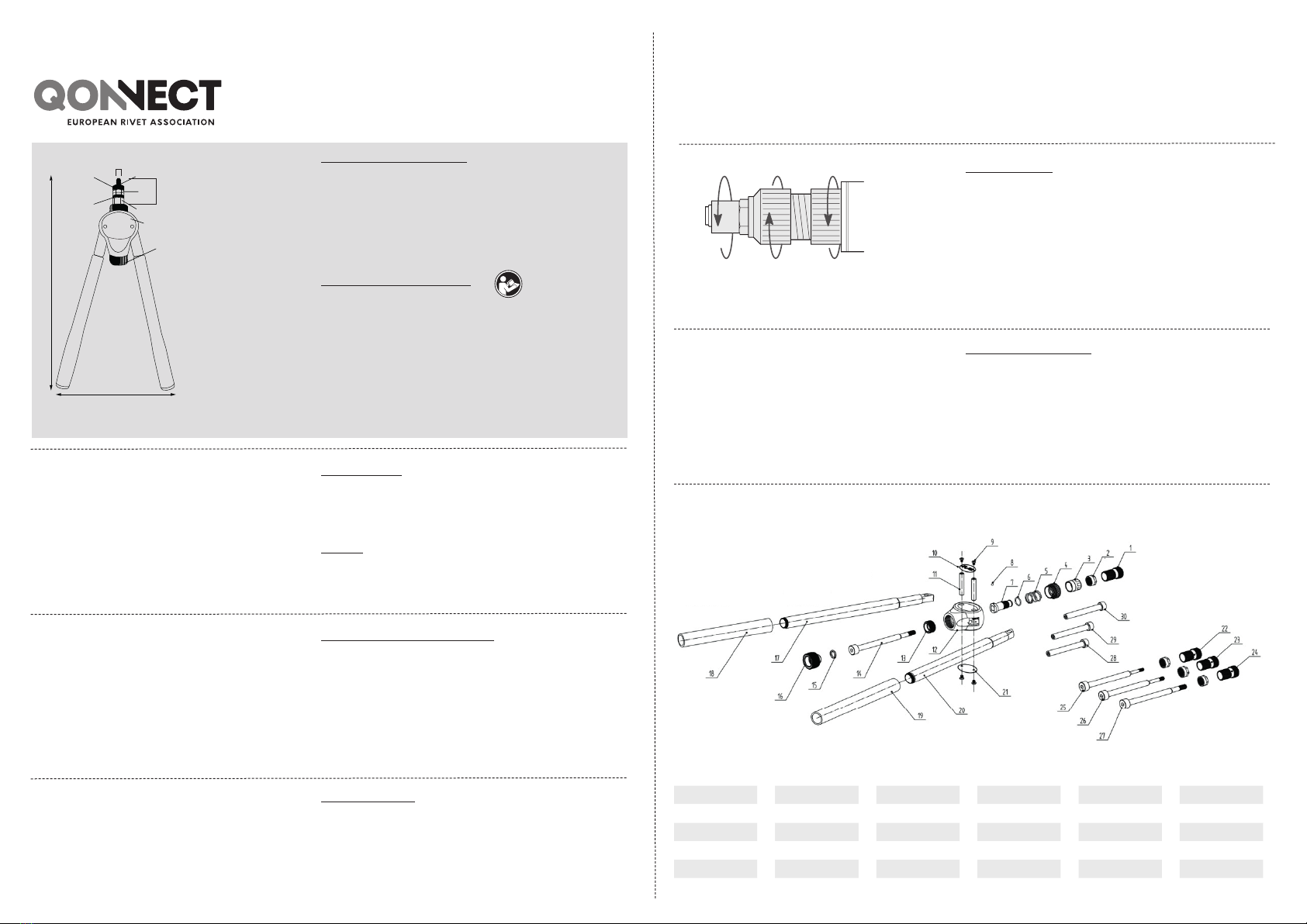
Abmessung: 380 mm (L) x 170 mm (H) 64 mm (P) 16 mm ()
Gewicht: 0,77 kg
BESCHREIBUNG
1. Werkzeuggehäuse
2. Linker und rechter Hebel
3. Drehknopf zum auf /ab spindeln
4. Gewindedorn
5. Mundstück
6. Kontermutter für Mundstück
7. Vordere Hülse mit Hubskala
8. Einstellmutter für Hubbegrenzung
Bedienungsanleitung lesen
ANWEISUNG
Die Handnietzange ist werksseitig mit einem Gewindedorn und
Mundstück M6 für Blindnietmuttern ausgerüstet.
Die Umrüstsätze M3-M4-M5 sind im Karton.
ERSTE BENUTZUNG:
Vergewissern Sie sich vor dem Gebrauch der Handnietzange dass der
richtige Umrüstsatz, entsprechend der Blindnietmutter/-schraube,
montiert ist. Andernfalls wechseln Sie in eine andere Abmessung.
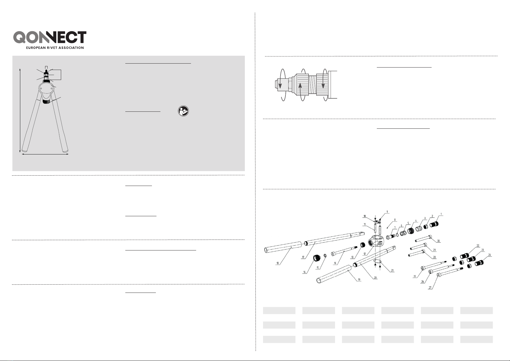
WECHSEL ZU EINER ANDEREN ABMESSUNG:
Lösen Sie die Kontermutter (6) und drehen Sie das Mundstück
(5) heraus. Nun den Gewindedorn (4) am Drehknopf (3) mit einer
Drehbewegung herausziehen. Wählen Sie den benötigten Umrüstsatz
und montieren Sie in umgekehrter Reihenfolge den Gewindedorn und
das Mundstück.
A
8
7
4
5
6
2 2
3
H
L
EINSTELLUNG DES MUNDSTÜCKS:
Nach der Hubeinstellung ist es wichtig das Mundstück (5) einzustellen
und mit der Kontermutter (6) zu sichern. Drücken Sie die Hebel
(2) vom Gehäuse (1) nach weg nach außen bis zum Anschlag, der
Gewindedorn ist nun in der vorderen Position. Die Blindnietmutter auf
den Gewindedorn drehen bis ein Gewindegang des Gewindedorns am
Schaftende der Blindnietmutter übersteht. Dann das Mundstück (5)
bis zum Anschlag gegen den Kopf der Blindnietmutter drehen. Mit der
Kontermutter ( 6) sichern.
C
SETZEN DER BLINDNIETMUTTER:
Drücken Sie die Hebel (2) vom Gehäuse (1) nach weg nach außen bis
zum Anschlag, der Gewindedorn ist nun in der vorderen Position. Nun
die Blindnietmutter auf den Gewindedorn des Werkzeuges drehen bis
zum Anschlag an das Mundstück. Die aufgeschraubte Blindnietmutter
mit dem Werkzeug in das vorbereitete Loch, entsprechend Vorgaben,
stecken. Den beide Handhebel (2) gegen das Gehäuse (1) drücken und
den Setzhub bis zum eingestellten Anschlag ausführen. Anschließend
den Gewindedorn mittels des Drehknopfes (3) herausdrehen. Prüfen
Sie den richtigen Sitz der Blindnietmutter/-Schraube und justieren Sie,
falls notwendig, den Hub entsprechend.
D
6 5
Handbuch PL-6N
HUBEINSTELLUNG:
Drücken Sie die beiden Handhebel (2) gegen das Gehäuse (1).
Drehen Sie die Hubbegrenzung (8) nach rechts (im Uhrzeigersinn),
um den Hub zu reduzieren. Durch die Verringerung des Hubes, wird
die Blindnietmutter/-schraube weniger verformt. Drehen Sie die
Hubbegrenzung (8) nach links (gegen den Uhrzeigersinn), um den
Hub zu erhöhen. Durch die Erhöhung des Setzhubes, wird die
Blindnietmutter/- schraube mehr verformt.
Der korrekte Hub ist abhängig von:
• Dem richtigen Klemmbereich
• Entsprechend der Materialstärke
• Der korrekten Blindnietmutter
B
Handbuch PL-6N
1
pull-link
1 04L00438 6 04F60037 11 04L20511 16 04Z20111 21 04L20507 26 04L20129
2 04P00435 7 04Z20901 12 04L20510 17 04Z20902 22 04L00434 27 04L20128
3 04L20121 8 04F00102 13 04L20803 18 04L20512 23 04L00436 28 04L20721
4 04L20122 9 04L21636 14 04L20127 19 04L20513 24 04L00437 29 04L20722
5 04L20875 10 04L20508 15 04F60166 20 04Z20903 25 04L20130 30 04L20723
P