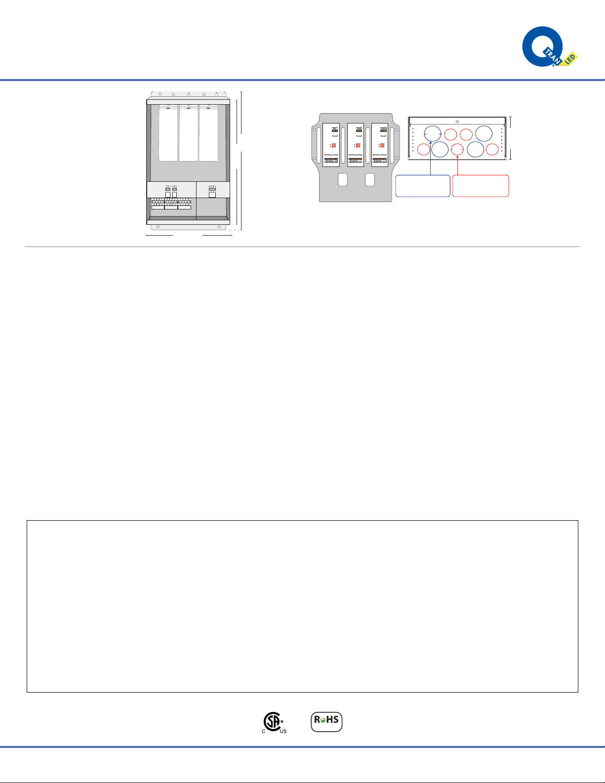
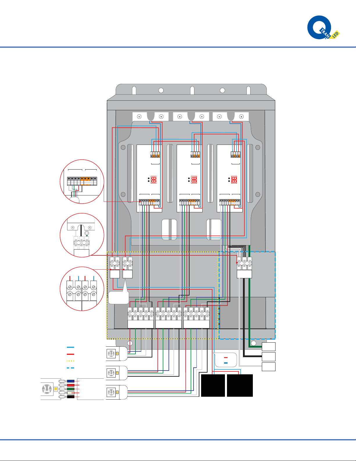
INSTALLATION LED POWER SUPPLY - QOM-eLED+DALI-DT8
©
2021
Q-T
ran
Inc.
All
rights
reser
ved
|
155
Hill
St.
Milf
ord,
CT
06460
|
203-367-8777
|
[email protected] |
www
.q-tran.com
Specification
subject
to
change.
Rev-11-15-22CSA Requirements
• Suitable for indoor use
• This power supply must be installed according to the National Electric Code and local codes and ordinances and in accordance with
applicable installation code by a person familiar with the construction and operation of the product and the hazards involved.
• Wear rubber shoes and work on a sturdy wooden or fiberglass ladder.
• This power supply is to be installed in a location where it is not likely to be contacted by non-electricians.
• To avoid a hazard to children, account for all parts and destroy all packaging materials.
Model Input Voltage
(V)
Frequency Nominal Output
Voltage (VDC)
Nominal Output
Wattage (W)
Input Current
(A)
QOM-eLED-100+DALI
QOM-eLED-200+DALI
QOM-eLED-300+DALI
120
120
120
0.95
1.90
2.85
50/60
50/60
50/60
24
24
24
100
200
300
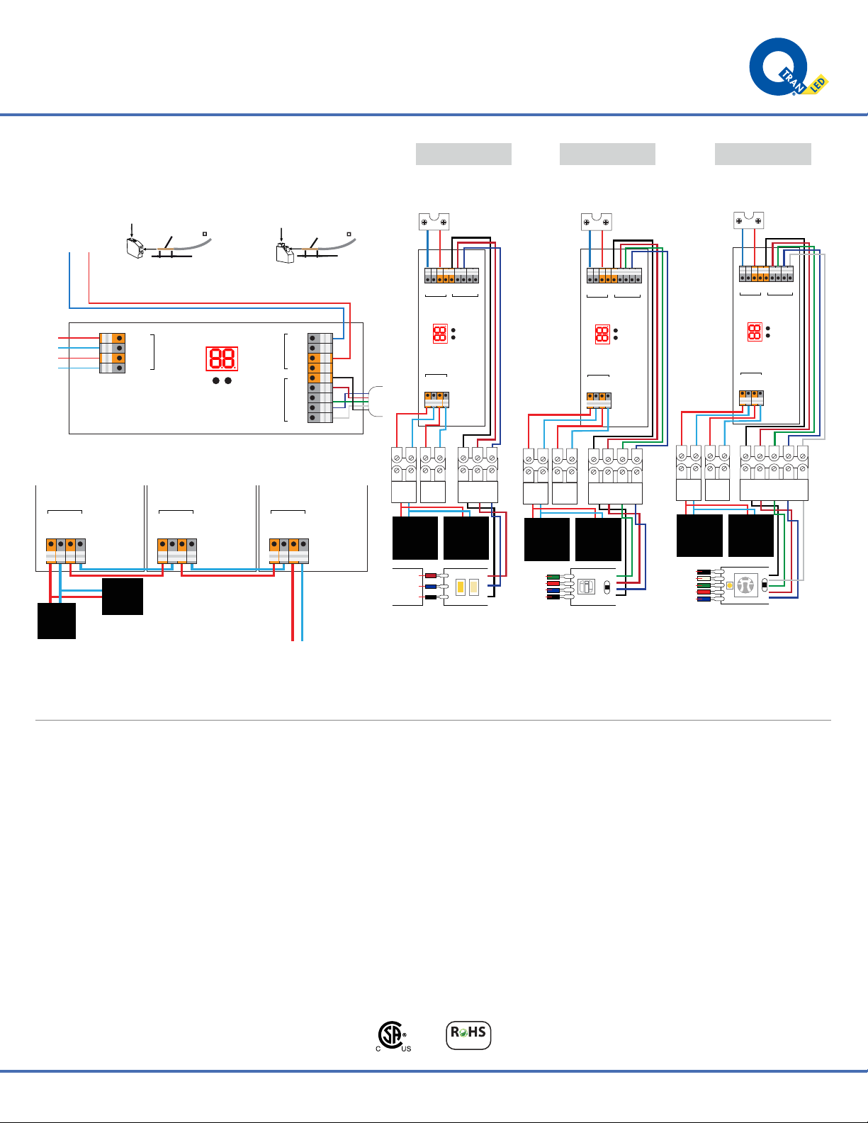
QOM-eLED+DALI
120V
INPUT VOLTAGE OUTPUT VOLTAGE
24V
CONTROL TYPE
DT8
DT624V
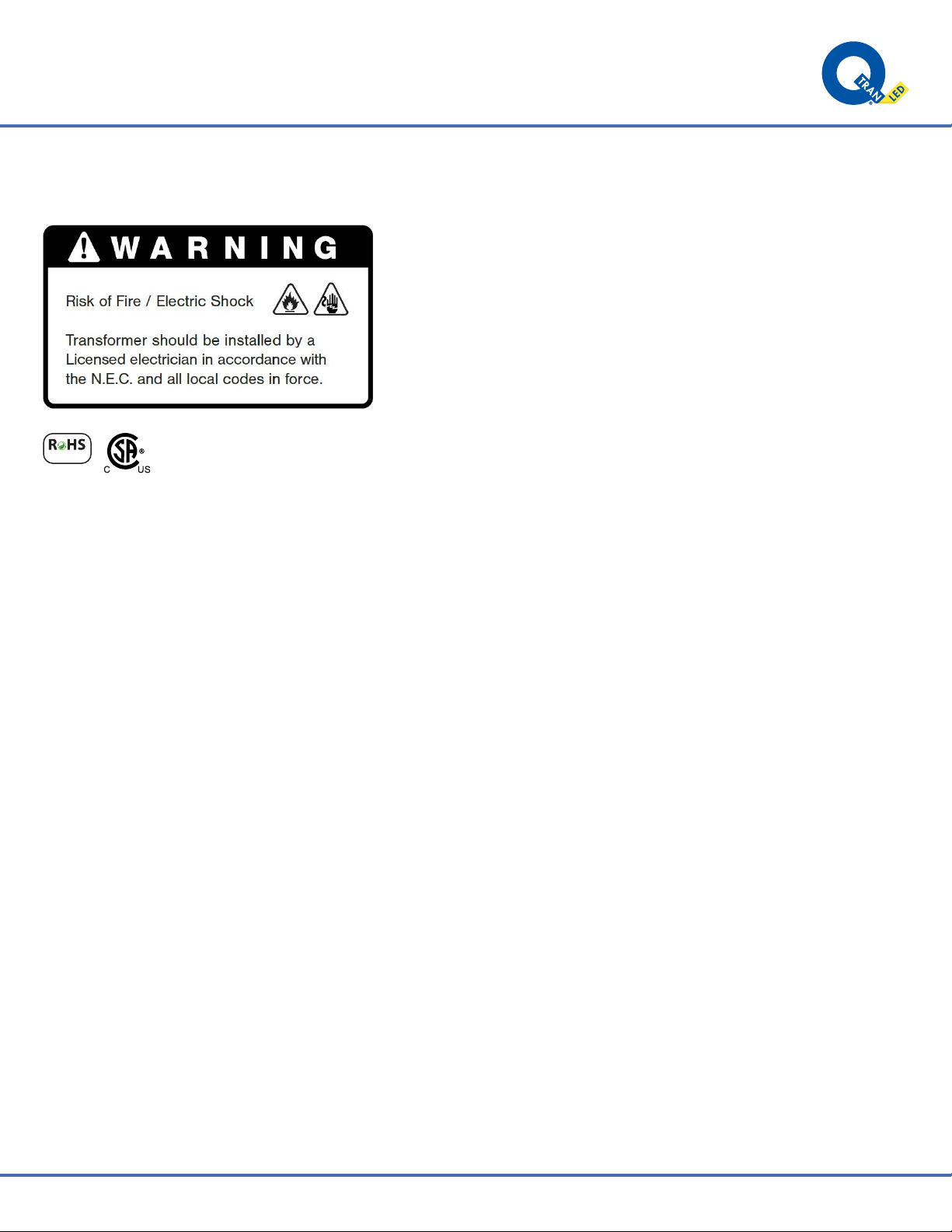
WARNING:
RISK OF FIRE. IF INSTALLATION INVOLVES RUNNING WIRE THROUGH
A BUILDING STRUCTURE, SPECIAL WIRING METHODS ARE NEEDED.
CONSULT A QUALIFIED ELECTRICIAN
RISQUE D'INCENDIE. SI L'INSTALLATION IMPLIQUE UN FIL DE COURANT À
TRAVERS UNE STRUCTURE DE BÂTIMENT, DES MÉTHODES DE CÂBLAGE
SPÉCIALES SONT NÉCESSAIRES. CONSULTEZ UN ÉLECTRICIEN QUALIFIÉ
This product must be installed in accordance with the applicable installation
code by a person familiar with the construction and
operation of the product and the hazards involved.
CE PRODUIT DOIT ÊTRE INSTALLÉ SELON LE CODE D'INSTALLATION
PERTINENT, PAR UNE PERSONNE QUI CONNAÎT BIEN LE PRODUIT ET
SON FONCTIONNEMENT AINSI QUE LES RISQUES INHÉRENTS.
Q-TRAN, INC.
MILFORD, CT U.S.A.
(203) 367-8777
WWW.Q-TRAN.COM
Suitable for indoor or outdoor use
Convient pour une utilisation intérieure ou extérieure
Wall mount only
Installation murale seulement
Suitable for mounting within 1.2m (4ft) of the ground
Peut être installé à moins de 1.2 m (4 pi) du sol
Suitable for use with submersible luminaires or submersible pumps
Convient pour une utilisation avec des luminaires submersibles ou
des pompes submersibles
Suitable for wet locations
Convient aux emplacements mouillé
CAUTION: This control unit has more than one power supply point
disconnect all power supplies before servicing
ATTENTION: Cette unité de contrôle a plus d'un point d'alimentation
débranchez toutes les alimentations avant l'entretien
For supply connections use wire rated for at least 60°C.
Pour les connexions d'alimentation, utilisez un fil évalué au moins À 60°c.
Keep Enclosure Cover Closed
Gardez le couvercle du boîtier fermé
Read Installation Instructions Before Wiring
Lire les instructions d'installation avant le câblage
Do not connect two or more power supplies in parallel
Ne connectez pas deux alimentations ou plus en parallèle
Class 2
Classe 2
●
●
●
●
●
●
●
●
●
●
●
LOW VOLTAGE LIGHTING SYSTEM
CLASS: 3425 - 15 3425 - 95
LED LANDSCAPE LIGHTING SYSTEM
CLASS: 3402 - 15 3402 - 95
Model Input Voltage
(V)
Frequency Nominal Output
Voltage (VDC)
Nominal Output
Wattage (W)
Input Current
(A)
QOM-eLED-100+DALI
QOM-eLED-200+DALI
QOM-eLED-300+DALI
120 / 277
120 / 277
120 / 277
0.95 / 0.40
1.90 / 0.80
2.85 / 1.20
50/60
50/60
50/60
24
24
24
100
200
300
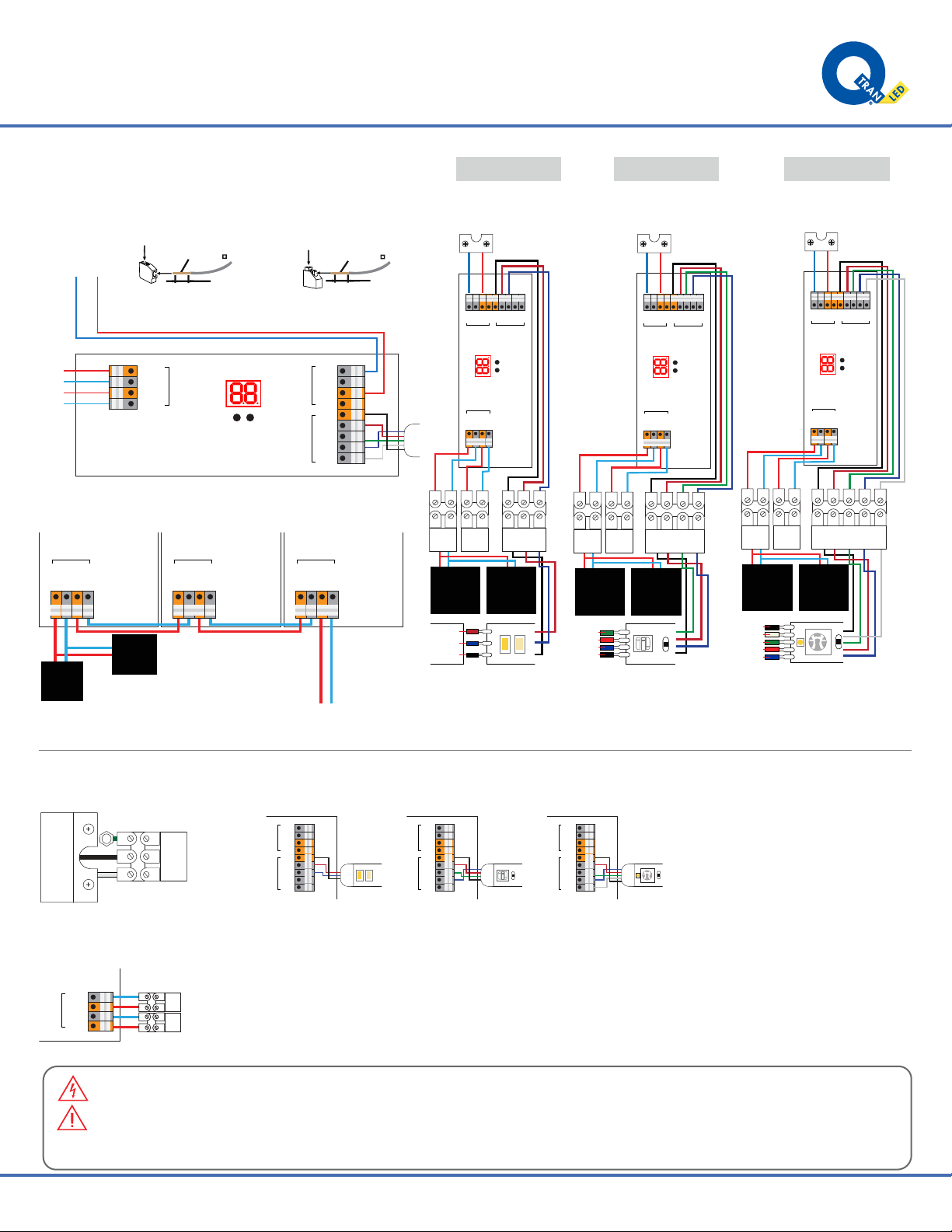
QOM-eLED+DALI
120V-277V
INPUT VOLTAGE OUTPUT VOLTAGE
CONTROL TYPE
DT8
DT6
24V
WARNING:
RISK OF FIRE. IF INSTALLATION INVOLVES RUNNING WIRE THROUGH
A BUILDING STRUCTURE, SPECIAL WIRING METHODS ARE NEEDED.
CONSULT A QUALIFIED ELECTRICIAN
This product must be installed in accordance with the applicable installation
code by a person familiar with the construction and
operation of the product and the hazards involved.
Q-TRAN, INC.
MILFORD, CT U.S.A.
(203) 367-8777
WWW.Q-TRAN.COM
Suitable for indoor or outdoor use
Wall mount only
Suitable for mounting within 1.2m (4ft) of the ground
Suitable for use with submersible luminaires or submersible pumps
Suitable for wet locations
CAUTION: This control unit has more than one power supply point
disconnect all power supplies before servicing
For supply connections use wire rated for at least 60°C.
Keep Enclosure Cover Closed
Read Installation Instructions Before Wiring
Class 2
●
●
●
●
●
●
●
●
●
●
LOW VOLTAGE LIGHTING SYSTEM
CLASS: 3425 - 95
LED LANDSCAPE LIGHTING SYSTEM
CLASS: 3402 - 95