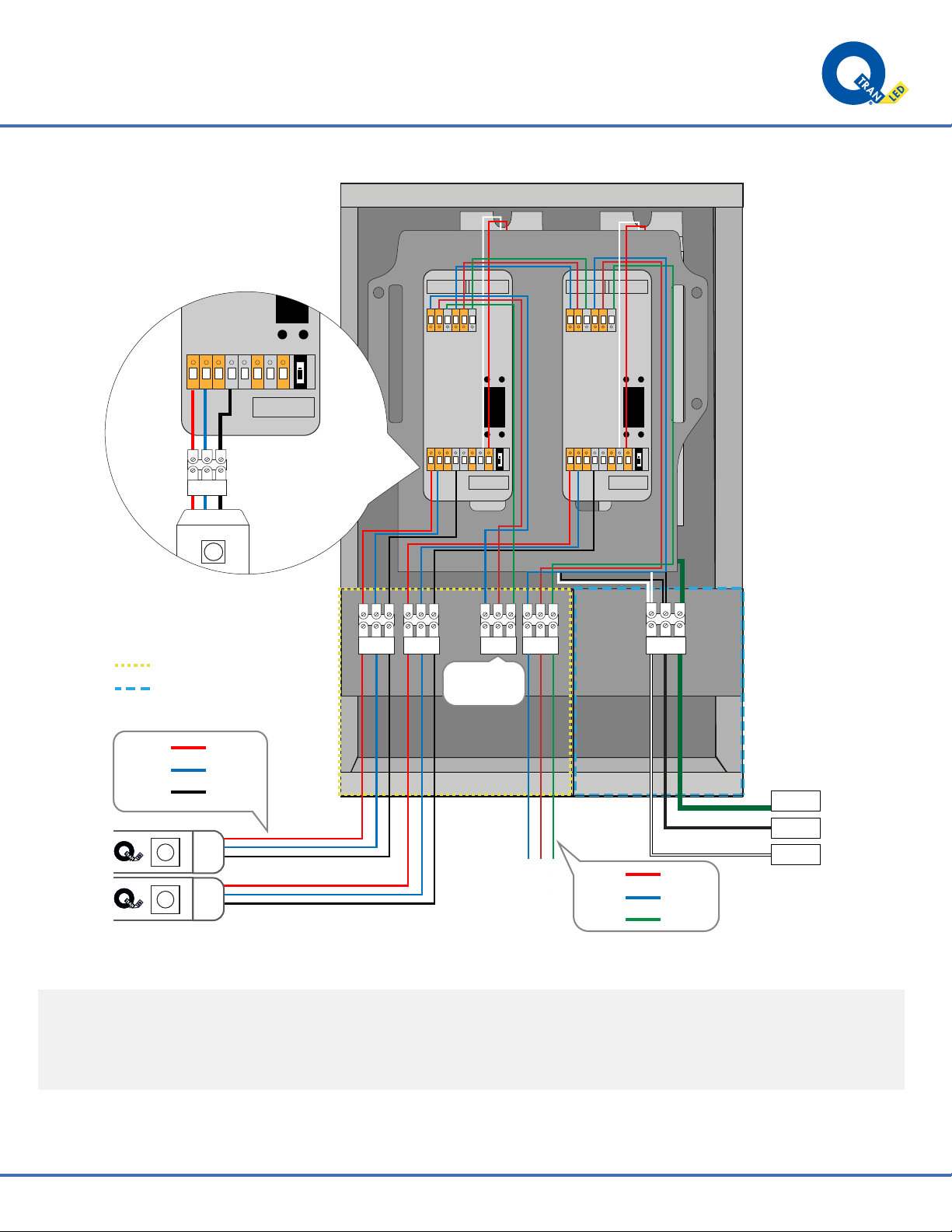
INSTALLATION LED POWER SUPPLY - QOM-eLED+IA
©
2020
Q-T
ran
Inc.
All
rights
reser
ved
|
155
Hill
St.
Milf
ord,
CT
06460
|
203-367-8777
|
[email protected] |
www
.q-tran.com
Specification
subject
to
change.
Rev-09-29-20
D-
GND
GND
D+
D-
D+
DMX INPUT DMX OUTPUT
POWE R
INPUT
SPI SIGNAL
CLK
DATA
POWE R
OUTPUT
12-24V
5V
P
Up
Down
Menu
Enter
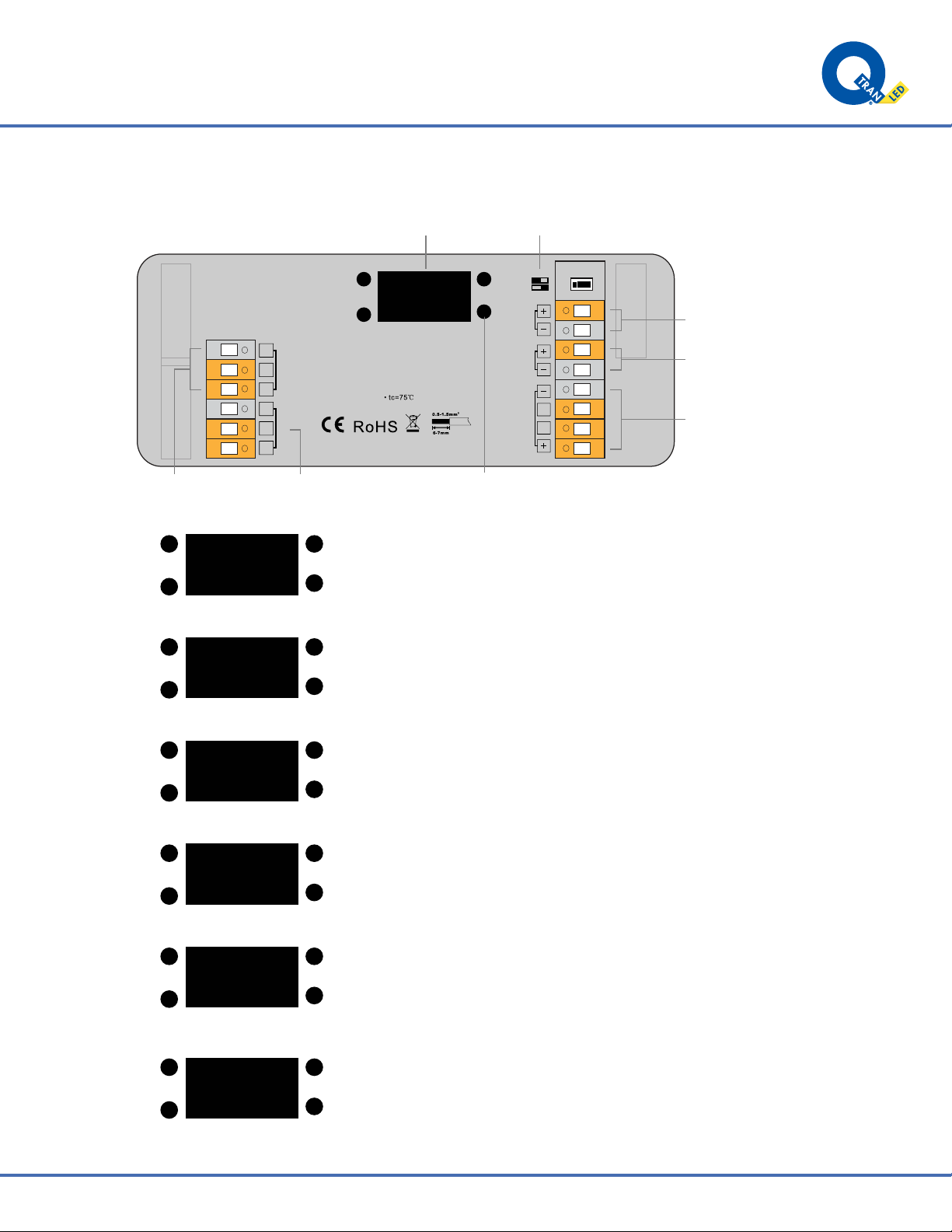
RI:
Uin=5-24VDC
Iin=0.2A Max
SEC:
Uout=SPI Signal TEMP RANGE:-20℃-+50℃
DMX512 signal input DMX512 signal output Learning button
DO NOT USE CLK
DC power input
OLED panel
DC power output
Connect with digital
IC LED lights
●Please check the operation voltage of
LED strip and confirm the input voltage
●Do not change while powered
●All Q-TRAN products are 12V or 24V
There are four buttons for configuration of settings with the OLED display:
“Menu,” “Enter,” “Up” and “Down,” Click “Menu” button to enter the menu
selection interface, and keep clicking “Up” and “Down” buttons you will get
5 settings one by one as follows:
Up
Down
MENU Select
>1 set mode
2 IC config
3 LED type
Up
Down
1 set mode
>1:DMX mode
2:RF mode
1. Set mode: to select an operation mode, click “Enter” button to enter the
configuration interface, then click “Up” or “Down” buttons to choose DMX mode,
click “Menu” button to confirm the setting and return to menu selection interface.
This setting should be in DMX mode for use with a DMX controller.
Up
Down
2 IC config
>1:TM1812
2:WS2801
3:WS2812e
2. IC config: to set driving IC type, click “Enter” button to enter the configuration
interface, click “Up” and “Down” buttons to choose an IC type that drives your LED
lights, click the “Menu” button to confirm and return to menu selection interface. Total 34
kinds of driving IC available. This should be set to WS2811L for all Q-Tran IA
Products
Up
Down
3 LED type
>1:RGB
2:RBG
3:GRB
3. LED type: to set RGB/RGBW color order, click the “Enter” button to enter the configura-
tion interface, click “Up” and “Down” buttons to choose a color order, click the “Menu” button
to confirm and return to menu selection interface. Total 7 kinds of color order available. The
LED type should be RGB for SWIA, and RGB IA, while it should be RGBW for RGBW
IA or RGBA IA
Up
Down
4 DMX address
start: 000
end: 0600
4. DMX address: to set DMX address under DMX mode, click the “Enter” button to enter the
configuration interface, the cursor will be on the “hundreds” position of the start address, click
the “Up” and “Down” buttons to change the number, click the “Enter” button to confirm and
move the cursor to “tens” position and set, then “units” position, and then the end address,
and click the “Menu” button to confirm the setting and return to menu selection interface.
Should be set based on the number of addresses needed. 000 to 511 would allow
maximum length.
Up
Down
5 Output length
**
3060
5. Output length: to configure total output channels, click the “Enter” button to enter the
configuration interface, the asterisk is on the “thousands” position, click the “Up” and “Down”
buttons to change the number, click the “Enter” button to confirm and move the asterisk to
“hundreds” position and set, then “tens” position and “units” position, and click the “Menu”
button to confirm and return to menu selection interface. The SPI controller supports max.
3060 output channels. This should be set to 3060 to max to allow for longest control.