© 2020, Q-Tran Inc. 155 Hill St. Milford, CT06460. All rights reserved - 203-367-8777 - [email protected] - www.q-tran.com 2020-04-08-V1
PROJECT NAME DATE TYPE NOTECOMPANY
1
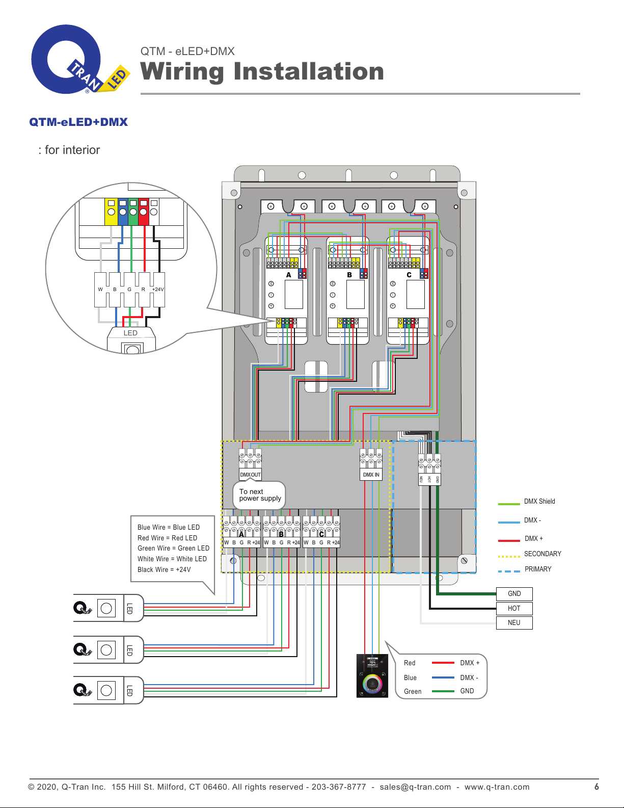
QTM-eLED+DMX
+DMX24
QTM-eLED UNV
2 Primary Voltage
UNV: 120-277 Vrms
3 Secondary Voltage
24VDC
DMX
DMX Opts
SizeModel Prim. V Sec. V
Max Prim.
@ 277V
1 Size Max Load
(Watts)
Max Prim.
Amps @ 120V
Max Prim.
Amps @ 277V
Secondary
Voltage(24VDC)
4 DMX
5 Options
WH White ( Standard )
QTM-eLED-100-UNV/24V+DMX
Ordering Example
ORDERING GUIDE
BK Black Powder Coat Finish
24VDC
24VDC
24VDC
0.95 A
1.90 A
2.85 A
0.40 A
0.80 A
1.20 A
1x100W
2x100W
3x100W
100W
200W
300W
M
-
+
M
-
+
M
-
+
TOP TRAY
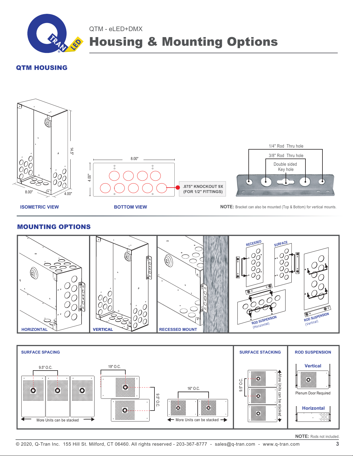
.875"
4.00"
9Knockouts of 0.875" Hole
for 1/2" fitting
HOUSING
● 18 gauge Welded Steel Enclosure: 14.5"W x 8.00"H x 4.00"D
● Door: 15.5"W x 9.00"H
● Knockouts: 25
● Built-in support bracket incorporated to secure housing for surface mounting
FEATURES
●Limited output voltage and current, plus isolation for safe operation
● Fully potted driver(s) for moisture resistance
● Controllable with DMX decoder module
● Control 4 LED channels with DMX
● Suitable for dry and damp locations
● Suitable for surface or recessed mounting use
● Primary Voltage - Universal (120-277V )
● Wide operating temperature range: -4 degF to 122 degF
● Fits up to (3):100W 24 VDC driver(s) and DMX decoder module(s)
● DMX dimming down to 0%
● Driver has Class A sound rating
● Class 2 Output
● 5 year warranty
● CSA #239924
Low Voltage Lighting Systems
: CSA Class 3425-15 and Class 3425-95
: CSA Standard C22.2 No. 250.0-08 - Luminaires
: ANSI/ UL Standard 2108 - Low Voltage Lighting Systems
: ANSI/ UL Standard 8750 - Light Emitting Diode (LED) Equipment for Use in Lighting Products
: CSA Std C22.2 No 250.13-14 - Light Emitting Diode (LED) Equipment for Lighting Applications
14.5"
8.00"
LED DRIVER B
(120V - 277V)
LED DRIVER A
(120V - 277V)
LED DRIVER C
(120V - 277V)
BOTTOM TRAY
PRIMARYSECONDARY
BOTTOM
NOTE: 16 additional side knockouts
CLASS: 3425 - 15
3425 - 95
LOW VOLTAGE LIGHTING SYSTEM
COMPLIANT
QTM-eLED is Q-Tran's interior rated surface or recess mounted
electronic DMX power supply, utilizing 100W constant voltage
LED Driver from Thomas Research. With the ability to fit up to
300W of power and control in one enclosure, this unit provides
plenty of flexibility and comes with all decoders prewired together
with terminal blocks for landing your RGB or RGBW wires.
A B C
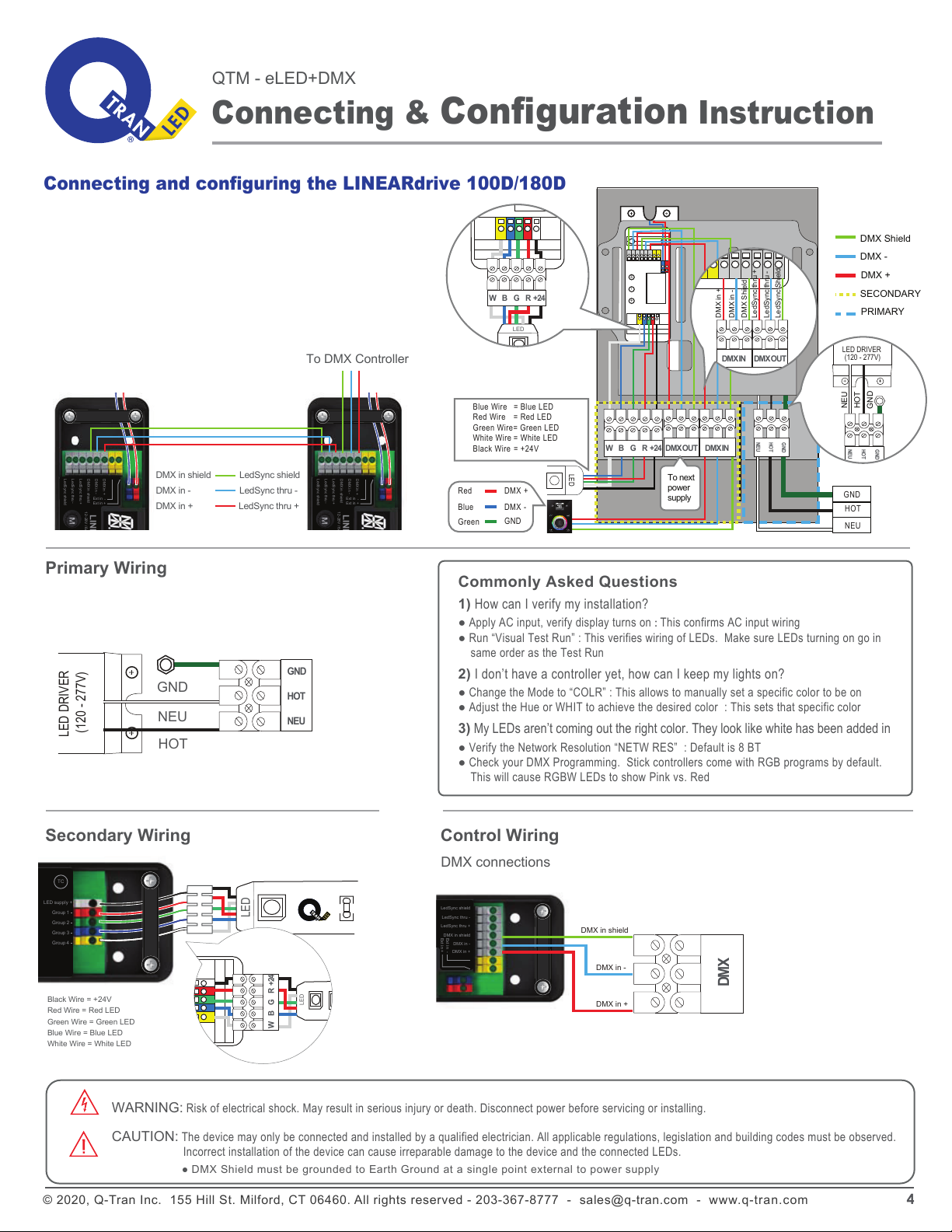
W B G R +24 W B G R +24 W B G R +24
DMX IN
NEU
HOT
GND
DMX OUT
A B C