R
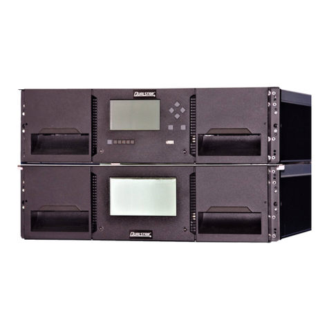
The Q80 libraries are expandable and accept add-on
components to enhance performance:
•
The library base modules come with one uninstalled tape
drive. Additional tape drives can also be installed. Always
install the drives from the bottom up.
•
Expansion library units can be added to the stack.
Once the library is secure in the rack, the additional items
should then be installed before hooking up the system. Follow
the instructions enclosed with the expansion unit.
Cable Attachment
All cabling, power connections and cooling are located on the
Q80’s rear panel.
Attach one end of the host interface cable to the library:
•
For a Serial Attached SCSI (SAS) connected library,
attach one end of the SAS cable to Port A (top) SAS
HBA on the SAS drive.
If you are using a SAS fanout/hydra cable, attach one
mini-SAS connector into the connector on each tape
drive. The unused ends of the SAS fanout cable are
single channel and not suitable for use with disk arrays.
Use the other ends to connect tape drives, or coil and
secure them to the rack to minimize stress on the
connectors.
•
For a Fibre Channel (FC) library, attach one end of the
fibre cable to Port A (top) connector on the FC drive,
removing the cap if necessary.
Atta
ch
th
e
o
t
h
er e
nd
of
t
he hos
t
in
t
er
f
ace cable as
f
ollows
:
•
For a SAS library, connect the host interface cable to
the host HBA, using a direct SFF-8088 connection.
Unused SAS connectors do not need termination.
If you are using a SAS fanout/hydra cable, the end of
the cable with only one connector should be plugged
into the HBA.
•
For a Fibre Channel library, connect the fibre cable to
the host or to a switch.
Plug the network Ethernet (management) cable into the
bottom Ethernet port (1) on the rear panel of the library.
If the Ethernet connection is directlyattached to a server or
laptop, a crossover Ethernet cable may be required.
NOTE: It is the customer'sresponsibilityto supply the
crossover cable if one is required.
For remote access, connect an Ethernet cable from the
bottom Ethernet port on the library module controller to
your network.
Plug the power cables into the power connectors on each
module and into power outlets (2).
NOTE: The library has dual redundant power supplies. To
increase availability, plug each power cord into an outlet
located on a different AC power circuit.
Power on the Library
The library can be operated using either the Operator Control
Panel (OCP) on the front of the device or remotely using the
Remote Management Unit (RMU) web interface.
Power on the library by pressing the power button on the
base module located just below the OCP; the green light
will illuminate. When the library is first powered on, it
inventories the tape cartridges in the magazines, checks
the firmware version on all modules, configures the tape
drives, confirms the presence of the existing modules, and
searches for any new modules.
