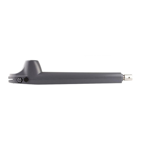
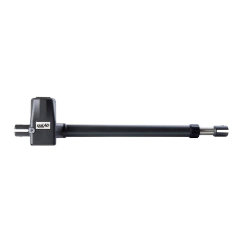
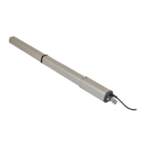
quiko HYDRO H300BAC User manual

battenti
I
T
A
L
I
A
N
O
HYDRAULIC OPERATOR FOR SWING GATES
u
s
e
a
n
d
m
a
i
n
t
e
n
a
n
c
e
m
a
n
u
a
l
HYDRO
E
N
G
L
I
S
H
V07/2017
NEW 2017 MODEL

50/60 Hz
yes
open-closed
yes
open-closed
Hydraulic lock
Slow travel Hydraulic slow down (only closing)
Rod stroke (MAX)
Rod linear speed
Traction / Thrust force to 15 bar
Pump flow-rate (l/m)
Hydraulic oil
Operating ambient
temperature
Protection class
Operator weight
Power supply
Absorbed power
Absorbed current
Electric motor (rpm)
Thermal protection
Capacitor
MODEL
Exploded View
H300BAC H400BAC

1.2. OPERATOR DESCRIPTION
ENGLISH
These instructions apply to the following models:
HYDRO.
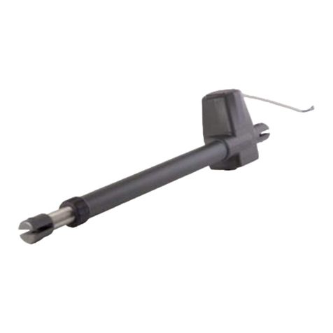
The HYDRO hydraulic operator for swing gate, they are constituted by an enbloc composed of an electric pump and a
hidraulic piston that transmits the movement to the the gate.
The HYDRO operator guarantees
mechanical locking of the leaf when the motor is not operating.
The hydraulic operator HYDRO is designed and produced to automate swing gates.
1. DESCRIPTION AND TECHNICAL SPECIFICATIONS
1.1. DIMENSIONS
DIMENSIONS (mm)
LENGTH (A)
Distance attacks (B)
Rod stroke (C)
1) Electric motor
2) Release lock
3) Hydraulic piston
4) Cylinder
5) By-pass valves
6) Pump
7) Electrical power cable
8) Front attack
9) Cover for stroke
10) Kit release
11) Rear attack
12) Rod end
2. ELECTRIC STANDARD DEVICES
1) Hydraulic operators
2) Photocells
3) Electronic control box
4) Key selector
5) Receiver
6) Flashing light
7) Electric lock
You needs always to separate the connecting cables
of the low voltage accessories from the 230 V.
Use separate sheaths to avoid any type of interference.
Connect power cables hydraulic operator:
- Co (Common) = gray cable
- Ap (open) = brown cable
- Ch (closing) = black cable
- T (earth) = yellow / green
3. INSTALLING SYSTEM
3.1. PRELIMINARY CHECKS OF THE GATE
For a correct operating gate must satisfy the following
conditions:
- robust and rigid structure of the leaves;
- the leaf movement should be smooth and uniform but without
any friction during the race;
- the hinges must be in excellent state;
- limit mechanical stops placed.
Any metalwork shall be conducted before installation of
automation.
The state of the gate structure influence the reliability and
safety of the automatism.
H300
H400

Fig. 1
Fig. 2
Fig. 3
Plate
to wall
Plate
attack
ENGLISH
3.2. HYDRAULIC OPERATOR INSTALLATION
A) Attach the rear mounting on the pillar and follow the signs of
Tables A and B, modify, if necessary, the length of the attack
(fig. 1).
Compliance with the dimensions shown in the above tables to
ensure the smooth operation of the automatism.
In the case of an iron pillar carefully weld the rear mounting
directly on the pier.
In the case of masonry opt for one of the following solutions:
1) Cash suitably a plate to wall, and then pay back the attack;
2) Fix to the pillar, with screws and dowel, the rear mounting
plate and weld the rear mounting plate (Fig. 2);
B)Attach the operator to the rear (Fig. 2);
C) Tighten the front end in the middle (rod) on the shaft and
tighten the nut (fig. 3);
D) Release the hydraulic operator; (Fig. 10)
E) Remove the chromed rod to the full bar;
F) Re-lock the hydraulic operator; (Fig. 10)
G) Install the front end on the stroke (Fig. 4);
H) Close the door of the gate and, keeping the operator in
perfectly level position, locate the position of a front on the
wing (Fig. 4);
I) Temporarily fasten the front attachment on the gate by two
spot welds (protect the stroke from any welding slag);
L) Release the hydraulic operator, make sure the gate is open
and free to stay on the mechanical stops to limit pre-installed
and verify that the movement of the gate is smooth and without
friction;
M) Remove the operator from its temporarily and permanently
weld the front attachment on the wing(Fig. 5);
N)Attach the cover rod hydraulic operator (Fig. 7);
O) Re-lock the hydraulic operator and to effectue the electrical
connections with the electronic equipment, according to the
instructions in the manual.
dimensions in mm.
distance attacks (*)
TABLE «A»:H300 - Fixing brackets
TABLE «B»:H400 - Fixing brackets
(*) rod stroke required to stem the slowdown in the closing
(**) max dimensions
hydraulic
In the case that the dimensions of the pilar or the position of the
hinge (dimension D) are not able to contain the dimension A as
it wishes, it is necessary to make a niche on the pillar (Fig. 6),
the dimension A must be always greater than the distance E.
OPENING
ANGLE
OPENING
ANGLE
(*) rod stroke required to stem the slowdown in the closing
(**) max dimensions
hydraulic

Fig. 4
Fig. 5
Fig. 6 Fig. 8
Fig. 7
ENGLISH
3.3. SPECIAL INSTALLING FOR HYDRAULIC OPERATOR
WITH OPENING GATE OUT (Fig. 8)
The mounting dimensions of the hydraulic operator is
detected by the following Table C.
In case of opening gate to the outside, adjust the anti-trap, as
follows:
- Screw A = valve regulation closing force,
- Screw B = valve regulation opening force.
To r educe the torque, you need to turn the screw
counterclockwise;
To increase the torque, you need to turn the screws clockwise.
TABLE «C»:H300 - Fixing brackets
OPENING
ANGLE
(*) rod stroke required without the hydraulic slowdown
(**) max dimensions
Length dimension A=50 mm
Length dimension B=+ 100 mm

4.1. SETTING ANTI-TRAP (fig.9)
4.3. AUTOMATISM TEST
5.2. AUTOMATED SYSTEM RESET
ENGLISH
4. ANTI-CRUSHING CONTROL SYSTEM
- FINAL OPERATIONS - TEST AUTOMATION
The hydraulic operators have a security anti-trap for
to control the hydraulic operator force, in the presence of an
obstacle during the movement of the gate.
The force is adjusted as follows:
- slide to unlock and lift the cap
- lift the base of the release
- to act on the control valves:
1) valve "A" to adjust the opening force
2) valve "B" to adjust the closing force
3) valve "C" to unlock it completely.
Turning the valve clockwise to increase torque, and
counterclockwise to decrease the torque.
The adjustment of the torque limiters,in EU member states,is
subject to standards EN 12445 and EN 12453.
In the other states is subject to local regulations.
4.2. FINAL OPERATION
After the adjusting anti-trap, follow these steps:
- close the device of the release
- remove the vent screw (Fig. 10).
After installation proceed with care to the test for verification
the automation functionality and all the accessories
connected with particular attention to security devices.
Give the "User Guide" to customer and explain the correct use
of the automated system and highlight areas of potential
danger from it.
5. MANUAL OPERATION AND RESET
5.1. MANUAL OPERATION
In case is necessary to manually operate the gate for absence
of electric tide or damage of the automation, you must be acted
on the device of unblocking as it follows:
- to open the cork of coverage unblocking and to insert the
special key in endowment;
- to rotate the key counterclockwise sense for to unlock;
- to effect manually the manoeuvre opening or closing of the
gate.
Before proceeding to the reset of the automated system, after
manual unblocking, it is advisable to disconnect the power
supply of the automatism, with the purpose to avoid that an
unintentional impulse can operate the automation.
The reset operation must be effected as it follows:
- to rotate the key of unblocking counterclockwise sense up to
the arrest;
- to close again the cork of coverage of the unblocking system;
- to insert again the power supply of the automation;
- to start the automation.
6. MAINTENANCE AND REPAIR
6.1. MAINTENANCE
In case of oil topping up must be strictly used Total oil
52-AT42
Periodically check the proper adjustment of the anti-crushing
safety (valve regulating power) and efficiency of the release
system.
The functional verification of the plant is recommended every
six months, with particular attention to the efficiency of the
safety devices and unblocking, included the verification of the
thrust force of the hyfraulic operator; it is also well to verify the
degree of functionality of the hinges of the gate.
Check the level oil inside the oil tank.
6.2. REPAIR
The possible reparations on the automation must be effected
exclusively from specialized personal, possibly authorized.
To use original spare parts.
7. TROUBLESHOOTING
Gate not moving
Gate moving slowly
Gate moving to tears
Oil leakage from the vent screw
Stop leaves at slow down
Rod stroke variable speed
- control power supply
- check that the operator is released
- check adjustment anti-crushing system
- check oil level in the tank
- check efficiency capacitor
- check efficiency of the electronic control unit.
- check adjustment anti-crushing system
- Verify the removal of the bleed screw oil
- to eliminate possible air in the hydraulic circuit,
effecting complete cycles of opening
and closing of the gate
- It is normal for a minimum initial oil leakage,
if theoil leakage is continuing, verify the perfect
horizontal position of the hydraulic operator.
Otherwise, contact an authorized personal.
- check adjustment anti-crushing system
- to verify the quotas of the angle opening
olio
Fig. 9
A
B
apertura
chiusura
Release control valve fully open
Control valve
closing force
Control valve
opening force
Oil distributor
Fig. 10
Oil vent screw

DECLARATION OF CONFORMITY
(OF THE MANUFACTURER)
Manufacturer: QUIKO ITALY SAS
hereby declares, under his liability, that products:
QK-H300BAC
are in compliance with the essential safety requirements of the regulations:
Electro-magnetic Compatibility Directive .........................2004/108/EC
Low Voltage Directive ......................................................2006/95/EC
Machinery Directive .........................................................2006/42/EC
and their amendments and modifications, and with the regulations set forth by the
National Legislative Body of the country in which the machinery is destined for use.
Via Seccalegno, 19
36040 Sossano (VI)
Italia
QK-H400BAC
Managing Directo r
Luca Borinato
Sossano, 19/01/2017

QUIKO ITALY
Via Seccalegno, 19
36040 Sossano (VI) - Italy
Tel. +39 0444 785513
Fax +39 0444 782371
info@quiko.biz
www.quikoitaly.com

battenti
I
T
A
L
I
A
N
O
OPERATORE OLEODINAMICO PER CANCELLI A BATTENTE
HYDRO
V07/2017
NUOVO MODELLO 2017
Manuale
d’installazione
e
d’uso
I
T
A
L
I
A
N
O

ITALIANO
MODELLO
Blocco Idraulico
in apertura
in chiusura
in apertura
in chiusura
Rallentamento corsa Idraulico solo in chiusura
Corsa stelo
(MAX)
mm 270
1,3 cm./sec.
mm 390
Velocità lineare stelo
Forza di spinta / trazione a 15 bar
220 Kg. (2240 N)
Portata pompa (l/m)
Total 52-AT42
1
Olio idraulico
Temperatura ambiente
di esercizio - 25° C + 70° C
Grado di protezione IP 55
9 Kg. 10 Kg.
Peso attuatore
Tensione di alimentazione 230 V ac (+6% - 10%) 50/60Hz
Potenza assorbita 250 W
1400
250 W
Corrente assorbita 1 A 1 A
Motore elettrico (giri/min.)
Termoprotezione motore 120° C
10 µF
Condensatore di spunto 10 µF
Caratteristiche tecniche
QK-H300BAC QK-H400BAC
Vista esplosa
220 Kg. (2240 N)

Le presenti istruzioni sono valide per i seguenti modelli:
HYDRO
Gli attuatori oleodinamici HYDRO per cancelli a battente sono costituiti da un monoblocco composto da una elettropompa
ed un pistone oleodinamico che trasmette il movimento all’anta del cancello.
I modelli dotati di blocco idraulico non necessitano l’installazione di elettroserrature, garantendo il blocco meccanico
dell’anta del cancello quando l’attuatore non è in funzione.
Gli attuatori oleodinamici HYDRO sono stati progettati e costruiti per l’automazione di cancelli a battente; evitare qualsiasi
altro utilizzo.
Per un corretto funzionamento dell’automazione, il cancello
deve possedere i seguenti requisiti:
- struttura robusta e rigida delle ante;
- il movimento delle ante deve essere regolare ed uniforme ma
anche privo di attriti durante la corsa;
- le cerniere devono essere in ottimo stato;
- arresti meccanici di fine corsa posizionati.
Eventuali interventi fabbrili devono essere effettuati prima
dell’installazione dell’automazione.
Lo stato della struttura del cancello influenza l’affidabilità e la
sicurezza dell’automazione.
2. SCHEMA IMPIANTO ELETTRICO STANDARD
3. INSTALLAZIONE DELL’ATTUATORE
1.2. DESCRIZIONE ATTUATORE
3.1. VERIFICHE PRELIMINARI DEL CANCELLO
ITALIANO
1. DESCRIZIONE E CARATTERISTICHE TECNICHE
1.1. DIMENSIONI
MODELLO
Lunghezza (A)
H300 270
H400
Interasse attacchi (B)
Corsa stelo (C)
DIMENSIONI (mm)
1330 825 390
1090 705

3.2. FISSAGGIO ATTUATORE
ITALIANO
A) Fissare l’attacco posteriore sul pilastro seguendo le
indicazioni delle tabelle A e B, modificare, se necessario, la
lunghezza dell’attacco in dotazione (fig. 1).
Il rispetto delle quote indicate nelle citate tabelle garantisce il
buon funzionamento dell’automazione.
Nel caso di pilastro in ferro saldare accuratamente l’attacco
posteriore direttamente sul pilastro.
Nel caso di pilastro in muratura optare per una delle seguenti
soluzioni:
1) Incassare opportunamente una piastra a murare e quindi
saldare l’attacco posteriore;
2) Fissare al pilastro con viti e tasselli la piastra attacco
posteriore e saldare l’attacco posteriore sulla piastra (fig. 2);
B) Fissare l’attuatore all’attacco posteriore (fig.2);
C) Avvitare a metà l’attacco anteriore (testa a snodo) sullo
stelo e serrare con il dado in dotazione (fig. 3);
D) Sbloccare l’attuatore oleodinamico; (fig. 10)
E) Estrarre lo stelo cromato fino a totale battuta;
F) Ribloccare l’attuatore; (fig. 10)
G) Montare l’attacco anteriore sullo stelo (fig.4);
H) Chiudere l’anta del cancello e, mantenendo l’attuatore
perfettamente orizzontale, individuare sull’anta la posizione
dell’attacco anteriore (fig. 4);
I) Fissare provvisoriamente l’attacco anteriore sull’anta del
cancello tramite due punti di saldatura (proteggere lo stelo da
eventuali scorie di saldatura);
L) Sbloccare l’attuatore, verificare che il cancello
manualmente sia libero di aprirsi e fermarsi sugli arresti
meccanici di fine corsa preinstallati; verificare inoltre che il
movimento dell’anta del cancello sia regolare e privo di attriti;
M) Staccare momentaneamente l’attuatore dall’attacco e
saldare definitivamente l’attacco anteriore sull’anta (fig. 5);
N) Applicare il copri stelo sull’attuatore (fig. 7);
O) Ribloccare l’attuatore ed effettuare i collegamenti
elettrici con l’apparecchiatura elettronica, secondo le
istruzioni riportate nel relativo manuale.
Nel caso che le dimensioni del pilastro o la posizione della
cerniera (quota D) non permettano di contenere la quota A
nella misura desiderata, è necessario effettuare una nicchia
sul pilastro (fig. 6); la quota A deve essere sempre maggiore
della quota E.
Fig. 1
Fig. 2
Fig. 3
Piastra a
murare
Piastra
attacco

3.3. FISSAGGIO ATTUATORE CON APERTURA
CANCELLO VERSO L’ESTERNO (g. 8)
ITALIANO
Le quote di fissaggio dell’attuatore si rilevano dalla seguente
tabella C.
La regolazione del sistema antischiacciamento, in caso di
apertura cancello verso l’esterno, si effettua come segue:
- vite A = valvola di regolazione forza in chiusura;
- vite B = valvola di regolazione forza in apertura.
Per diminuire la coppia è necessario ruotare le viti in senso
antiorario, invece per aumentare la coppia è necessario
ruotare le viti in senso orario.
Fig. 4
Fig. 5
Fig. 6 Fig. 8
Fig. 7

4.1. REGOLAZIONE SISTEMA ANTISCHIACCIAMENTO (fig.9)
ITALIANO
L’attuatore oleodinamico èdotato di una sicurezza
antischiacciamento che limita la forza dell’attuatore stesso, in
presenza di un ostacolo durante il movimento del cancello.
La forza si regola come segue:
- fare scorrere il tappo di sblocco e sollevarlo;
- sollevare la base del gruppo di sblocco;
- agire sulle valvole di regolazione: valvola “A” per regolare la
forza in apertura, valvola “B” per regolare la forza in chiusura e
valvola “C” per sbloccare totalmente.
Ruotando le valvole in senso orario si aumenta la coppia,
mentre in senso antiorario si diminuisce la coppia.
La regolazione dei limitatori di coppia, negli stati dell’Unione
Europea, è soggetta alle norme EN 12445 e EN 12453. Negli
altri stati è soggetta alle norme locali vigenti.
4. REGOLAZIONE SISTEMA ANTISCHIACCIAMENTO
- OPERAZIONI FINALI - PROVA AUTOMAZIONE
4.2. OPERAZIONI FINALI
Terminate le operazioni di regolazione del sistema
antischiacciamento, operare come segue:
- richiudere il dispositivo del gruppo di sblocco;
- rimuovere la vite di sfiato (fig. 10).
4.3. PROVA AUTOMAZIONE
Terminata l’installazione, procedere con cura alla verifica
funzionale dell’automazione e di tutti gli accessori collegati
con particolare attenzione ai dispositivi di sicurezza.
Consegnare al titolare dell’impianto la “Guida per l’utente” ed
illustrare il corretto funzionamento ed utilizzo del sistema
automatizzato ed evidenziare le zone di potenziale pericolo da
esso derivanti.
5. FUNZIONAMENTO MANUALE E RIPRISTINO
5.1. FUNZIONAMENTO MANUALE
In caso sia necessario azionare manualmente il cancello per
assenza di corrente elettrica o avaria dell’automazione, si
deve agire sul dispositivo di sblocco come segue:
- aprire il tappo di copertura sblocco ed inserire l’apposita
chiave in dotazione;
- ruotare la chiave in senso antiorario per sbloccare;
- effettuare manualmente la manovra di apertura o chiusura
dell’anta del cancello.
5.2. RIPRISTINO SISTEMA AUTOMATIZZATO
Prima di procedere al ripristino del sistema automatizzato, a
seguito sblocco manuale, è consigliabile disinserire
l’alimentazione elettrica dell’impianto, al fine di evitare che un
impulso involontario possa azionare l’automazione.
L’operazione di ripristino va effettuata come segue:
- ruotare la chiave di sblocco in senso orario fino all’arresto;
- richiudere il tappo di copertura del sistema di sblocco;
- reinserire l’alimentazione elettrica dell’impianto;
- avviare l’automazione.
6. MANUTENZIONE E RIPARAZIONE
E’ consigliata la verifica funzionale dell’impianto ogni sei mesi,
con particolare attenzione all’efficienza dei dispositivi di
sicurezza e di sblocco, inclusa la verifica della forza di spinta
dell’attuatore; è bene anche verificare il grado di funzionalità
delle cerniere del cancello.
Controllare altresì il livello dell’olio all’interno del serbatoio.
6.1. MANUTENZIONE
In caso di rabbocco d’olio si deve tassativamente usare
olio Total 52-AT42
Verificare periodicamente la corretta regolazione della
sicurezza antischiacciamento (valvole regolazione forza) e
l’efficienza del sistema di sblocco.
Le eventuali riparazioni sull’impianto automatico devono
essere effettuate esclusivamente da personale specializzato,
possibilmente autorizzato
Utilizzare ricambi originali.
6.2. RIPARAZIONE
7. INDIVIDUAZIONE GUASTI
Il cancello non si muove
- controllo alimentazione elettrica di rete
- verificare che l’operatore non sia sbloccato
- controllare valvole regolazione di forza
- verificare livello olio nel serbatoio
- verificare efficienza condensatore di spunto
- verificare funzionalità centralina elettronica
- controllo regolazione sistema antischiacciamento
Il cancello si muove lentamente
Il cancello si muove a strappi
- verificare la rimozione della vite di sfiato olio
- eliminare eventuale aria presente all’interno
del pistone, effettuando cicli completi di
apertura e chiusura del cancello
Perdenza olio dalla vite di sfiato
- è normale una minima perdenza iniziale, se la
perdenza è continua, verificare che l’attuatore
sia in perfetta posizione orizzontale. In caso
contrario contattare un centro autorizzato.
Arresto ante in fase di rallentamento
Velocità corsa cancello non costante
- controllo regolazione sistema antischiacciamento
- verificare le quote dell’angolo di apertura
olio
Fig. 9
Fig. 10
A
B
apertura
chiusura

DICHIARAZIONE DI CONFORMITA’
(DEL PRODUTTORE)
Costruttore: QUIKO ITALY SAS
Via Seccalegno 19
36040 Sossano (VI)
Italia
dichiara sotto la propria responsabilità che i prodotti:
QK-H300BAC QK-H400BAC
sono conformi ai requisiti essenziali di sicurezza delle direttive:
Direttiva Macchine ........................................ 2006/42/CE;
Direttiva EMC ................................................ 2004/108/CE
Direttiva BT ................................................... 2006/95/CE
nonché alle loro modificazioni e aggiornamenti, e alle disposizioni che ne attuano il recepimento
all’interno dell’Ordinamento Legislativo Nazionale del paese di destinazione e utilizzo della macchina.
Il Legale Rappresentante
Luca Borinato
Sossano, 19/01/2017

QUIKO ITALY
Via Seccalegno, 19
36040 Sossano (VI) - Italy
Tel. +39 0444 785513
Fax +39 0444 782371
info@quiko.biz
www.quikoitaly.com

battenti
I
T
A
L
I
A
N
O
ACCIONADOR HIDRAULICO PARA CANCELAS BATIENTES
HYDRO
E
S
P
A
N
O
L
V07/2017
NUEVO MODELO 2017
Manuale de
instalacion
y uso

MODELO
Bloqueo hidraulico
en abertura
en cierre
Parada suave hidraulico solo en cierre
Carrera de vástago
(MAX)
mm 270
1,3 cm./sec.
220 Kg. (2240 N)
mm 390
Velocidad lineal de vástago
Fuerza de empuje / tracción a 15 bar
220 Kg. (2240 N)
Caudal bomba (l/m)
Total 52-AT42
1
Aceite hidraulico
Temperatura ambiente - 25° C + 70° C
Grado de protección IP 55
9 Kg. 10 Kg.
Peso acciónadore con aceite
Tensione de alimentación 230 V ac (+6% - 10%) 50/60Hz
Potencia absorbita 250 W
1400
250 W
Corriente absorbita 1 A 1 A
Motor electrico (rev./min.)
Protección termica bobinado
120° C
10 µF
Condensador de arranque 10 µF
Caracteristicas tecnicas
ESPAÑOL
en abertura
en cierre
Vista explotada
H300BAC H400BAC

Las presentes instrucciones son válidas para los siguientes modelos:
HYDRO.
El acciónador hidraulico HYDRO para cancelas batientes está formada por un monobloque compuesto por una
electrobomba y un pistón oleodinámico que transmite el movimiento a la hoja.
Los modelos HYDRO garantizan el
bloqueo mecánico de la hoja cuando el motor no está en funcionamiento.
Los acciónadores hidraulicos HYDRO han sido proyectadas y fabricadas para automatizar cancelas batientes. Evítese
cualquier otro uso.
Para que la automación funcione correctamente, la estructura
de la cancela existente, o que se vaya a realizar, tiene que
presentar las siguientes características:
Estructura de las hojas robusta y rígida.
Movimiento regular y uniforme de las hojas, sin rozamientos
durante toda la carrera.
Buen estado de las bisagras existentes.
Presencia de los bloqueos mecánicos de final de carrera.
Se aconseja efectuar las posibles intervenciones de fábrica
antes de instalar la automación.
El estado de la estructura influye directamente en la fiabilidad
y seguridad de la automación.
2. ESQUEMA PREDISPOSICIONES ELECTRICAS ESTANDAR
3. INSTALACIÓN DE L’ACCIÓNADORE PH
1.2. DESCRIPCIÓN ACCIÓNADORES
3.1. COMPROBACIÓNES PREVIAS
1. DESCRIPCIÓN Y CARACTERISTICAS TECNICAS
1.1. MEDIDAS
MODELO Medida total (A)
H300 1090 705 270
H400
Distancia entre
ejes empalmes (B)
Carrera vástago (C)
MEDIDAS (mm)
1330 825
390
ESPAÑOL
390

3.2. INSTALACIÓN DE LOS ACCIÓNADORES
A) Fije el empalme posterior en el pilar siguiendo las
indicaciones de las Tablas. A/B. Modifique, si fuera necesario,
la longitud del empalme suministrado en dotación. (fig. 1)
Atención: Para no perjudicar el buen funcionamiento del
operador se aconseja respetar las cotas indicadas.
Si el pilar fuera de hierro suelde atentamente el empalme
posterior directamente en el pilar.
Si el pilar es de obra, escoja una de las siguientes soluciones:
1) Encastre debidamente una placa de muro y seguidamente
suelde atentamente el empalme posterior.
2) Fije al pilar, con tornillos y tacos, la placa empalme posterior
y a continuación suelde atentamente el empalme posterior en
la placa, tal y como se indica en la fig. 2.
B) Fije el operador al empalme posterior por medio de los
tornillos suministrados en dotación (fig.2).
C) Atornille hasta la mitad el empalme anterior en el vástago y
apriete con la tuerca suministrada en dotación. (fig. 3)
D) Desbloquee el acciónador (fig.10).
E) Extraiga completamente el vástago hasta el tope;
F) Bloquee de nuevo el operador (fig. 10)
G) Monte el empalme anterior en el vástago (fig. 4).
H) Cierre la hoja de la cancela y, manteniendo el operador
perfectamente horizontal, halle en la hoja la posición del
empalme anterior (fig.
4).
I) Fije provisionalmente el empalme anterior en la hoja
mediante dos puntos de soldadura, protegiendo el vástago de
las posibles escorias de soldadura.
L) Desbloquee el operador y compruebe manualmente que la
cancela pueda abrirse completamente, deteniéndose en los
bloqueos mecánicos de final de carrera, y que el movimiento
de la hoja sea regular y sin rozamientos.
M) Suelde definitivamente el empalme posterior en la hoja.
Para realizar dicha operación libere momentáneamente el
operador del empalme para evitar que las escorias de
soldadura puedan dañarlo (fig. 5).
N) Prepare el cárter de protección y colóquelo sobre el
operador como se indica en la fig. 7.
O) Bloquee de nuevo el operador y realice las conexiones
eléctricas del equipo electrónico elegido siguiendo las
correspondientes instrucciones.
Si las medidas del pilar o la posición de la bisagra (cota d) no
permiten contener que la cota a dentro de la medida deseada,
es necesario efectuar un hueco en el pilar, tal y como se indica
en la fig.6.
La cota A siempre ha de ser mayor que la cota E.
Fig. 2
Fig. 3
Placa de
muro
Placa
empalme
ESPAÑOL
Fig. 1
H300 H300
H400 H400
This manual suits for next models
1
Table of contents
Languages:
Other quiko Gate Opener manuals

quiko
quiko SCARABEO QK-SCA230 User manual

quiko
quiko QK-H300 Guide

quiko
quiko QK-CE24BATR User manual

quiko
quiko NEO Series User manual

quiko
quiko QK-S400 User manual

quiko
quiko SUB User manual

quiko
quiko QK-E400 User manual

quiko
quiko Zebra Series User manual

quiko
quiko Titano QK-T4000 User manual

quiko
quiko NEO QK-N400 User manual