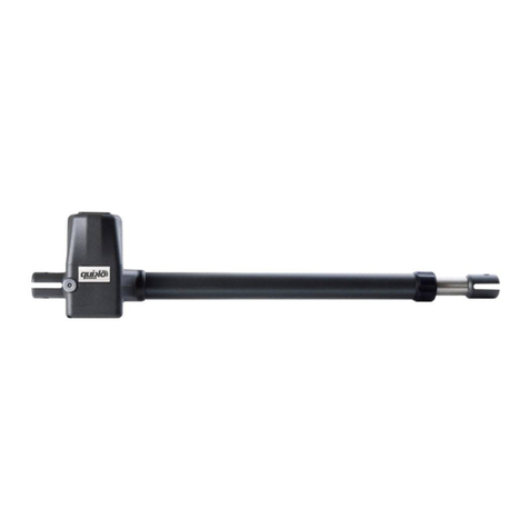
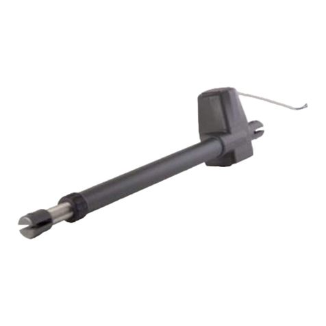
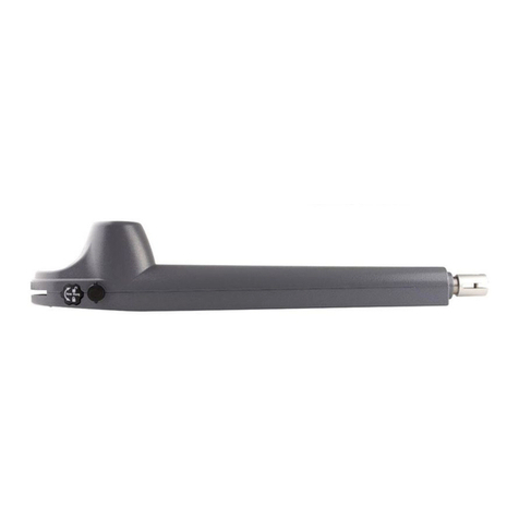
quiko SPIDER QK-S400KIT User manual

E
N
G
L
I
S
H
I
T
A
L
I
A
N
O
ARTICULATED ARM SWING GATE OPENER
AUTOMAZIONE A BRACCIO ARTICOLATO PER CANCELLI A BATTENTE
SPIDER
m
a
n
u
a
l
e
d
’
u
s
o
e
m
a
n
u
t
e
n
z
i
o
n
e
u
s
e
a
n
d
m
a
i
n
t
e
n
a
n
c
e
m
a
n
u
a
l

3
3
3
4
4
5
5
5
6
6
7
7
7
8
9-10
1
Stabilimento 2
Via Seccalegno, 19
36040 Sossano (VI) - Italia
Tel: +39 0444 785513 Fax: +39 0444 782371
Quiko
®
è un marchio:
Borinato F.lli Snc
E-mail: info@quiko.biz
Web: www.quiko.biz
Sede legale e stabilimento 1
Via Chiesa, 59
36040 San Germano D.B. (VI) - Italia
Tel: +39 0444 868126 Fax: +39 0444 868126
CONTENTS
INTRODUCTION 2
MAIN FEATURES OF THE CONTROL BOARD 2
TECHNICALDATA 2
INSTALLATION 2
LAYOUT AND CONNECTIONS 3
OTHERSETTINGS 4
RADIORECEIVER SETUP 4
SETUP 5
FINALTESTING 6
TROUBLESHOOTING 6
DECLARATION OF COMPLIANCE 7
QUIKO
®
GUARANTEE: GENERAL CONDITIONS 8
TECHNICAL FEATURES
PRE-INSTALLATION CONTROL
MATERIALS FOR INSTALLATION
MEASURES TO BE RESPECTED
MEASURES OF THE OPERATOR
USE OF THE CONNECTORS OF THE MOTORS
USE OF THE MANUAL UNLOCKING
ELECTRICAL CONNECTIONS
TYPICAL SYSTEM INSTALLATION
ELECTRICAL CABLES’ CROSS SECTION
GENERAL ADVICE
USE
MAINTENANCE
GUIDE FOR THE INSTALLATION OF HINGED GATES
DECLARATION OF COMPLIANCE

3
E
N
G
L
I
S
H
TECHNICAL FEATURES
QK-S400KIT
QK-S400BKIT
Power supply 230Vac 50Hz 24Vdc
Current absorbed (motor) (A)
1,5
3,5
Power absorbed (W)
340
85
Output speed (r.p.m.) 1,70 1,76
Capacitor
(
F
)
10
-
Protection rate (IP)
Maximum output torque (Nm) 350 400
Opening time (sec)
14
13
Maximum opening angle
(
°
)
Operating temperature (°C Min/Max)
Thermal protection
(
°C
)
140
-
Work Cycle (%)
60
100
Weight of the motor (kg)
Maximum leaf length (m)
Maximum leaf weight (kg)
250
300
3,5
110
-30/+70
44
9,5
PRE-INSTALLATION CONTROL
Before installing the automation, you must check that the gate leaf/leaves:
- can turn without sticking in the ground;
- does not swing during its movement;
- is kept in axis by the special hinges;
- has the stoppers when opening and closing.
Borinato F.lli Snc is liable only for products it manufactures and commercializes. Once
installed, the gate becomes a machine and it is therefore subjected to the rules of the
“Machinery Directive”. It is responsibility of the installer to verify its security. WARNING:
Borinato F.lli Snc is not liable for any damages to people, animals or things due to
unauthorised modifications, alterations or betterments on its products by third parties.
MATERIALS FOR INSTALLATION (For each operator)
1
2
3
4
5
6
7
Ref.
#
Q,TY DESCRIPTION
1 1 STRAIGHT ARM
2 2 BENT ARM
3 1 FRONT BRACKET
4 2 BOLT M14X30
5 2 WASHER ST 14 ISO
7091
6 2 LOCKING NUT M14
7 1 MOTOR BRACKET
8 4 Concrete Anchor Bolts
(not supplied)

4
MEASURES TO BE RESPECTED
Fig. 1
INSTALLATION
1- Provide to fix, temporary, the motor bracket to the pillar until the complete assembly has been
carried out successfully;
2- Brackets must be installed so that the operator, once hinged on them, moves in a horizontal plane;
3- Arrange the installation according to the values of the Fig. 1 and referred table;
4- If different angles have to be referred to then use the following procedure:
4a- temporary fix with two anchor bolts the motor bracket to the pillar centre in such manner that
its edges do not outstand the pillar;
4b- position the motor assembly on the bracket and bolt to it;
4c- install the straight arm, the bent arm and bolt with them;
4d- install the front bracket and bolt to the bent arm;
4e- unlock the rotation of the motor acting on the manual release lock;
4f- move the articulated arm (the angle between the arms must not overcome 178°see Fig. 1)
until the front bracket touch the leaf of the gate in closed position;
4g- tack the position on the leaf;
4h- turn the articulated assembly and the leaf to the maximum open position;
4i- check if the front flange touches the leaf in the previous tacked position;
4l- If the position is different it is needed to shift the anchor point of the motor bracket and repeat
the procedure.
If necessary, it is possible to install the motor internally and let the gate open externally (push to open).
MEASURES OF THE OPERATOR
A (mm) B (mm) C (mm) D (mm)
160 220 794 445
160 370 750 480
160 480 670 540
160 Max 530 640 580

5
E
N
G
L
I
S
H
USE OF THE CONNECTORS OF THE MOTORS
The motors are supplied with a removable connector. (see the label on the above image).
Terminals No 0-1-2-3 are used for the limit switches connection.
Terminals No 4-5-6 are used for the motor power supply.
Adjust the limit switches cammes according to the leaves opening angle.
The limit switches intervention shut off the motor.
USE OF MANUAL UNLOCKING
1- Remove the cap from the cover; 2- Insert the special key(supplied) into the square insert and turn: 2a - 180° counter clockwise for the
operator installed on the right side; 2b - 180° clockwise for the operator installed on the left side.
ELECTRICAL CONNECTIONS
1 – Connect cables with at least 1.5 mm2 section to the control board, checking the motor’s rotation direction and remembering that:
the yellow-green wire = ground / blue wire = common / black wire = phase / brown wire = phase
2 – Connect the provided capacitor in parallel with the motor’s phases.

6
TYPICAL SYSTEM INSTALLATION
MAIN COMPONENTS
Articulated arm operators (2x)
Pair of photocells on the pillars (1x)
Pair of photocells on little columns (1x)
Gate stoppers in the ground (3x)
Key selector (1x)
Flashing lamp with aerial (1x)
Control board and receiver (1x)
ELECTRICAL CABLES CROSS SECTION
Ref. Description Cables section mm
2
1 Main Power supply 3 x 1,5
2 -3 Motor power supply 4 x 1,5 (QK-S400) 2x1,5 (QK-S400B)
4 Transmitting Photocells 2 x 0,5
5 Receiving photocells 4 x 0,5
6 Key selector 3 x 1,5
7 Flashing light 2 x 0,5
8 Aerial RG58

7
E
N
G
L
I
S
H
GENERAL ADVICE
Install a gate’s safety system that complies with current regulations. Choose short routes for cables and keep
power cables separate from control ones. Install the control card in a waterproof box. Please refer to current
regulations when setting the gear motor’s maximum torque. We advice you to install an outdoor switch, in
compliance with European standards on the issue of safety, to turn the electricity off when servicing the gate.
Check that each single installed device is efficient and effective. Affix easily readable signs warning about the
presence of a motorised gate.
USE
It is absolutely forbidden to use the device for any other purposes.
In case of power failure, act on the manual unlocking device and move manually the gate. Remember that this is
an automatic device powered by electricity, consequently use with care. In particular, remember:
- not to touch the device with wet hands and/or wet or bare feet;
- cut off the power before opening the control box and/or actuator;
- not to pull the lead to pull the plug out;
- to put the gate in movement only when it is completely visible;
- to keep out of the gate’s range of action if it is moving. Wait until it has stopped;
- not to let children or animals play near the gate;
- not to let children use the remote control or other operating devices;
- in case of failure, to turn off the switch power and operate the gate manually only if it is possible and safe. Refrain
from touching the gate and call an authorised technician.
MAINTENANCE
Operators need very little maintenance; however their function depends also on the gate conditions, hence here
are operations to be done to keep the gate efficient at all times. Warning: only a skilled technician shall be able to
control the automatic gate while it is being serviced. For this reason please cut off power, avoiding also electric
shocks hazard. If on the contrary power is required for some checks, only authorized technician shall do that
Routine maintenance
Each of the following operations must be done when needed and in all cases at least every 6 months:
1) Mechanical maintenance
Lubricate the hinges on which the gate swings;
check the good conditions of brackets and motor’s hinges;
check the right functioning of the unlocking mechanism
2) Electrical maintenance
Check the proper working of the safety devices;
check the ground connection integrity,
Test, by pushing the proper pushbutton, the efficiency of the differential circuit breaker ( 0,30 mA sensibility)
Try the differential switcher once a month by pushing the special test button on the switcher.


8
A.
Impact
B.
Crushing
C.
Insulation
D. Conveyance E. Cutting F. Slicing
A
B
C
D
E
F
GUIDE FOR THE INSTALLATION OF HINGED GATES
IN ACCORDANCE WITH REGULATION 98/37/CE ON MACHINERY AND WITH REGULATION
EN 12453 – EN 12445
Risk Areas on Hinged Gates (figure 1)
LEGEND OF MECHANICAL RISKS CAUSED BY MOVEMENT
In accordance with the Regulation on Machinery, the following definitions are applicable:
“Danger Zones:” any area inside and/or near a machine where the presence of a person is a risk to his/her
health and safety.
“Exposed Person:” any person located entirely or partially in a danger zone.
MINIMUM LEVEL OF PROTECTION FOR THE MAIN EDGE
Mode of Use
Type of Activation Controls Informed Users
(private area)
Informed Users
(public area) Uninformed Users
Man-operated Command
Button command Turnkey button
command
The man-operated
command is not
allowed
Pulse command with visible
doors
Power limitation
Detectors
Power limitation
Detectors
Power and photo
cell limitation
Detectors
Pulse command with non-
visible doors
Power limitation
Detectors
Power and photo
cell limitation
Detectors
Power and photo
cell limitation
Detectors
Automatic control (e.g.
timed closing control)
Power and photo-
cell limitation
Detectors
Power and photo-
cell limitation
Detectors
Power and photo-
cell limitation
Detectors

10
DECLARATION OF COMPLIANCE
(by the installer)
The undersigned:
Address:
in charge of the set-up, declares that the product:
Gate type:
Location:
are in compliance with the essential safety requirements of the regulations:
Regulation 89/392CE on Machinery and its subsequent amendments;
EMC Regulation 89/336/CE (Legislative Decree 615/96);
BT Regulation 73/23/CE e 93/68/CE (Legislative Decree 626/96);
CE Machinery Directive 98/37 and directive 93/68/CE-72/23/CE-92/31/CE;
and also declares that the related and/or specific national technical regulations have been
followed:
EN 12453/EN 12445 on Industrial, Commercial and Residential Gates and Doors – Safe
Use of Motorized Doors – Requirements and Classification – Test Methods;
EN 12604/ EN 12605 on Industrial, Commercial and Residential Gates and Doors –
Mechanical Aspects – Requirements and Classification – Test Methods;
CEI 64/8 Electrical Systems Using Nominal Tension Not Higher Than 1000V a.c. and
1500 V d.c.;
EN 13241-1 (Industrial, commercial and garage doors and gates), conformity evaluation
(6.3).
Notes:
Place and date: ………………………………… Stamp and Signature

11
E
N
G
L
I
S
H

m
a
n
u
a
l
e
d
’
u
s
o
e
m
a
n
u
t
e
n
z
i
o
n
e

I
T
A
L
I
A
N
O
m
a
n
u
a
l
e
d
’
u
s
o
e
m
a
n
u
t
e
n
z
i
o
n
e
AUTOMAZIONE A BRACCIO ARTICOLATO PER CANCELLI A BATTENTE
SPIDER

INDICE
3
3
3
4
4
5
5
5
6
6
7
7
7
8
9-10
DATI TECNICI
CONTROLLI PRIMA DELLA INSTALLAZIONE
MATERIALI PER L’INSTALLAZIONE
MISURE DA RISPETTARE
MISURE DELL’OPERATORE
USO DEI CONNETTORI DEI MOTORI
USO DELLO SBLOCCO MANUALE
COLLEGAMENTI ELETTRICI AL MOTORE
IMPIANTO TIPO
SEZIONE DEI CAVI DI COLLEGAMENTO
RACCOMANDAZIONI DI CARATTERE GENERALE
USO
MANUTENZIONE
ANALISI DEI RISCHI
DICHIARAZIONE DI CONFORMITà

3
I
T
A
L
I
A
N
O
DATI TECNICI
QK-S400KIT
QK-S400BKIT
Alimentazione 230Vac 50Hz 24Vdc
Assorbimento motore (A)
1,5
3,5
Potenza assorbita (W) 340 85
Velocità albero d'uscita (r.p.m.) 1,70 1,76
Condensatore (F)
10
-
Grado di protezione (IP)
Potenza massima (Nm)
350
400
Tempo di apertura (sec) 14 13
Massimo angolo di apertura (°)
Temp. di esercizio (°C Min/Max)
Termoprotezione (°C) 140 -
Ciclo di lavoro (%)
60
100
Peso del motore (kg)
Lunghezza max. anta (m)
Peso max. anta (kg)
250
300
3,5
110
-30/+70
44
9,5
CONTROLLI PRIMA DELLA INSTALLAZIONE
Prima di procedere all’installazione dell’automazione occorre verificare che l’anta del cancello:
- Possa ruotare senza impedimenti nel terreno;
- Non oscilli durante la rotazione;
- Sia tenuta in asse vericale dalle apposite cerniere;
- Sia dotata di arresti in apertura e chiusura;
Si ricorda che Borinato F.lli Snc è responsabile solo degli articoli che produce e commercializza. II
cancello, una volta automatizzato, diventa un macchinario ed è quindi soggetto alle norme della
Direttiva Macchine. E' quindi compito dell'installatore verificarne la sicurezza. ATTENZIONE:
Borinato F.lli Snc non risponde di eventuali danni a persone, animali o cose derivanti da modifiche,
alterazioni o migliorie apportate arbitrariamente da terzi ai suoi prodotti
MATERIALI PER L’INSTALLAZIONE (Per ogni operatore)
1
2
3
4
5
6
7
Rif
# Q,TA’ DESCRIZIONE
1 1 BRACCIO DIRITTO
2 2 BRACCIO CURVO
3 1 STAFFA ANTERIORE
4 2 BULLONE M14X30
5 2 RONDELLA ST 14 ISO 7091
6 2 DADO AUTOBLOCCANTE M14
7 1 STAFFA SUPPORTO
OPERATORE
8 4 Tasselli di ancoraggio (non
forniti)

4
MISURE DA RISPETTARE
Fig. 1
INSTALLAZIONE
FISSARE PROVVISORIAMENTE LA STAFFA SUPPORTO OPERATORE AL PILASTRO FINCHÈ NON SI
SONO COMPLETATE POSITIVAMENTE I PUNTI DA 1 A 8 ELENCATI QUI DI SEGUITO.
La staffa deve essere posizionata in bolla in maniera che la rotazione dei bracci avvenga in un piano
orizzontale.
Sistemare l’operatore tenendo in considerazione le dimensioni riportate nella figura 1
Se non è possibile rispettare le dimensioni indicate si proceda come segue.
1. fissare temporaneamente la staffa con due tasselli al pilastro nella posizione desiderata
2. posizionare l’operatore sulla staffa e fissarlo con le apposite viti
3. assemblare I bracci tra loro e all’albero scanalato del motore
4. montare la staffa anteriore sul braccio curvo
5. sbloccare la rotazione del motore ruotando l’alberino di sblocco con la chiave ad inserto quadro
6. ruotare I bracci in maniera che formino tra loro un angolo acuto o al massimo di 178°
7. accostare la staffa anteriore all’anta e marcare la posizione
8. tenendo bloccata la posizione relativa dei due bracci ruotare l’anta e i bracci fino alla posizione di
max. apertura
9. controllare se la flangia si appoggia all’anta nella posizione marcata.
Se la posizione coincide si può procedere con il fissaggio definitivo altrimenti occorre spostare la posizione
di ancoraggio della staffa e ripetere la procedura dal punto 6
SE RICHIESTO L’OPERATORE PUÒ ESSERE INSTALLATO IN MANIERA DA APRIRE IL CANCELLO
VERSO L’ESTERNO
MISURE DELL’OPERATORE
A (mm) B (mm) C (mm) D (mm)
160 220 794 445
160 370 750 480
160 480 670 540
160 Max 530 640 580

5
I
T
A
L
I
A
N
O
MISURE DA RISPETTARE
Fig. 1
INSTALLAZIONE
FISSARE PROVVISORIAMENTE LA STAFFA SUPPORTO OPERATORE AL PILASTRO FINCHÈ NON SI
SONO COMPLETATE POSITIVAMENTE I PUNTI DA 1 A 8 ELENCATI QUI DI SEGUITO.
La staffa deve essere posizionata in bolla in maniera che la rotazione dei bracci avvenga in un piano
orizzontale.
Sistemare l’operatore tenendo in considerazione le dimensioni riportate nella figura 1
Se non è possibile rispettare le dimensioni indicate si proceda come segue.
1. fissare temporaneamente la staffa con due tasselli al pilastro nella posizione desiderata
2. posizionare l’operatore sulla staffa e fissarlo con le apposite viti
3. assemblare I bracci tra loro e all’albero scanalato del motore
4. montare la staffa anteriore sul braccio curvo
5. sbloccare la rotazione del motore ruotando l’alberino di sblocco con la chiave ad inserto quadro
6. ruotare I bracci in maniera che formino tra loro un angolo acuto o al massimo di 178°
7. accostare la staffa anteriore all’anta e marcare la posizione
8. tenendo bloccata la posizione relativa dei due bracci ruotare l’anta e i bracci fino alla posizione di
max. apertura
9. controllare se la flangia si appoggia all’anta nella posizione marcata.
Se la posizione coincide si può procedere con il fissaggio definitivo altrimenti occorre spostare la posizione
di ancoraggio della staffa e ripetere la procedura dal punto 6
SE RICHIESTO L’OPERATORE PUÒ ESSERE INSTALLATO IN MANIERA DA APRIRE IL CANCELLO
VERSO L’ESTERNO
MISURE DELL’OPERATORE
A (mm) B (mm) C (mm) D (mm)
160 220 794 445
160 370 750 480
160 480 670 540
160 Max 530 640 580
USO DEI CONNETTORI DEI MOTORI
La morsettiera rimovibile comprende alcuni morsetti.
I morsetti N. 0-1-2-3 servono per collegare I finecorsa.
I morsetti N. 4-5-6 servono per il collegamento del motore (vedere la targhetta applicata)
Regolare le camme finecorsa in accordo con l’angolo di apertura prefissato delle ante. L’intervento del finecorsa interrompe
l’alimentazione del motore.
USO DELLO SBLOCCO MANUALE
Per le manovre di emergenza in caso di black-out occorre: togliere il tappo di chiusura posto sul coperchio, inserire la chiave ad
innesto quadro (fornita) sul perno di sblocco e ruotare lo stesso in senso antiorario di 180°, se l’operatore è destro o in senso orario di
180°, se l’operatore è sinistro
COLLEGAMENTI ELETTRICI AL MOTORE
Eseguire le connessioni con un cavo da 4x1,5 mm2 tenendo presente le seguenti colorazioni: Giallo/verde = massa; blu =
comune; nero = fase; marrone = fase. Collegare un condensatore da 10 F. Controllare la corretta rotazione del motore e se
necessario invertire le fasi del motore.

6
IMPIANTO TIPO
PRINCIPALI COMPONENTI
Due operatori a braccio articolato
Due fotocellule fissate ai pilastri
Due fotocellule su colonnine
Tre arresti per ante
Un selettore a chiave
Un lampeggiante
Un quadro di comando
Una antenna
SEZIONE DEI CAVI DI COLLEGAMENTO
Rif. Descrizione Sezione del cavo (mm2)
1 Alimentazione al quadro 3 x 1,5
2 -3 Alimentazione motori 4 x 1,5 (QK-S400) 2x1,5 (QK-
S400B)
4 Fotocellule trasmittenti 2 x 0,5
5 Fotocellule riceventi 4 x 0,5
6 Selettore a chiave 3 x 15
7 lampeggiante 2 x 0,5
8 Antenna RG58

7
I
T
A
L
I
A
N
O
RACCOMANDAZIONI DI CARATTERE GENERALE
Integrare la sicurezza del cancello conformemente alla normativa vigente. Scegliere percorsi brevi per i cavi e tenere
separati i cavi di potenza dai cavi di comando. Installare la scheda di comando in una scatola a tenuta stagna. Per la
messa a punto della coppia massima dell’operatore, attenersi alle normative in vigore. In accordo con la normativa
europea in materia di sicurezza si consiglia di inserire un interruttore esterno per poter togliere l’alimentazione in caso di
manutenzione del cancello. Verificare che ogni singolo dispositivo installato sia efficiente ed efficace. Affiggere cartelli
facilmente leggibili che informino della presenza del cancello motorizzato.
USO
Si fa espresso divieto di utilizzare l'apparecchio per scopi diversi.
In caso di mancanza di energia elettrica, agire sul dispositivo di sblocco manuale e muovere il cancello manualmente.
Si ricorda che siamo in presenza di un dispositivo automatico e alimentato a corrente, perciò da usare con precauzione.
In particolare, si esorta a:
non toccare l'apparecchio con mani bagnate e/o piedi bagnati o nudi;
togliere la corrente prima di aprire la scatola comandi e/o l’operatore
non tirare il cavo di alimentazione per staccare la presa di corrente;
mettere in movimento il cancello solo quando è completamente visibile;
tenersi fuori dal raggio di azione del cancello se questo è in movimento: aspettare fino a che non sia fermo;
non lasciare che bambini o animali giochino in prossimità del cancello;
non lasciare che bambini usino il telecomando o altri dispositivi di azionamento;
eseguire una manutenzione periodica;
in caso di guasto, togliere l'alimentazione e gestire il cancello manualmente solo se possibile e sicuro. Astenersi da ogni
intervento e chiamare un tecnico autorizzato.
MANUTENZIONE
Gli operatori necessitano di poca manutenzione; tuttavia il loro buon funzionamento dipende anche dallo stato del
cancello, perciò descriveremo brevemente anche le operazioni da fare per avere un cancello sempre efficiente.
Attenzione: nessuna persona ad eccezione del manutentore, che deve essere un tecnico specializzato, deve poter
comandare il cancello automatico durante la manutenzione. Si raccomanda perciò di togliere l'alimentazione di rete,
evitando così anche il pericolo di shock elettrici. Se invece l'alimentazione deve essere presente per talune verifiche, si
raccomanda di controllare o disabilitare ogni dispositivo di comando (telecomandi, pulsantiere, ecc.) ad eccezione del
dispositivo usato dal manutentore.
Manutenzione ordinaria
Ciascuna delle seguenti operazioni deve essere eseguita quando se ne avverte la necessità e comunque ogni 6 mesi:
Manutenzione meccanica
Lubrificare (con oliatore) i cardini su cui il cancello gira;
controllare il buono stato delle staffe e i perni del motore;
eseguire una manovra di sblocco per assicurarsi che il meccanismo sia sempre efficiente.
Manutenzione elettrica
Controllare il buono stato dei dispositivi di sicurezza;
controllare l’efficacia del trimmer di regolazione della spinta
controllare l’efficacia dell’impianto di terra (differenziale). Provare l’interruttore differenziale una volta al mese premendo
l’apposito pulsante di test sull’interruttore.
IMPIANTO TIPO
PRINCIPALI COMPONENTI
Due operatori a braccio articolato
Due fotocellule fissate ai pilastri
Due fotocellule su colonnine
Tre arresti per ante
Un selettore a chiave
Un lampeggiante
Un quadro di comando
Una antenna
SEZIONE DEI CAVI DI COLLEGAMENTO
Rif. Descrizione Sezione del cavo (mm2)
1 Alimentazione al quadro 3 x 1,5
2 -3 Alimentazione motori 4 x 1,5 (QK-S400) 2x1,5 (QK-
S400B)
4 Fotocellule trasmittenti 2 x 0,5
5 Fotocellule riceventi 4 x 0,5
6 Selettore a chiave 3 x 15
7 lampeggiante 2 x 0,5
8 Antenna RG58

8
A. Impatto B. Schiacciamento C. Cesoiamento
D. Convogliamento E. Taglio F. Uncinamento
A
B
C
D
E
F
ANALISI DEI RISCHI
Qui di seguito si elencano i rischi meccanici connessi all’utilizzo dei cancelli a battente automatizzati. Per
una più approfondita analisi degli stessi e delle prescrizioni richieste dalle normative si rimanda alla GUIDA
UNAC N. 2 PER LA AUTOMAZIONE DEI CANCELLI A BATTENTE IN CONFORMITÀ ALLA DIRETTIVA
MACCHINE 98/37/CE E ALLE PARTI APPLICABILI DELLE NORME EN 13241-1, EN 12453, EN 12445
Fig 2
Zone di rischio del cancello a battente (figura 2).
LEGENDA DEI RISCHI MECCANICI DOVUTI AL MOVIMENTO
Ai sensi della Direttiva Macchine, si intende per:
“Zone pericolose”, qualsiasi zona all’interno e/o in prossimità di una macchina in cui la presenza di una
persona esposta costituisca un rischio per la sicurezza e la salute di detta persona.
“Persona esposta”, qualsiasi persona che si trovi interamente o in parte in una zona pericolosa.

10
DICHIARAZIONE DI CONFORMITA’
(da parte dell’installatore)
Il sottoscritto:
________________________________________________________________
Indirizzo:
________________________________________________________________
in qualità di responsabile della messa in funzione dichiara che il prodotto:
Tipologia
________________________________________________________________
Ubicazione:
________________________________________________________________
è conforme ai requisiti essenziali di sicurezza delle direttive:
Direttiva Macchine 89/392CE e successive modificazioni;
Direttiva EMC 89/336/CE (D.Lgs 615/96);
Direttiva BT 73/23/CE e 93/68/CE (D. Lgs 626/96);
Direttiva Macchine 98/37 CE e direttive 93/68/CE-72/23/CE-92/31/CE;
inoltre dichiara che sono state applicate le norme armonizzate e/o le norme
specifiche tecniche nazionali:
EN 12453/EN 12445 Cancelli e porte industriali commerciali e residenziali –
Sicurezza nell’uso delle porte motorizzate – Requisiti e classificazione – Metodi di
prova;
EN 12604/ EN 12605 Cancelli e porte industriali commerciali e residenziali –
Aspetti meccanici – Requisiti e classificazione – Metodi di prova;
CEI 64/8 Impianti elettrici utilizzatori a tensione nominale non superiore a 1000V
c.a. e 1500 V c.c.;
EN 13241-1 (Porte e cancelli industriali, commerciali e da garage), valutazione di
conformità (6.3).
Luogo e data: ________________________ Timbro e firma
This manual suits for next models
1
Table of contents
Languages:
Other quiko Gate Opener manuals

quiko
quiko QK-H300 Guide

quiko
quiko HYDRO H300BAC User manual

quiko
quiko QK-S400 User manual

quiko
quiko Rotello QK-R300 User manual

quiko
quiko Titano QK-T4000 User manual

quiko
quiko SCARABEO Series User manual

quiko
quiko SCARABEO QK-SCA230 User manual

quiko
quiko NEO Series User manual

quiko
quiko NEO QK-N400 User manual

quiko
quiko Zebra Series User manual