Version 06.09.2018 HW (V32)/CY10(V41) CI-RL5-UCON8-CP
Contents
1. Prior to installation
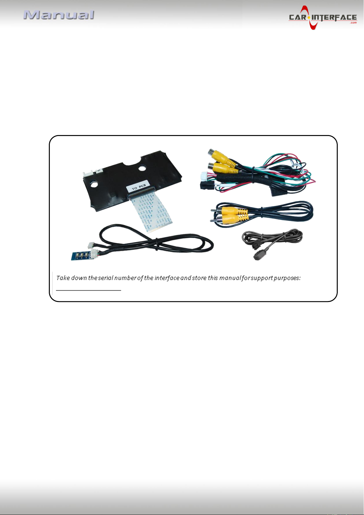
1.1. Delivery contents
1.2. Checking the interface compatibility of vehicle and accessories
1.3. Connectors –video interface (daughter PCB)
2. Installation
2.1. Place of installation
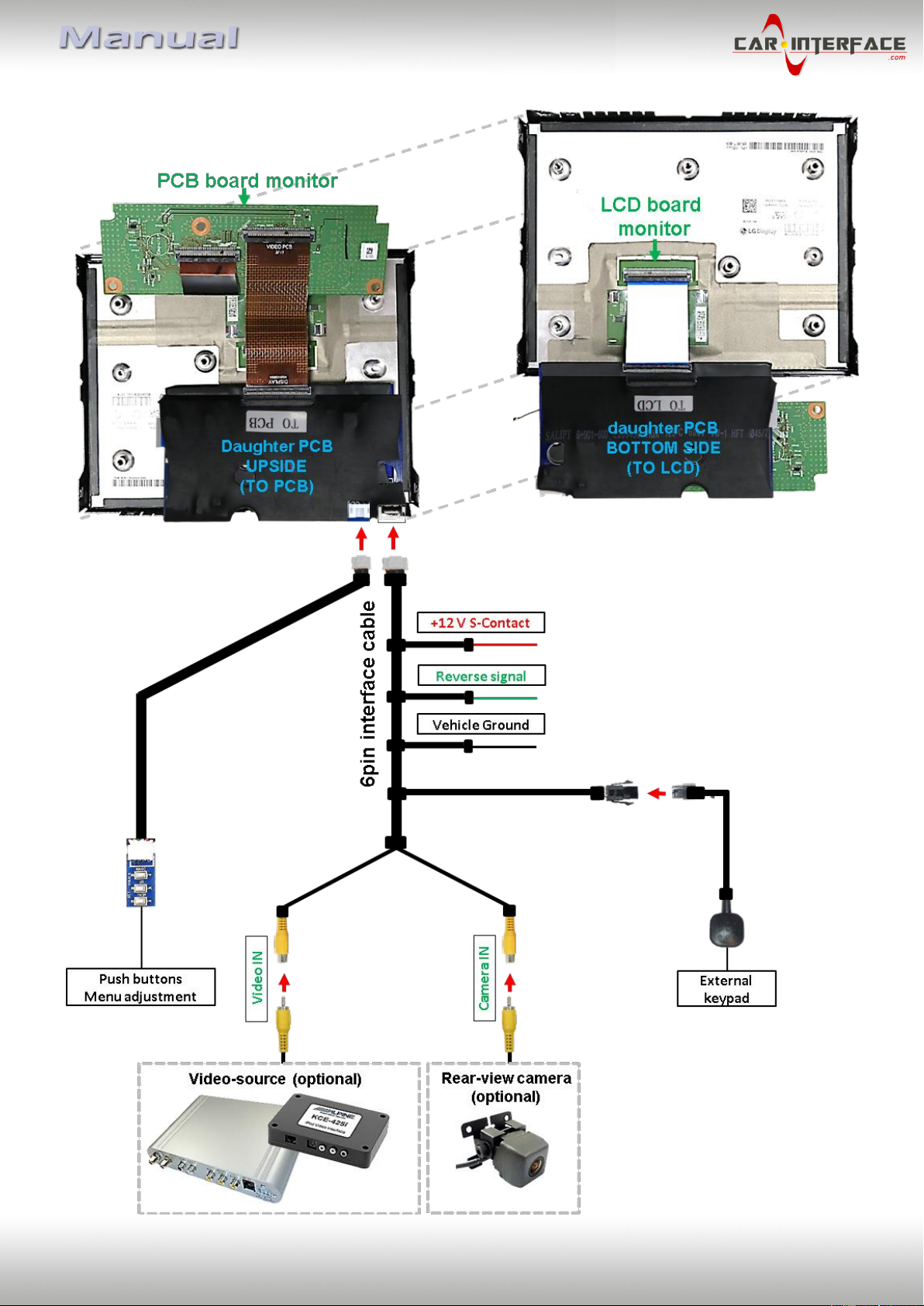
2.2. Connection scheme
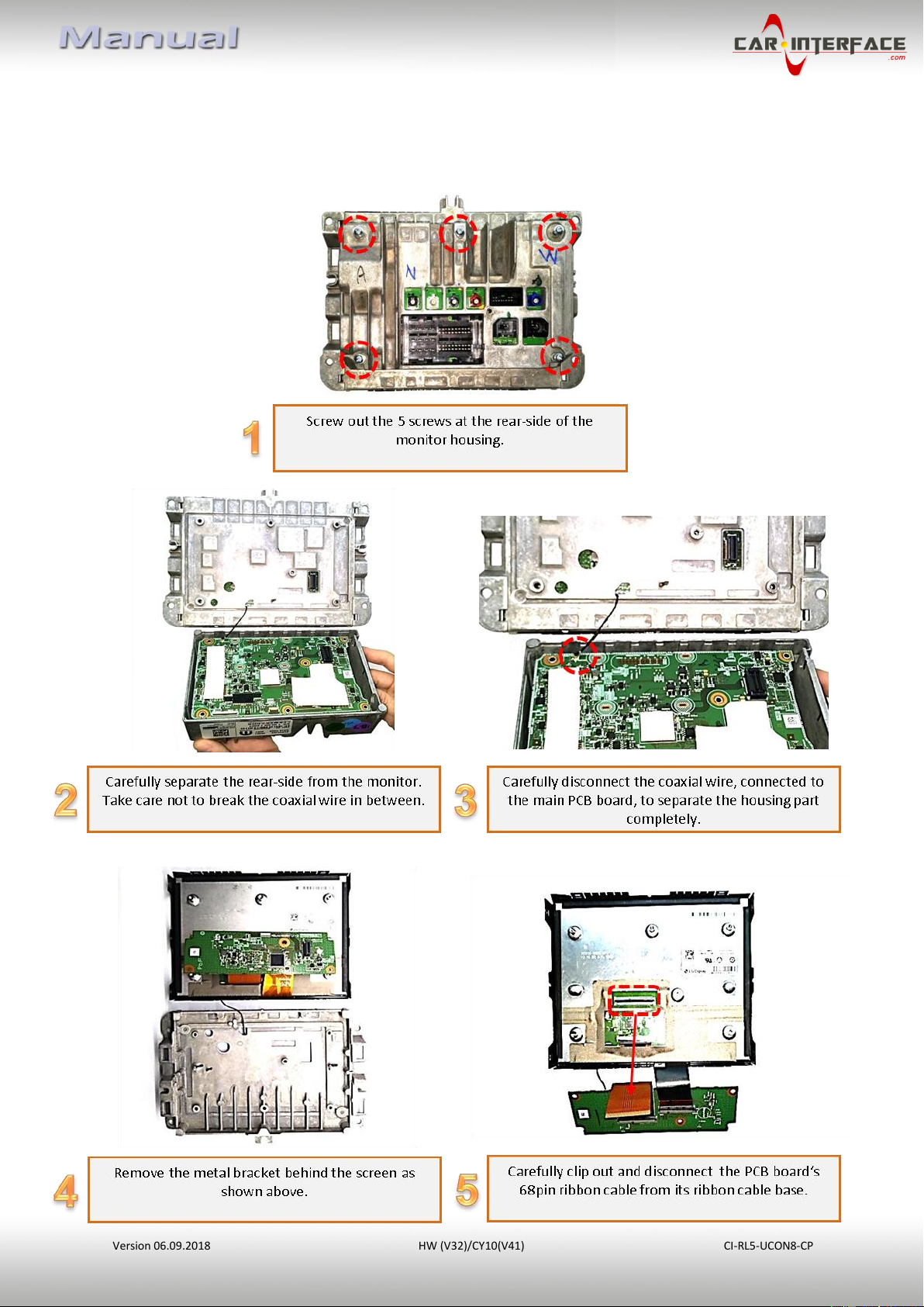
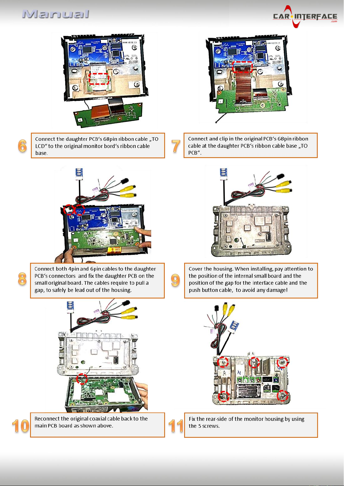
2.3. Installation - Ribbon cables into the monitor panel
2.3.1. Warning notes, concerning the installation of ribbon cables
2.4. Cable connections –daughter PCB
2.5. After-market rear-view camera:
2.6. Connection –video inputs
2.7. Connection - keypad
3. Interface operation by external keypad
4. Picture settings
5. Specifications
6. Frequently asked questions
7. Technical support
Legal Information
By law, watching moving pictures while driving is prohibited, the driver must not be
distracted. We do not accept any liability for material damage or personal injury resulting,
directly or indirectly, from installation or operation of this product. This product should only
be used while standing or to display fixed menus or rear-view-camera video when the
vehicle is moving, for example the MP3 menu for DVD upgrades.
Changes/updates of the vehicle’s software can cause malfunctions of the interface. We
offer free software-updates for our interfaces for one year after purchase. To receive a free
update, the interface must be sent in at own cost. Labour cost for and other expenses
involved with the software-updates will not be refunded.