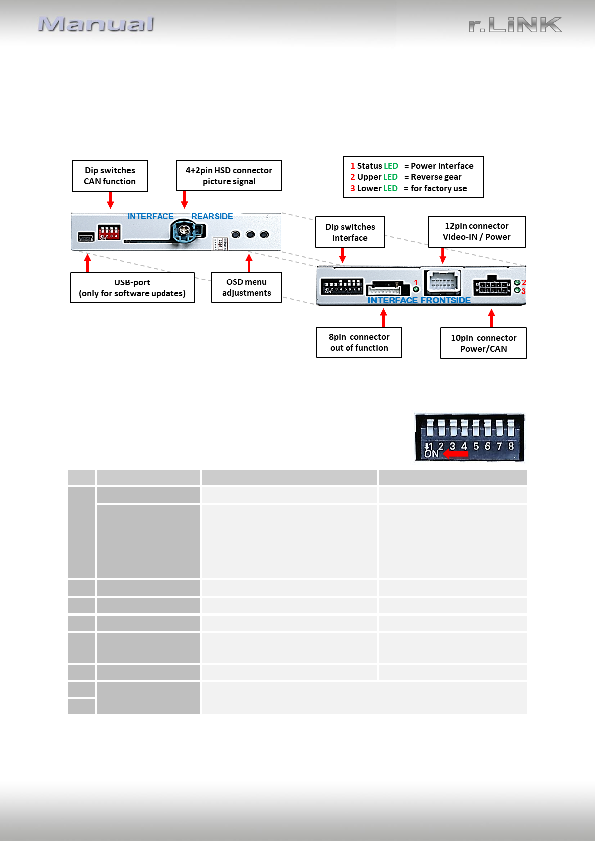
Version 18.03.2020 HW CAM(V98)/(V52) RL4-MBN51
1.4.1. Activating the front camera (dip 1)
If set to ON, the interface switches for 10 seconds from the rear-view camera to the front
camera input after having disengaged the reverse gear. In addition, a manual switch-over to
the front camera input is possible via keypad (short press) from any image mode.
1.4.2. Enabling the interface’s video inputs (dip 2-3)
Only the enabled video inputs can be accessed when switching through the interface’s video
sources. It`s recommended to enable only the required inputs, for the disabled will be
skipped when switching through the video interfaces inputs.
1.4.3. Rear-view camera setting (dip 5)
If set to OFF, the interface switches to factory LVDS picture while the reverse gear is engaged
to display a factory rear-view camera or a factory optical park system picture.
If set to ON, the interface switches to its rear-view camera input “Camera-IN” while the
reverse gear is engaged.
Note: Dips 4and 6 are out of function and have to be set to OFF.
1.4.4. Monitor selection (dips 7-8)
Dips 6-8 are for monitor-specific video settings which cannot be predicted as even within the
same head-unit version, the monitor specifications may vary. It is necessary to try all
possible combinations - while a working video source is connected to the chosen input of the
interface - to see which combination gives the best picture quality and size (some may give
no picture). It is possible to first hot plug through the dip combinations, but if you do not
experience any change of picture after trying all options, retry and disconnected the 10pin
power plug of the video-box between every change of the dip setting.
After each Dip-switch-change a power-reset of the Interface-box has to be performed!
1.5. Settings of the 4 Dip switches (CAN functions –red)
Dip position UP = OFF and DOWN = ON.
Vehicles with NTG5 (-205)*
Warning: If dip switch 3 has not been set to the vehicle specific correct position, CAN-bus
faults may occur, which extremely disturb the vehicle’s instrument electronics!
*Vehicle specific infotainment assignments can be taken from the yellow box on page 4!