r.LiNK RL3-SY3 User manual

Version 08.02.2019 CAM(V98)/(V50+V41) RL3-SY3
r.LiNK Video-inserter
RL3-SY3
Compatible with Ford vehicles with
Sony Sync3 Touch with 7 or 8inch monitor
Video-inserter for rear-view camera
and two additional video sources
Product features
Video-inserter for factory-infotainment systems
2 CVBS video-inputs for after-market devices (e.g. USB-Player, DVB-T2 tuner)
CVBS Rear-view camera video-input
Automatic switching to rear-view camera input on engagement of the reverse gear
Activatable parking guide lines for rear-view camera (not available for all vehicles)
Video-in-motion (ONLY for connected video-sources)
Video-inputs NTSC and PAL compatible

Version 08.02.2019 CAM(V98)/(V50+V41) RL3-SY3
Page2
Contents
1. Prior to installation
1.1. Delivery contents
1.2. Checking the compatibility of vehicle and accessories
1.3. Connectors –video interface
1.3.1. Dip switch settings
1.3.1.1. 8 dip - black
1.3.1.2. Enabling the interface’s video inputs (dip 2-3)
1.3.1.3. Rear-view camera setting (dip 5)
1.3.1.4. 4 dip - red
2. Installation
2.1. Place of installation
2.2. Connection schema
2.3. Connecting picture signal cable
2.3.1. ALL-IN-ONE head unit
2.3.2. Separate head unit with tablet monitor
2.4. Connection –PNP Power / CAN cable
2.4.1. ALL-IN-ONE head unit
2.4.2. Separate head unit with tablet monitor
2.5. Analog power supply
3. Connection –video sources
3.1. After-market rear-view camera
3.1.1. Case 1: Interface receives the reverse gear signal
3.1.2. Case 2: Interface does not receive the reverse gear signal
3.2. Connecting video-interface and keypad
3.3. Picture settings
4. Interface operation
4.1. By infotainment button
4.2. By keypad
5. Specifications
6. FAQ –Trouble Shooting-Interface functions
7. Technical support

Version 08.02.2019 CAM(V98)/(V50+V41) RL3-SY3
Page3
Legal Information
By law, watching moving pictures while driving is prohibited, the driver must not be
distracted. We do not accept any liability for material damage or personal injury resulting,
directly or indirectly, from installation or operation of this product. Apart from using this
product in an unmoved vehicle, it should only be used to display fixed menus or rear-view-
camera video when the vehicle is moving (for example the MP3 menu for DVD upgrades).
Changes/updates of the vehicle’s software can cause malfunctions of the interface. Up to
one year after purchase we offer free software-updates for our interfaces. To receive a free
update, the interface has to be sent in at own cost. Wages for de-and reinstallation and
other expenditures involved with the software-updates will not be refunded.
1. Prior to installation
Please read the manual thoroughly BEFORE starting the installation. Technical knowledge is
imperatively required. The place of installation has to be free of moisture and away from
heat sources.
1.1. Delivery contents
Take down the serial number of the interface and store this manual for support
purposes: ____________________

Version 08.02.2019 CAM(V98)/(V50+V41) RL3-SY3
Page4
Compatibility
brand
Compatible vehicles
infotainment systems
Ford
Ford Galaxy from model year 2016
Ford Ranger from model year 2017
Ford S-Max from model year 2016
and other vehicles with
Sony Sync3 Touch –7” or 8”
monitor. Without and with
navigation.
Limitations
Video only The interface inserts ONLY video signals into the infotainment.
For inserting Audio signals either the possibly existing factory audio-
AUX-input or a FM-modulator can be used.
In case that 2 AV sources shall be connected, a desired audio
switching will require additional electronic.
Factory rear-view camera Automatically switching-back from inserted video to factory rear-
view camera is only possible while the reverse gear is engaged. To
delay the switch-back an additional electronic part is required.
Guidelines The display of the guidelines does not work in all vehicles.
1.2. Checking the compatibility of vehicle and accessories
1.3. Connectors –video interface
The video-interface converts the video signals of connected after-market sources in a factory
monitor compatible picture signal which is inserted in the factory monitor, by using separate
trigger options. Further it reads the vehicle’s digital signals out of the vehicle’s CAN-bus and
converts them for the video interface.

Version 08.02.2019 CAM(V98)/(V50+V41) RL3-SY3
Page5
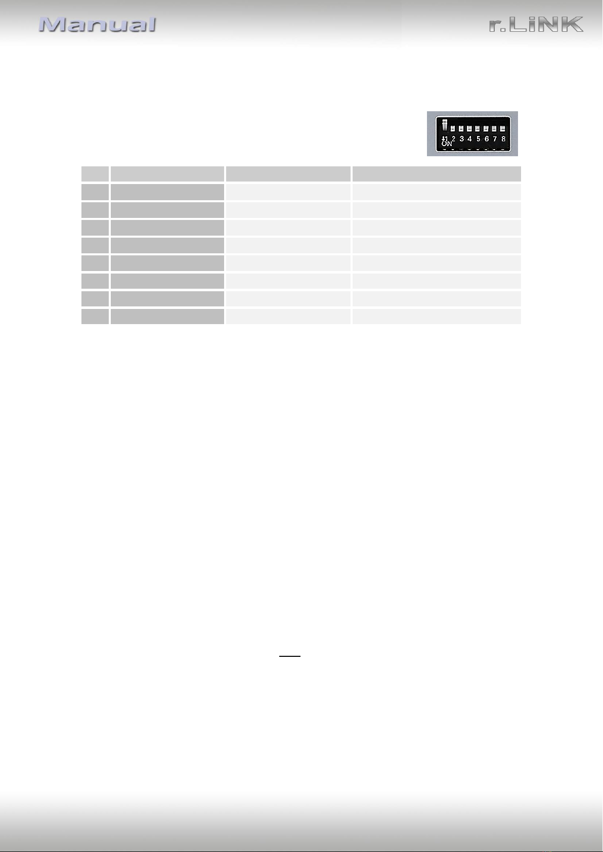
1.3.1. Dip-switch settings
1.3.1.1. 8 dip - black
Some settings have to be selected by the dip-switches on the
video interface.
Dip position down is ON and position up is OFF.
See the following chapters for detailed information.
1.3.1.2. Enabling the interface’s video inputs (dip 2-3)
Only the enabled video inputs can be accessed when switching through the interface’s video
sources. It is recommended to enable only the required inputs, disabled inputs
will be skipped when switching through the video-interfaces inputs.
1.3.1.3. Rear-view camera setting (dip 5)
If set to OFF, the interface switches to factory picture while the reverse gear is engaged to
display factory rear-view camera.
If set to ON, the interface switches to its rear-view camera input „Camera-IN“ while the
reverse gear is engaged.
1.3.1.4. Enabling the Guide lines (dip 7)
If set to ON, the interface is activated to show the guide lines for the rear-view camera while
the vehicle is in reverse mode (not available for all vehicles).
Note: Some vehicles have a different code on the CAN-bus which the video-interface is not
compatible with. If the interface does not fully communicate with the vehicle CAN bus, the
reverse gear guide-lines can`t be shown during the vehicle’s operation, even if they in some
vehicles once appear after having switched the system to powerless!
Note: Dip 1, 4, 6 and 8 are out of function and have to be set to OFF.
Dip
Function
ON (down)
OFF (up)
1
No function
Set to OFF
2
CVBS AV1-input
enabled
disabled
3
CVBS AV2-input
enabled
disabled
4
No function
Set to OFF
5
Rear-view cam type
after-market
factory or none
6
No function
Set to OFF
7
Guide lines
enabled
disabled
8
No function
Set to OFF

Version 08.02.2019 CAM(V98)/(V50+V41) RL3-SY3
Page6
1.3.1.5. 4 dip - red
By using the Dip-switches, the factory Head-unit or vehicle can be chosen
which the interface will be connected to.
Dip position down is ON and position up is OFF.
Vehicle/Navigation
Dip 1
Dip 2
Dip 3
Dip 4
All vehicles
OFF
OFF
OFF
OFF
After each Dip-switch-change a power-reset of the Video Interface has to be performed!
2. Installation
To install the interface, first switch off the ignition and disconnect the vehicle’s battery.
Please read the owner`s manual of the car, regarding the battery`s disconnection! If
required, enable the car`s Sleep-mode (hibernation mode)
In case the sleep-mode does not succeed, the disconnection of the battery can be done
with a resistor lead.
If the necessary stabilized power supply for the interface is not taken directly from the
battery, the chosen connection has to be checked for being constantly stabile.
The interface needs a permanent 12V source!
2.1. Place of installation
The interface is built to be connected behind the vehicle`s head unit.

Version 08.02.2019 CAM(V98)/(V50+V41) RL3-SY3
Page7
2.2. Connection schema

Version 08.02.2019 CAM(V98)/(V50+V41) RL3-SY3
Page8
2.3. Connection –picture signal cable
2.3.1. ALL-IN-ONE head unit
Connect the female picture signal cable’s WATERBLUE coloured HSD+2 connector to
the male WATERBLUE coloured HSD+2 connector of the video interface.
Disconnect the CURRY coloured female 4pin HSD connector of the HSD bridge at the
rear side of the monitor and connect it to the male WATERBLUE coloured HSD
connector of the enclosed 4pin HSD LVDS cable. Caution: The female blue coloured
HSD connector of the HSD bridge must never be disconnected from the monitor’s
rear side!
Connect the female WATERBLUE coloured HSD connector of the enclosed 4pin HSD
picture signal cable to the previously become free male CURRY coloured HSD
connector at the monitor’s rear side.
Caution: The BLUE female HSD connection at the monitor HSD bridge has to remain
connected in the monitor’s rear side during the hole process and must never be
disconnected from its original place.
The picture signal cable has to be connected to the monitor. Connection to the head unit
may cause damage to the system!
Note: No liability for vehicle wire colours and pin definition!
Changes by the vehicle manufacturer are possible. The given information has to be verified
by the installer.

Version 08.02.2019 CAM(V98)/(V50+V41) RL3-SY3
Page9
2.3.2. Separate head unit with tablet monitor
Connect the female picture signal cable’s WATERBLUE coloured HSD+2 connector to
the male WATERBLUE coloured HSD+2 connector of the video interface.
Disconnect the CURRY coloured female 4pin HSD connector of the factory harness at
the rear side of the monitor and connect it to the male WATERBLUE coloured HSD
connector of the enclosed 4pin HSD LVDS cable.
Connect the female WATERBLUE coloured HSD connector of the enclosed 4pin HSD
picture signal cable to the previously become free male CURRY coloured HSD
connector at the monitor’s rear side.
Caution: The picture signal cable has to be connected to the monitor. Connection to the
head unit may cause damage to the system!
Note: No liability for vehicle wire colours and pin definition!
Changes by the vehicle manufacturer are possible. The given information has to be verified
by the installer.

Version 08.02.2019 CAM(V98)/(V50+V41) RL3-SY3
Page10
2.4. Connection –PNP Power / CAN cable
2.4.1. ALL-IN-ONE head unit
Connect the enclosed PNP Power / CAN cable’s female10pin connector to the male
10pin connector of the video interface.
Disconnect the female 54pin connector of the vehicle harness at the rear side of the
monitor and connect it to the male 54pin connector of the enclosed PNP Power/CAN
cable.
Connect the enclosed PNP Power / CAN cable’s opposite female54pin connector to
the previously become free male 54pin connector of the monitor.

Version 08.02.2019 CAM(V98)/(V50+V41) RL3-SY3
Page11
2.4.2. Separate head unit with tablet monitor
To connect the tablet style infotainment (monitor and head unit separated), the
PNP Power / CAN cable’s 4 single wires have to be cut near the big 54pin harness. The 54pin
connection can`t be used!
Connect the single grey wire „CAN LOW“ of the 4 cables to the head unit main connector’s
white/green cable (bottom/right side) and isolate the connection.
Connect the single blue wire „CAN HIGH“ of the 4 cables to the head unit main connector’s
green/blue cable (right beside) and isolate the connection.
Connect the single red wire to stabile +12V terminal 30.
Connect the single brown cable to the vehicle’s Ground.
Note: No liability for vehicle wire colours and pin definition!
Changes by the vehicle manufacturer are possible. The given information has to be verified
by the installer.

Version 08.02.2019 CAM(V98)/(V50+V41) RL3-SY3
Page12
2.5. Analog power supply
Connect the female 12pin connector of the 12pin interface cable to the male 12pin
connector of the video interface.
Connect the 12pin interface cable’s red coloured wire ACC-out (max 3A) and the
purple coloured wire Manual ACC both to S-contact terminal 86s +12V
(e.g. glove compartment illumination).

Version 08.02.2019 CAM(V98)/(V50+V41) RL3-SY3
Page13
3. Connecting Video sources
It is possible to connect one after-market rear-view camera and two after-market AV-
sources to the video-interface.
Before the final installation, we recommend a test-run to detect a incompatibility of
vehicle and interface. Due to changes in the production of the vehicle manufacturer
there’s always a possibility of incompatibility.
Connect the female 12pin connector of the 12pin interface cable to male 12pin
connector of the video-interface.
Connect the video RCA connector of the rear-view camera to the female RCA
connector “Camera-IN” of the 12pin interface cable.
Connect the video RCA connectors of additional video sources to the 12pin interface
cable’s female RCA connectors „Video IN 1” und “Video IN 2”.

Version 08.02.2019 CAM(V98)/(V50+V41) RL3-SY3
Page14
3.1. After-market rear-view camera
Some vehicles have a different reverse gear code on the CAN-bus which doesn’t
communicate with the interface’s CAN. In this case there are two different ways of
installation. If the interface’s CAN is able to detect an enabled vehicle’s reverse gear, the
green wire of the 6pin to 12pin cable should carry +12V while the reverse gear is engaged.
Note: Do not forget to set dip5 of video-interface to ON before testing.
3.1.1. Case 1: Interface receives the reverse gear signal
If the interface receives +12V on the green wire of the 12pin interface cable while reverse
gear is engaged, the video interface will automatically switch to the rear-view camera input
“CAMERA-IN” while the reverse gear is engaged.
The 12 V power supply for the rear-view camera (max 3A) has to be taken from the
12pin interface cabl’s green wire “Reverse-OUT” to avoid an unnecessary,
permanent power supply to the camera electronic.
Both green cables “Reverse IN” and “Reverse OUT” have to remain connected.

Version 08.02.2019 CAM(V98)/(V50+V41) RL3-SY3
Page15
3.1.2. Case 2: Interface does not receive the reverse gear signal
If the video interface does not receive +12V on the green wire of the 12pin interface cable
when reverse gear is engaged (not all vehicles are compatible), an external switching signal
from the reverse gear light is required. As the reverse gear light’s power supply isn’t voltage-
stable all the time, an ordinary open relay (e.g AC-RW-1230 with wiring AC-RS5) or filter (e.g.
AC-PNF-RVC) is required. The diagram below shows the connection type of the relay.
Disconnect the green cable’s pre-connected male- and female connectors of the
12pin cable and connect the green input cable “Reverse-IN” to the output connector
(87) of the relay.
Note: Not least to avoid short circuits, the best solution should be, to crimp a male
4mm connector to the relay’s output cable and connect it to the green cable’s female
4mm connector. The output-cable “Reverse-OUT” remains disconnected as it’s out of
function.
Connect the Reverse light’s power-cable to coil (85) and the vehicle’s ground to coil
(86) of the relay.
Connect the output connector (87) of the relay to the rear-view camera’s power-
cable, like you did it to the green “Reverse-IN” cable before.
Connect permanent power / 12V to the relay’s input connector (30).

Version 08.02.2019 CAM(V98)/(V50+V41) RL3-SY3
Page16
3.2. Connecting video-interface and external keypad
Connect the keypad’s female 4pin connector to the 12pin interface cable’s male 4pin
connector.
Note: Even if the switching through several video sources by the keypad mightn’t be
required, the keypad’s invisible connection and availability is strongly recommended.

Version 08.02.2019 CAM(V98)/(V50+V41) RL3-SY3
Page17
3.3. Picture settings
The picture settings are adjusted by the 3 buttons on the video-interface. Press the MENU
button to open the OSD settings menu. To switch to the next menu item, pressing UP and
DOWN will change the selected value. The buttons are embedded in the housing to avoid
accidental changes during or after installation. The picture settings have to be done
separately for AV1, AV2 and CAM while the corresponding input is selected and visible on
the monitor.
Note: The OSD menu is only shown when a working video source is connected to the
selected video-input of the interface.
The following settings are available
Contrast
Brightness
Saturation
Position H (horizontal) out of function
Position V (vertical) out of function
IR-AV1 out of function
IR-AV2 out of function
Guide-lines left out of function
Guide-lines right out of function
Guide lines CNTRL out of function (Dip switch 7 for guide lines)

Version 08.02.2019 CAM(V98)/(V50+V41) RL3-SY3
Page18
4. Interface operation
4.1. By Call-Off button
Switching the video sources can be done by a long press of the vehicle’s Call-Off button
Each press (approx. 2 sec) will switch to the next enabled input. If all inputs are enabled the
order is:
Factory video
video IN1
video IN2
factory video
…
Disabled inputs will be skipped.
Switchover by vehicle buttons isn’t possible in all vehicles. In some vehicles the external
keypad has to be used.
4.2. By keypad
Alternatively or additionally to the factory infotainment buttons, the interface’s external
keypad can be used to switch the enabled inputs.

Version 08.02.2019 CAM(V98)/(V50+V41) RL3-SY3
Page19
5. Specifications
BATT/ACC range 7V - 25V
Stand-by power drain 5mA
Power consumption 300mA
Video input 0.7V - 1V
Video input formats NTSC / PAL
RGB-video amplitude 0.7V with 75 Ohm impedance
Temperature range -40°C to +85°C
Dimensions video-box 119 x 25 x 103 mm (W x H x D)

Version 08.02.2019 CAM(V98)/(V50+V41) RL3-SY3
Page20
6. FAQ –Trouble shooting Interface functions
For any troubles which may occur, check the following table for a solution before requesting
support from your vendor.
Symptom
Reason
Possible solution
No picture/black
picture (factory
picture).
Not all connectors have been
reconnected to factory head-
unit or monitor after
installation.
Connect missing connectors.
No power on CAN-bus box (all
LED CAN-bus box are off).
Check power supply of CAN-bus box. Check CAN-bus
connection of CAN-bus box.
CAN-bus box connected to
CAN-bus in wrong place.
Refer to the manual where to connected to the CAN-
bus. If not mentioned, try another place to connect to
the CAN-bus.
No power on video-interface
(all LED video-interface are
off).
Check whether CAN-bus box delivers +12V ACC on red
wire output of 8pin to 6pin cable. If not cut wire and
supply ACC +12V directly to video-interface.
No picture/black
picture/white picture
(inserted picture) but
factory picture is OK.
No picture from video source.
Check on other monitor whether video source is OK.
No video-source connected to
the selected interface input.
Check settings dips 1 to 3 of video interface which
inputs are activated and switch to corresponding
input(s).
LVDS cables plugged in wrong
place.
Double-check whether order of LVDS cables is exactly
connected according to manual. Plugging into head-
unit does not work when the manual says to plug into
monitor and vice versa.
Wrong monitor settings of
video-interface.
Try different combinations of dips 7 and 8 of video-
interface. Unplug 6pin power after each change.
Inserted picture totally
wrong size or position.
Inserted picture double
or 4 times on monitor.
Inserted picture
distorted, flickering or
running vertically.
Video sources output set to
AUTO or MULTI which causes
a conflict with the interfaces
auto detection.
Set video source output fixed to PAL or NTSC. It is best
to set all video sources to the same standard.
If error occurs only after
source switching: Connected
sources are not set to the
same TV standard.
Set all video sources to the same standard.
Some interfaces can only
handle NTSC input.
Check manual whether there is a limitation to NTSC
mentioned. If yes, set source fixed to NTSC output.
Inserted picture b/w.
Inserted picture qual.
bad.
Picture settings have not been
adjusted.
Use the 3 buttons and the interface's OSD to adjust the
picture settings for the corresponding video input.
Inserted picture size
slightly wrong.
Inserted picture
position wrong.
Camera input picture
flickers.
Camera is being tested under
fluorescent light which shines
directly into the camera.
Test camera under natural light outside the garage.
Camera input picture is
bluish.
Protection sticker not
removed from camera lens.
Remove protection sticker from lens.
Table of contents
Other r.LiNK Car Video System manuals

r.LiNK
r.LiNK CI-RL3-MIB92 User manual

r.LiNK
r.LiNK RL3-MIB-4 User manual

r.LiNK
r.LiNK RL3-MIB92 User manual

r.LiNK
r.LiNK RL4-UCON8-CP User manual

r.LiNK
r.LiNK CI-RL4-C3D User manual

r.LiNK
r.LiNK RL4-NAC User manual

r.LiNK
r.LiNK CI-RL4-MIB User manual

r.LiNK
r.LiNK 3008 NAC User manual

r.LiNK
r.LiNK RL2-UCON8-SM User manual

r.LiNK
r.LiNK CI-RL5-UCON8-CP User manual