Version 16.03.2020 HW: CAM(V97)/(V30) CI-RL3-R40
Contents
1. Prior to installation
1.1. Delivery contents
1.2. Checking the compatibility of vehicle and accessories
1.3. Connection Video-Interface
1.4. Settings of the 8 Dip switches (black)
1.4.1. Enabling the interface’s video inputs (dip 2-3)
1.4.2. Rear-view camera setting (dip 5)
1.5. Settings of the 4 Dip switches (CAN function –red)
2. Installation
2.1. Place of installation
2.1.1. Place of installation –video interface
2.1.2. Place of installation –daughter PCB
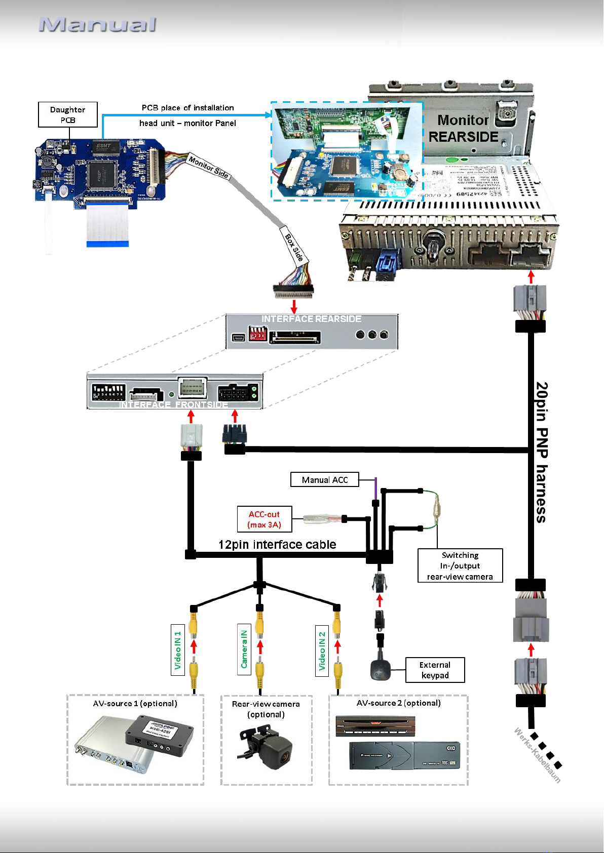
2.2. Connection schema
2.3. Connection to the head-unit
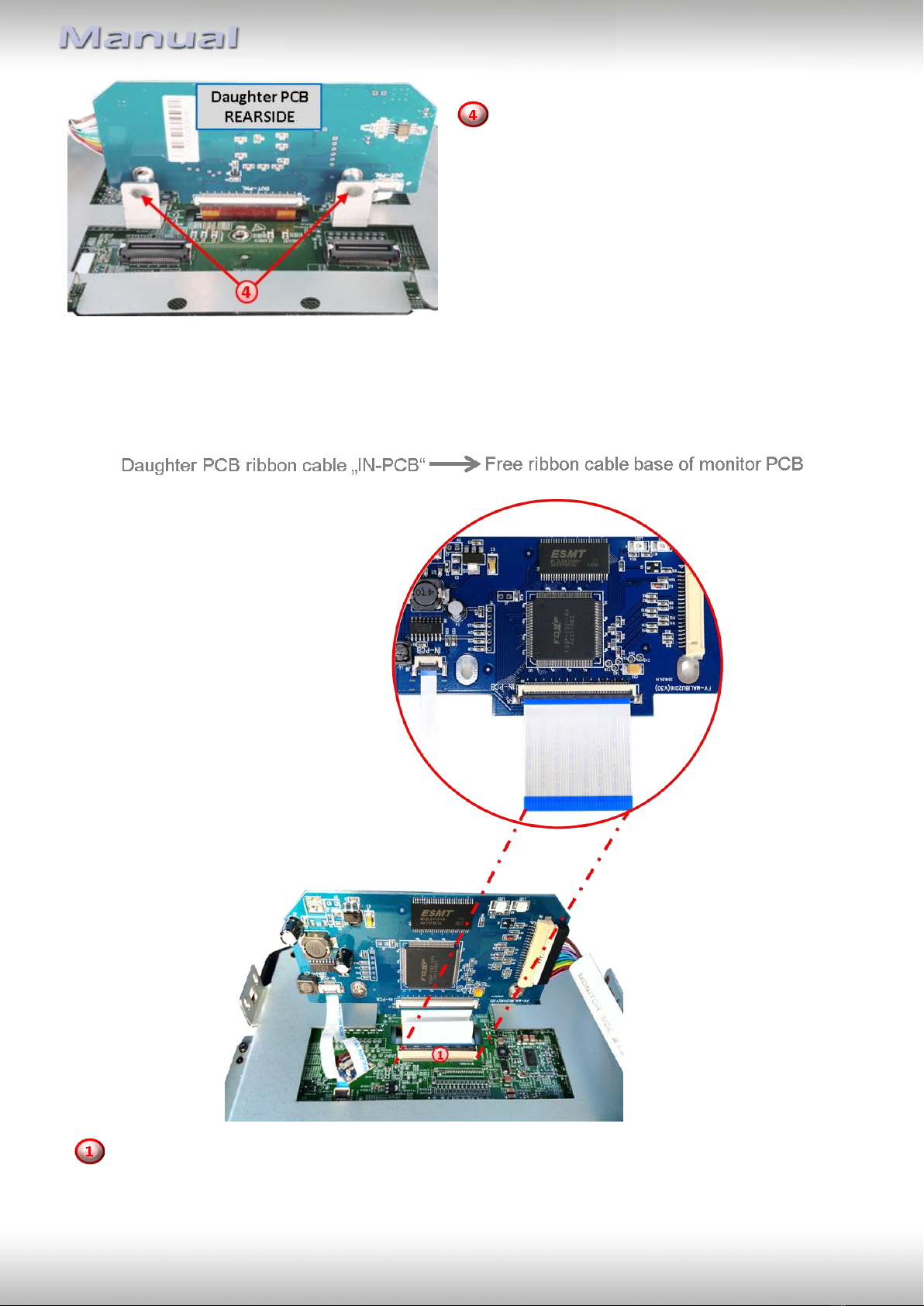
2.3.1. Installation of the Exchange –retaining plate and the daughter PCB
2.3.2. Connecting ribbon cables
2.3.2.1. Ribbon cable –66pin
2.3.2.2. Warning notes, concerning the installation of ribbon cables
2.4. Connection from monitor to the video interface
2.5. Connection to the head-unit –Power / CAN
2.6. Connecting video sources
2.6.1. Video-sources to Video IN1 and Video IN2
2.6.2. Audio-insertion
2.6.3. After-market rear-view camera
2.6.3.1. Case 1: Video-interface receives the reverse gear signal
2.6.3.2. Case 2: Video interface does not receive the reverse gear signal
2.6.3.3. Video signal connection for the rear-view camera
2.7. Connecting video-interface and external keypad
2.8. Picture settings and guide lines
3. Interface operation
3.1. By CALL OFF button
3.2. By keypad
4. Specifications
5. FAQ –Trouble shooting