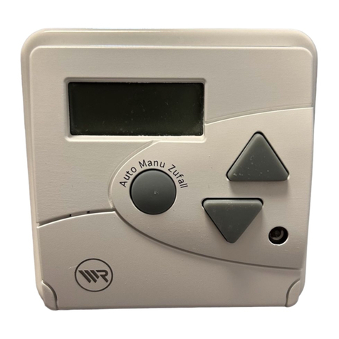
RADEMACHER Troll Comfort User manual

VBD 594-2 (01.21)
Item no. Troll Comfort / Troll Comfort 3D
3650 00 12 / 3650 07 12 (ultra-white)
3650 05 22 / 3650 07 22 (aluminium)
EN
Troll Comfort / Troll Comfort 3D
Instruction manual for the electrical connection and for commissioning
Type: 5625-UW, 5625-AL / 5635-UW, 5635-AL

2
EN
i
Contents
1. This manual...............................................................................5
1.1 How to use this manual .....................................................................5
2. Hazard symbols........................................................................6
2.1 Levels of danger and signal words.................................................6
2.2 Symbols and depictions used..........................................................7
3. Safety instructions...................................................................8
3.1 Intended use ..........................................................................................9
3.2 Improper use....................................................................................... 10
3.3 Expert knowledge required by the installer............................ 10
3.4 Glossary - definition ......................................................................... 11
4. Included in delivery.............................................................. 12
5. General view of the operating unit ................................... 13
5.1 General view of the installation housing.................................. 15
5.2 Electrical connections...................................................................... 16
5.3 Display and its symbols................................................................... 17
6. Product description.............................................................. 19
6.1 Description of the safety functions............................................. 20
6.2 Overview of functions ..................................................................... 21
7. Technical specifications....................................................... 23
7.1 Factory settings.................................................................................. 25
7.2 Conduct in the event of a power failure ................................... 27
8. Safety instructions for the electrical connection............ 28
8.1 Important information prior to the electrical
connection and installation........................................................... 30
8.2 Electrical connection........................................................................ 32
8.3 Connecting a tubular motor to the Troll Comfort ................. 33
8.4 Connecting a lamp to the Troll Comfort * ................................ 34
8.5 Connecting a tubular motor to the Troll Comfort 3D........... 35
9. Installation after the electrical connection...................... 36
10. Brief description of the standard display and
main menu ............................................................................. 37
3
EN
Contents
i
11. Introduction to opening the menus and
setting the functions............................................................ 38
12. Initial commissioning with the help of the
installation wizard ................................................................ 40
13. Manual operation ................................................................. 43
14. Moving to a target position................................................ 44
15. Menu overview...................................................................... 45
16. Menu 1 - Switching automatic mode on/off.................... 47
17. Switching times (opening and closing times) [ / ],
brief description.................................................................... 48
17.1 Menu 2 - Configuring opening and closing times [ / ] ... 52
18. Connecting a local light sensor.......................................... 56
18.1 Light sensor connection when using the
supplied frame .................................................................................. 57
18.2 Light sensor connection when using a frame supplied
by other manufacturers .................................................................. 58
18.3 Dismantling the light sensor......................................................... 60
19. Automatic dusk function,
brief description.................................................................... 61
19.1 Menu 3 - Customising the automatic dusk function............ 63
20. Automatic sun function, brief description....................... 65
20.1 Menu 4 - Configuring the automatic sun function ............... 67
21. Automatic dawn function,
brief description.................................................................... 69
21.1 Menu 5 - Customising the automatic dawn time.................. 70
22. Menu 6 - Configuring the random function .................... 71
23. Automatic wind function, brief description .................... 72
23.1 Menu 7 - Configuring the automatic wind function ............ 73
24. Automatic rain function, brief description ...................... 74
24.1 Menu 8 - Configuring the automatic rain function............... 75

4
EN
i
25. Menu 9 - System settings .................................................... 76
25.1 Menu 9.1 - Setting the time and date ........................................ 77
25.2 Menu 9.2 - Configuring the motor run time............................ 78
25.3 Menu 9.3 - Configuring the ventilation position ................... 80
25.4 Menu 9.4 - Setting the postcode ................................................. 82
25.5 Menu 9.5 - Configuring the switching time programme.... 83
25.6 Menu 9.6 - Configuring the blockage detection.................... 85
25.7 Menu 9.7 - Setting the Venetian blind mode .......................... 88
26. Menu 9.8 - Device settings.................................................. 90
26.1 Menu 9.8.1 - Switching the automatic summer/
winter time on/off............................................................................. 91
26.2 Menu 9.8.2 - Setting the display contrast................................. 92
26.3 Menu 9.8.3 - Setting the permanent display lighting .......... 92
26.4 Menu 9.8.3 - Setting the timer mode......................................... 93
26.5 Menu 9.8.5 - Switching the button lock on / off..................... 94
26.6 Menu 9.8.6 - Configuring the inputs E1/E2.............................. 95
26.7 Menu 9.8.7- Switching the reversal of rotation
direction on/off.................................................................................. 97
26.8 Menu 9.8.8 - Configuring the light function............................ 98
26.9 Menu 9.8.9 - Configuring the end points of the
tubular motor ...................................................................................101
26.10 Menu 9.8.0 - Displaying the software version.......................103
27. Deleting all settings, software reset................................104
28. Performing a hardware reset............................................105
29. Error messages ....................................................................106
30. Dismantling .........................................................................106
31. Time zone table...................................................................107
32. Simplified EU declaration of conformity ........................109
33. Accessories...........................................................................109
34. Warranty terms and conditions .......................................110
Contents

5
EN
i
1. This manual...
...describes how to install, connect the electrical system and operate the
Troll Comfort and the Troll Comfort 3D.
1.1 How to use this manual
◆Before you begin, please read this manual through completely and
follow all the safety instructions.
◆Please also read the instruction manuals for the accessories (if avail-
able) as well as the manuals for the respective connected electrical
appliances.
◆This manual is part of the product. Please store it in an easily accessi-
ble place.
◆When passing the Troll Comfort or Troll Comfort 3D on to a third
party, this manual must be passed on as well.
◆Damage resulting from non-compliance with this manual and the
safety instructions will void the warranty. We assume
no liability for any resulting damage.
i

6
EN
i
2. Hazard symbols
The following hazard symbols are used in this manual:
Danger to life resulting from electric shock
Danger area / dangerous situation
2.1 Levels of danger and signal words
DANGER!
This hazard will lead to serious injury or death if not avoided.
WARNING!WARNING!
This hazard may result in serious injury or death if not avoided.
CAUTION!
This hazard may result in minor or moderate injury if not avoided.
ATTENTION!
This hazard may lead to property damage.
i

7
EN
i
The wind or rain symbol is
only displayed in the main
menu if an external input
(E1 or E2) is configured for
the automatic wind or rain
function.
2.2 Symbols and depictions used
i
i
Other useful
information
Please read the respective
manual
1. Procedures
2.
◆Itemisation
1) or a) Lists
Activated menu symbols and setting
parameters flash on the display.
Information about opening the menus
and setting the parameters can be found
on page 38.

8
EN
3. Safety instructions
Danger due to electric shock when working on all electrical
systems.
◆The electrical connection and all work on electrical systems must
only be carried out by a qualified electrician in accordance with the
connection instructions in this manual.
◆Carry out all installation and connection work only in a de-energised
state.
The use of defective devices can lead to personal injury and
property damage (electric shocks / short circuiting).
◆Never use defective or damaged devices.
◆Check the Troll Comfort or Troll Comfort 3D for damage.
◆Please contact our Customer Service if you find any damage, see
page 112.
Improper use leads to an increased risk of injury.
◆Train all personnel to use the Troll Comfort or Troll Comfort 3D
safely.
◆Children must not play with the device.
◆Never remove the operating unit from the installation housing
during operation.
i

9
EN
3.1 Intended use
Use the Troll Comfort or Troll Comfort 3D exclusively as follows.
Application: Troll
Comfort
Troll
Comfort 3D
Connection and control of a tubular
motor for:
◆Roller shutters and awnings
◆Venetian blinds and slats
✓ ✓
Connection and control of an elec-
trical appliance ✓—
Electrical connection is possible
without neutral terminals —✓
Observe the permissible load limits, see page 23, Technical specifica-
tions.
Operating conditions
◆The tubular motor must be fitted with a mechanical or electronic
end position switch.
◆Only operate the Troll Comfort or Troll Comfort 3D in dry rooms
◆A 230 V/50 Hz power supply, together with a site-provided discon-
necting device (fuse), must be available at the installation location.
◆Troll Comfort 3D
The Troll Comfort 3D can only be operated in combination with tu-
bular motors with mechanical limit switches and with Rademacher
tubular motors with electronic limit switches from the year 2000
onwards.
i

10
EN
3.2 Improper use
Using the Troll Comfort or Troll Comfort 3D for purposes other than
those previously mentioned is not permissible.
Personal injury and property damage may occur if the Troll Comfort
is used to disconnect the connected appliance.
◆Do not use the Troll Comfort to disconnect the connected appliance.
There is a risk of fatal injury caused by short circuiting and
electric shocks if the Troll Comfort or Troll Comfort 3D is used
outside or in damp rooms.
Do not install and use the Troll Comfort or Troll Comfort 3D outside or in
damp rooms.
3.3 Expert knowledge required by the installer
The electrical connection, installation and commissioning of the Troll
Comfort and Troll Comfort 3D must only be carried out by a qualified
electrician in accordance with the instructions in this manual.
i
i

11
EN
i
3.4 Glossary - definition
UW
◆UW = ultra-white (device colour)
DIN 49075
◆German Standard "Cover panels for installation devices for building
into
device boxes..."
ELV
◆Extra low voltage

12
EN
i
4. Included in delivery
Included in delivery
a) 1 x Operating unit (50 x 50 mm)
b) 1 x Frame
c) 1 x Installation housing
d) 1 x Spacer frame, see page 36
e) 1 x Instruction manual (not illustrated)
After unpacking please check and compare...
... the contents of the package with those specified above.
Accessories optionally available, see page 109
f) 1 x Light sensor
a)
b) c)
d)
f)

13
EN
i
5. General view of the operating unit
1)
Pos. Symbol Description
1) Operating unit
2) Display
3)
M
Menu button
◆Open the main menu
◆Back to the previous menu or standard display
4) Setting buttons
◆Select a menu in the main menu
◆Set the parameters (more / less)
●Short press or press and hold = gradual or
quick setting
◆Switch functions on / off (On / OFF)
◆Move to a target position
3) 4)
5)
6)
7)
8)
9)
2)
10)

14
EN
Pos. Symbol Description
5)
OK
OK button
◆Open the selected menu
◆Confirm and save settings
◆Continue to the next setting
6) Operating buttons Up / Down
◆Manual operation
7)
8) SET/Stop button
◆Manual stop of the roller shutter travel
◆Set (adjust) various functions
9) Bridging contact for a hardware reset
◆See page 105
10) Connection socket for the light sensor
◆See page 57, Installation
5. General view of the operating unit
i

15
EN
5.1 General view of the installation housing
11)
12)
Pos. Symbol Description
11) Installation housing
12) Claw fasteners and screws
13) Connecting terminals
14) Type plate (example for the Troll Comfort)
i
14)
13)

16
EN
15)
Pos. Symbol Description
15) /
16)
LTroll Comfort 3D
Power supply - 230 V / 50 Hz
Electrical connection is possible without neutral
terminals.
15) L / N Troll Comfort
Power supply - 230 V / 50 Hz, 60 Hz
16) E1 / E2 Troll Comfort - external inputs - optional
Connect external signal transmitters, e.g. Venetian
blind switches/external sensors etc., see page 33 /
34.
Both inputs are independently configured, see page
95.
17) / Rotation direction (up / down)
Connecting cables to the tubular motor.
5.2 Electrical connections
16)
i
17)
LL L
Troll Comfort 3D
Troll Comfort

17
EN
i
Symbol Description
MO ... SO Weekdays (Monday ... Sunday)
Time / setting parameters
Information
Switching time programme
OFFSET Offset (for astro time)
SET Setting
AUTO Automatic mode
PLZ Postcode
IST Actual value
Direction of travel (up/down)
Automatic mode off
Switching times
Automatic dusk function
5.3 Display and its symbols

18
EN
Symbol Description
Automatic sun function
Automatic dawn function
Random function
Automatic wind function *
Automatic rain function *
System settings
SOLL Set value
Automatic slat adjustment
T Jog mode
LLight function *
NORMAL Switching modes (NORMAL / ASTRO / SENSOR)
Blockage detection *
%Position (in percent)
Automatic button lock
* not available for the Troll Comfort 3D
i
5.3 Display and its symbols

19
EN
i
6. Product description
The Troll Comfort and Troll Comfort 3D are designed for controlling
roller shutters, Venetian blinds, slats or awnings by connecting a corre-
sponding tubular motor.
Roller shutter control
The device enables the roller shutter to be automated.
Manual operation
It is possible to manually control the connected tubular motor at any
time by using the controls.
Troll Comfort (not for the Troll Comfort 3D)...
◆with a light function
If required, you can connect a lamp, for example, or other electrical
appliances to the Troll Comfort instead of a tubular motor and use
the light function to control it.
◆as a central controller for several Troll Standard controllers
The Troll Comfort can also be used as a central controller for several
Troll Standard controllers, as an alternative to connecting a tubular
motor. You can obtain additional connection and circuit examples
from our website: www.rademacher.de
◆with an external controller via the two inputs E1 and E2
The Troll Comfort has two configurable inputs E1 and E2 (230 V / 50
Hz) for connecting external signal transducers (e.g. Venetian blind
switches / external sensors etc.), see page 33 / 34.
Both inputs are independently configured, see page 95.

20
EN
i
Installation and electrical connection
The Troll Comfort and Troll Comfort 3D are designed as a flush-mount-
ed device for indoor rooms. The electrical connection is carried out by
means of the connecting terminals on the reverse side of the installa-
tion housing.
Installation / compatible switch ranges
The Troll Comfort and Troll Comfort 3D can be integrated into standard
switch ranges (50 x 50 mm).
i
It may be necessary to use an intermediate frame * 50 x 50
(according to DIN 49075) depending on the switch range
used.
* Not included
6. Product description
6.1 Description of the safety functions
Troll Comfort with blockage detection *
The Troll Comfort is able to monitor the torque of motors equipped with
a mechanical end point setting. This enables the controller to switch off
the motor in the event of overloading or blockage, see page 85.
* not available for the Troll Comfort 3D
i
Other manuals for Troll Comfort
1
This manual suits for next models
5
Table of contents
Other RADEMACHER Controllers manuals

RADEMACHER
RADEMACHER DuoFern 9471-1 User manual

RADEMACHER
RADEMACHER Troll Comfort Service manual

RADEMACHER
RADEMACHER DuoFern 9482 User manual

RADEMACHER
RADEMACHER DuoFern 9494-1 User manual

RADEMACHER
RADEMACHER DuoFern 9494-3 Installation and operation manual

RADEMACHER
RADEMACHER DuoFern 3500 30 64 Guide

RADEMACHER
RADEMACHER DuoFern Universal 9470-1 User manual

RADEMACHER
RADEMACHER HomePilot Installation and operation manual

RADEMACHER
RADEMACHER RolloTron Swivel Winder Comfort 1500 Product guide

RADEMACHER
RADEMACHER 9470-4 User manual