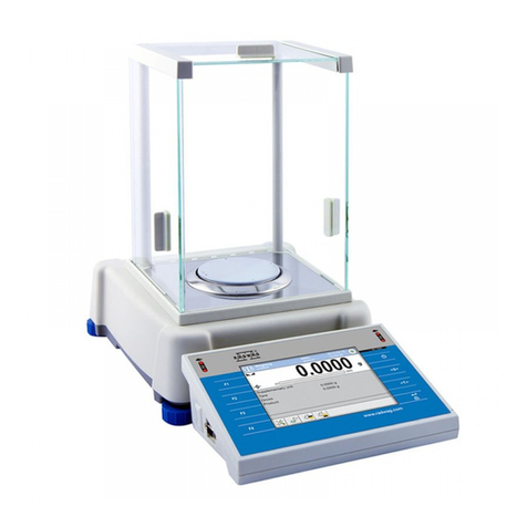
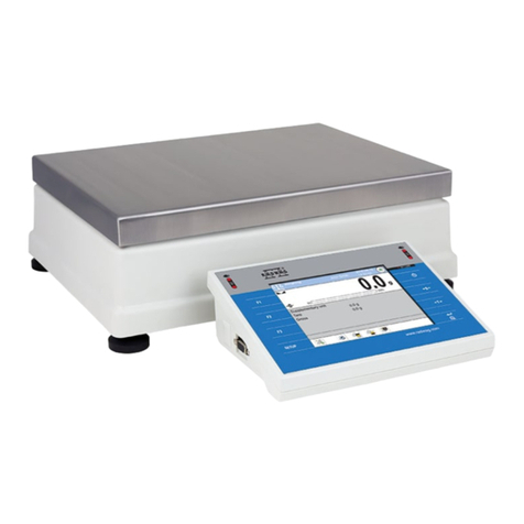
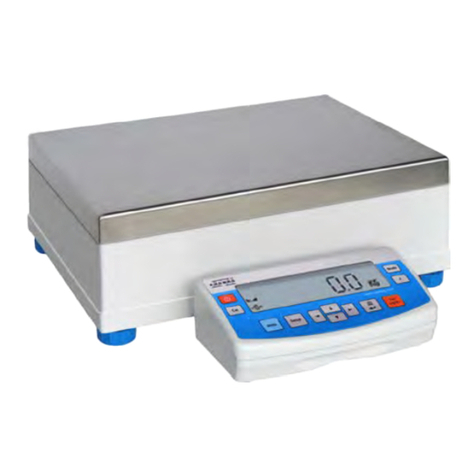
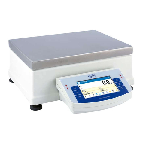
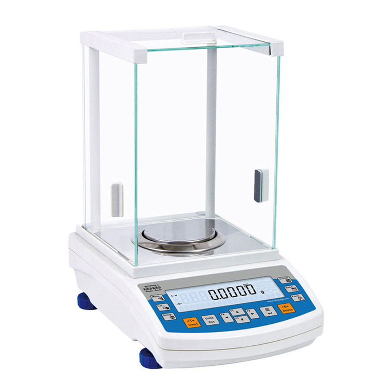
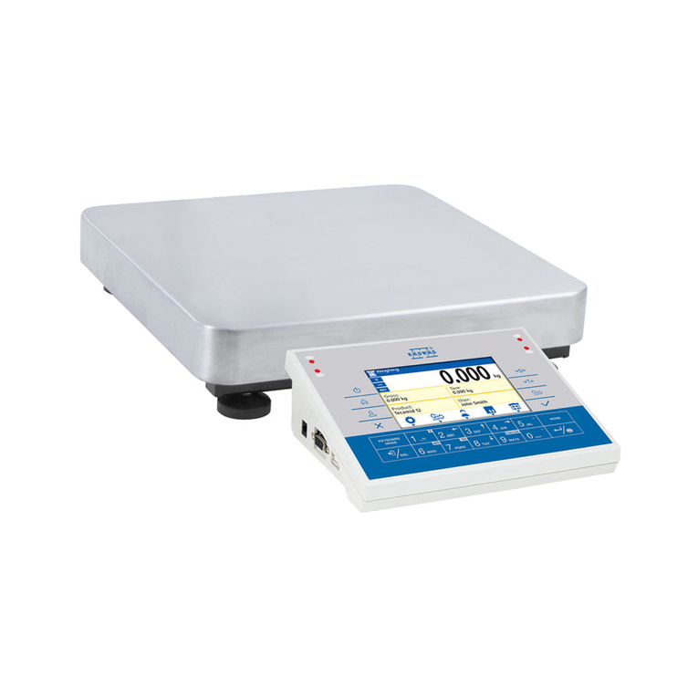
RADWAG MYA.3Y User manual

- 1 -
User manual no.:
LMI-61-05/04/13/ENG
Balances
3Y series
• Microbalances – MYA.3Y
BALANCES AND SCALES
RADWAG 26 – 600 Radom, Bracka 28, POLAND
Phone: +48 (0-48) 38 48 800, fax. +48 (0-48) 385 00 10
export@radwag.com
www.radwag.com

- 2 -
APRIL 2013

- 3 -
TABLE OF CONTENTS
1. BASIC INFORMATION.............................................................................................6
1.1. Intended use .................................................................................................................. 6
1.2. Precaution measures ..................................................................................................... 6
1.3. Warranty ........................................................................................................................ 6
1.4. Supervision over balance metrological parameters ........................................................ 6
1.5. Manual significance ...................................................................................................... 6
1.6. Balance user training ..................................................................................................... 6
2. TRANSPORT AND STORAGE.................................................................................7
2.1. Packaging ...................................................................................................................... 7
3. UNPACKING, INSTALLATION AND COMMISSIONING.........................................7
3.1. Installation and place of use .......................................................................................... 7
3.2. Unpacking ..................................................................................................................... 9
3.3. Balance cleaning ......................................................................................................... 10
3.4. Plugging to mains ........................................................................................................ 10
3.4. Connecting peripheral equipment ................................................................................ 10
4. GETTING STARTED...............................................................................................11
5. BALANCE LEVELING............................................................................................11
5.1. Level control system – automatic operation – “ALERT” mode ...................................... 12
5.2. Manual leveling ............................................................................................................ 13
6. MENU STRUCTURE...............................................................................................14
6.1. Working mode selection .............................................................................................. 14
6.2. Moving in user menu ................................................................................................... 15
6.3. Return to weighing mode ............................................................................................. 15
6.3. Quick return to weighing mode .................................................................................... 16
7. WEIGHING..............................................................................................................19
7.1. Zeroing process ........................................................................................................... 19
7.2. Tarring process ............................................................................................................ 19
7.3. Use of constant tare in weighing .................................................................................. 20
7.4. Applying automatic tare in weighing ............................................................................. 22
7.5. Digital tare ................................................................................................................... 22
8. BASICS ON TERMINAL AND SOFTWARE OEPRATION.....................................23
8.1. Basics on balance operation ........................................................................................ 26
9. BALANCE SOFTWARE..........................................................................................27
9.1. Operators / User profiles .............................................................................................. 27
9.2. System settings ........................................................................................................... 27
9.3. Working modes ............................................................................................................ 28
10. BALANCE ADJUSTMENT....................................................................................29
10.1. Adjustment report settings ......................................................................................... 31
10.2.Adjustment history ...................................................................................................... 31

- 4 -
11. DISPLAY CALIBRATION .....................................................................................32
12. BALANCE USER SELECTION.............................................................................32
13. PERIPHERALS.....................................................................................................33
14. ABOUT..................................................................................................................33
15. COMMUNICATION ...............................................................................................34
16. UPDATE................................................................................................................34
17. LEVELING.............................................................................................................34
18. BALANCE ADAPTATION – USER SETTINGS....................................................35
18.1. Adding a new operator ............................................................................................... 36
18.2. Deleting a operator .................................................................................................... 36
18.3. Selecting a operator ................................................................................................... 36
18.4. Operator settings ....................................................................................................... 36
18.4.1. User details ................................................................................................................................... 37
18.4.2. Look .............................................................................................................................................. 38
18.4.3. Readout ........................................................................................................................................ 39
18.4.4. Operation of buttons ..................................................................................................................... 40
18.4.5. Date / Time ................................................................................................................................... 41
18.4.6. Printouts – standard printout template .......................................................................................... 42
18.4.6.1. Quick enabling Print Header and Print Footer buttons ............................................................... 45
18.4.7. Printouts – Non-standard printout ................................................................................................. 46
18.4.8. Units .............................................................................................................................................. 50
18.4.9. Working Modes – general information .......................................................................................... 51
18.5. Quick access to determining working modes parameters .......................................... 52
18.6. Parameter of working mode WEIGHING – quick access keys ................................... 53
18.7. Parameter of working mode WEIGHING – information .............................................. 54
18.8. Parts Counting ........................................................................................................... 57
18.8.1. Parts counting – quick access keys .............................................................................................. 57
18.8.2. Creating database of standards .................................................................................................... 61
18.8.3. ACAI function – Automatic Accuracy Correction ........................................................................... 62
18.8.4. Parameters of parts counting mode – information ........................................................................ 63
18.8.5. Graphic interpretation of Dosing and Checkweighing modes ........................................................ 65
18.9. Checkweighing .......................................................................................................... 67
18.9.1. Creating database of checkweighing thresholds ........................................................................... 68
18.9.2. Use of checkweighing thresholds .................................................................................................. 69
18.9.3. Bargraph in checkweighing mode. ................................................................................................ 71
18.10. Dosing ..................................................................................................................... 71
18.10.1. Creating database of target values ............................................................................................. 72
18.10.2. Use of target values. ................................................................................................................... 73
18.10.3. Bargraph in dosing mode ............................................................................................................ 75
18.11. Percent setup .......................................................................................................... 76
18.11.1. Creating database of reference mass (standards) ...................................................................... 79
18.11.2. Use of reference mass (standard) in weighing. ........................................................................... 81
18.11.3. Use of reference mass values in weighing .................................................................................. 82
18.12. Animal weighing....................................................................................................... 83
18.12.1. Internal settings of the animal weighing mode ............................................................................ 84
18.12.2. Animal weighing mode – manual mode of operation .................................................................. 85
18.13. Density of solids, liquid and air ................................................................................. 86
18.13.1. Setting a default function of the density determining mode ......................................................... 87
18.13.4. Density of air ............................................................................................................................... 88
18.14. Formulations ............................................................................................................ 89
18.14.1. Designing a formulation .............................................................................................................. 90
18.14.2. Use of database of formulations in weighing. .............................................................................. 91
18.15. Statistics .................................................................................................................. 93
18.15.1. Internal menu of Statistics mode ................................................................................................. 94
- 5 -
18.16. Mass Comparison .................................................................................................... 95
18.16.1. Select method for comparing mass ............................................................................................. 96
18.16.2. Mass comparison - measurements ............................................................................................. 97
18.16.3. Mass comparison – report from a measuring series ................................................................... 98
18.17. Differential weighing .............................................................................................. 100
18.17.1. Defining a series ....................................................................................................................... 103
18.17.2. An example of carrying out a differential weighing process ...................................................... 105
18.17.3. Copy tare .................................................................................................................................. 112
18.17.4. Use of “SAMPLE SELECTION” function. .................................................................................. 112
18.17.5. Deleting a value ........................................................................................................................ 113
19. ACCESS TO BALANCE PARAMETERS...........................................................114
19.1. Determining authorization password ........................................................................ 114
19.1.1. Assigning password to an administrator ..................................................................................... 115
20. TECHNICAL DATA.............................................................................................116
20.1. Balance MYA .3Y series .......................................................................................... 116
APPENDIX A – cooperation with EPSON printer ..................................................117
Changing baud rate settings ................................................................................................................... 117
APPENDIX B – cooperation with KAFKA printer ..................................................118
Changing baud rate settings in a balance ............................................................................................... 118
APPENDIX C – cooperation with label printer CITIZEN........................................119
Phase I – designing a label ..................................................................................................................... 119
Phase II – transferring a label to a balance ............................................................................................. 121
Phase III – printing a label ...................................................................................................................... 123
APPENDIX D – databases.......................................................................................124

- 6 -
1. BASIC INFORMATION
1.1. Intended use
Balances 3Y series are intended to precise mass measurement of weighed
loads conducted in laboratory conditions. It is designed only for non-automatic
weighing processes, thus the material to be weighed needs to be placed on the
center of balance’s weighing pan with required carefulness.
1.2. Precaution measures
Never use the balance 3Y series is areas endangered with explosion. Balance
3Y series is not designed to operate in EX zones. Do not make any changes in
balance structure.
1.3. Warranty
Warranty does not cover the following cases:
• Balance defects if it is utilized contrary to its intended use,
• Balance defects, if service claims removing or destroying product’s protective
stickers which protect the balance’s housing against unauthorized access.
• Mechanical defects or defects caused by liquids and natural wear,
• Balance defects caused by inappropriate setting of a defect of electric power
network,
• Defects caused by overloading balance’s mechanical measuring system.
1.4. Supervision over balance metrological parameters
Metrological parameters of a balance need to be checked by a user in
determined time intervals. Inspection frequency is conditioned by ambient
conditions in which a balance is used, type of carried out processes and adopted
quality management system.
1.5. Manual significance
It is very important to read the user manual carefully before switching on and
starting up balance operation, even if the user is experienced and has worked
with the this type of balance before.
1.6. Balance user training
A balance should be utilized and supervised only by users who are trained and
experienced in using this type of weighing instruments.

- 7 -
2. TRANSPORT AND STORAGE
2.1. Packaging
Retain all elements of balance packaging in case they are needed for future
balance transporting. Only an original balance packaging can be used for
transporting a balance. Before packaging, disconnect all cables and conductors from
the balance and remove any moveable parts from the weighing chamber (weighing
pan, shields, inserts). Balance components should be packed into their original
packaging for their proper protecting against possible damage during transport.
3. UNPACKING, INSTALLATION AND COMMISSIONING
3.1. Installation and place of use
− Balance should be stored and used in rooms free from any vibrations and
shocks, with no air movement and undusted,
− Ambient air temperature in a weighing room should not exceed the range
specified on balance data plate. Temperature changes should be of laminar
structure, and permissible temperature change ratio should not exceed 0,5
°C/h
− Air humidity should contain within 35% - 80%; maximum humidity change rate
5% / h,
− A balance should be placed on a wall console or a stable workbench, free
from vibrations and distant from heat sources,
− Pay special attention to weighing magnetic materials. In case such loads are
to be weighed, use the option of under-hook weighing. The hook for
assembling an under-hook weighing kit is located in the balance base,
− In case static electricity may have effect on balance indications, ground the
balance using the grounding bolt located at the back side of balance base.
− A microbalance MYA 5/3Y/F1 series is intended to determine mass of filters
with maximum diameter of 160mm.
The material of the tested sample is highly electrostatic, thus it requires
applying special measures protecting against static electricity. In case of
carrying out a weighing process in low humidity conditions, it is advisable to
use an additional air ionizer. Such a large surface of the weighed object, in
case of materials like paper that is highly hygroscopic, causes occurrence of
weighing error of several hundreds of reading intervals. Thus it is highly
important to ensure required ambient conditions for balance operation (such
as those listed in the product folder):

- 8 -
Working temperature: 10-40 °C
Relative air humidity: 45% - 65%
Because of the structure of the objects to be weighed, it may be necessary to
store them in glass containers for eliminating the phenomenon of humidity
absorption. As the value of repeatability error increases along with the
weighing pan diameter, the balance also features an additional regular
weighing pan intended to determine mass of standard materials, and testing
the balance with exclusion of any ambient conditions impact on the weighed
object.

- 9 -
3.2. Unpacking
Carefully remove the balance from its packaging, remove the plastic and foil
transport protective elements. Gently place the balance in its intended place of use.
Install the weighing pan, and other elements according to below scheme.
Microbalance MYA 3Y series
After installing the balance in its intended place of use assemble its components following
above scheme and in relation to balance type.
A – standard
1. anti-draft shield
2. bottom ring
3. weighing pan
4. glass top cover of the weighing chamber
B – balance MYA 0,8/3.3Y series
Apart from the standard execution (A) the
balance is available with a pan for weighing
filters.
1. anti-draft shield
2. bottom ring
9. pan for weighing filters
4. glass top cover of the weighing chamber
C – balance for weighing filters
2. bottom ring
10. pan for weighing filters
11. weighing pan
D – balance for pipette calibration
1. anti-draft shield
2. bottom ring
3. weighing pan
4. glass top cover of the weighing chamber
5. glass vessel
6. additional container for water
(evaporation ring)
7. glass top cover of the weighing chamber
with an opening
8. additional glass cover

- 10 -
After the elements setting, connect any additional devices and only then plug the balance
to power source. Power socket is located on back side of balance terminal containing the
display.
Balance for pipette calibration:
After
balance start up change the standard weighing pan into the one for placing a glass
vessel (5) and on stabilization of mass indication press TARE button.
3.3. Balance cleaning
Clean the balance using a damp ch by gentle rubbing any contaminated places.
Remember to remove the weighing pan and its shields from the weighing chamber
before their cleaning.
CAUTION:
Cleaning balance’s weighing pan if installed may damage instrument’s measuring
mechanism.
3.4. Plugging to mains
The balance should be plugged to mains using the original power adapter, which
is balance’s standard equipment. Plug the power adapter’s plug to balance’s socket
located at the back of the housing.
3.4. Connecting peripheral equipment
Use only accessories and peripheral equipment recommended by the
manufacturer of your balance. The balance must be unplugged from the mains
before connecting or disconnecting any peripherals (printer, PC computer, computer
keyboard). On connecting the peripherals, plug the balance to mains.

- 11 -
4. GETTING STARTED
Switching on the balance:
Press «On/Off» button on terminal overlay. The balance carries out
an internal testing procedure, and after its completing it is ready for
use.
Caution:
If the balance is incorrectly leveled,
then on switching on it displays a
alert ordering leveling the balance.
The leveling procedure on described
in ch. 5.
If a balance is turned off by
pressing «On/Off» button, then its
restart is carried out by:
repeated pressing of the
«On/Off» button, or
touching an OPTIONAL
place on the display area
Switching off the balance:
Press «On/Off» button on terminal overlay. The display is blanked,
and a signal diode lights up.
5. BALANCE LEVELING
The balance 3Y series feature a built-in electronic level sensor that continuously
monitors balance’s level status during its operation. On detecting any level change
the sensor indicates a command for readjusting the level. The level status is
continuously indicated in the upper right corner of balance’s display, next to date and
time.
CAUTION:
The first leveling of a balance using the electronic level can be carried out after 2
hours from plugging the balance to mains. This time interval is needed to thermally
stabilize the measuring section of the level monitoring system. Within this time
interval, the level monitoring pictogram visible in the upper bar of the display is
flashing. After activating the level control function the blue coloured dot of level status
is not displayed in the level control pictogram.

- 12 -
5.1. Level control system – automatic operation – “ALERT” mode
If the level sensor detects any level change, then
the colour of the level pictogram on the display
changes into red (colour of the smallest dot in
level pictogram), and an alert message is
displayed.
In order to level the balance press “ENTER”
button in the displayed message box.
The display changes into a control panel of the
leveling function with a top view of current level
status visible on its right side, and balance
elevation on the left. The balance pictogram is
accompanied by flashing arrows indicating a
direction for turning the balance’s adjustable feet
to restore the level status. Balance pictogram
depends on its model.
The level status and arrows directions are changing immediately on level adjusting
process thus facilitating a user in restoring the level status. A red coloured dot
indicates current level status of a balance. The adjustable feet should be turned
according to the direction indicated by arrows on the control panel, so that the dot of
the level indicator moves to the center of the inner circle of the level view.
When the dot moves to the center of the inner
circle of the level pictogram, the balance is
leveled correctly. Press OK button to accept the
settings.
Exit the level adjusting function and return to
weighing mode by pressing “OK“ button in the
bottom bar of the display.

- 13 -
5.2. Manual leveling
If the electronic level control function is disabled in balance menu, then in case
of level change a balance user has to manually enable the leveling procedure.
Press pictogram of the level status. The display
changes into a control panel of the leveling
function with a top view of current level status
visible on its right side, and balance elevation on
the left. The balance pictogram is accompanied
by flashing arrows indicating a direction for
turning the balance’s adjustable feet to restore
the level status. Level the balance and then
press “OK” button to accept settings.
If the balance is leveled correctly then the colour
of the level pictogram visible in the upper right
corner of the display is green.

- 14 -
6. MENU STRUCTURE
6.1. Working mode selection
Each balance operator can set their individual working mode enabled as DEFAULT on
activating their profile.
As a result, the balance starts operation with a working mode specific for an enabled
user profile, i.e. in parts counting mode or percent setup. The working mode can be
easily changed to another in an optional moment during balance operation:
PROCEDURE:
o in an optional moment press working mode
pictogram
o the display opens a window including a list of
all available working modes.
o Press field with a name of a working mode to
be used,
o The display switches to the enabled working
mode with a set of QUICK ACCESS KEYS
present in the bottom display bar.
Data indicated in the GREY coloured workspace
area is dependent on the settings of the
“INFORMATION” menu accessed by pressing the
workspace area on the display.
The Quick Access Keys visible in the bottom bar
of the display are dependent on the settings of
“KEYS” menu.
The internal settings of “Information” and “Keys”
functions may differ in each of the working modes.
In practice, on enabling a working mode, the
following may change:
Grey coloured workspace area with
displayed information (and descriptions),
and
Quick access keys specific for the enabled
working mode.
Assigning information and keys to an individual
working mode enables creating a dedicated
weighing application designed for an exact
purpose or user requirements.

- 15 -
6.2. Moving in user menu
A balance 3Y series features a colourful touch screen display making balance
software operation very simple and intuitive.
or Enter main menu
Quick scrolling menu to the top
Scroll menu upwards
Scroll menu downwards,
Quick scrolling menu to the bottom
Accept changes
Leave a function unchanged (without saving changes)
Add item to a database (e.g. database of operators)
Delete item from a database
6.3. Return to weighing mode
Changes in instrument’s memory are saved permanently on returning to
weighing mode with procedure of saving changes.
Press button for a few times until the display indicates below message box:
On displaying the message box select one of available options:
– accept changes, or
– abandon changes and exit.

- 16 -
6.3. Quick return to weighing mode
The software enables quick returning from an optional menu section with or
without saving made changes.
Return to menu WITHOUT saving changes.
Press and hold button for app. 2 sec. located in the upper right corner of the
display. The software returns to mass displaying window.
Return to menu WITH saving changes.
The process is enabled when returning from the following menu sections:
Peripherals, Adjustment, Operators, Communication, About (System info), Update,
and Leveling.
Press and hold (~2s) the upper left corner of the display (with mode pictogram
and menu descriptions). The software returns to displaying the main menu.
Then, press button which opens a message box for accepting / abandoning
the changes. Select one of available options, depending on the needs.
Caution: Parameter changes made inside of some functions do not require accepting, as
setting a parameter value is equal to accepting the parameter settings.

- 17 -
User menu structure comprises 8 main groups accessed by pressing SETUP
button on terminal overlay or pictogram on the touch screen display.
Adjustment
Internal adjustment
External adjustment
User adjustment
Adjustment test
Automatic adjustment
Adjustment time interval
Adjustment reprot printout
Adjustment report settings
Adjustment history
Touch panel calibration
Function
Operators
Max 10 user profiles
Peripherals
Printers
Barcode scanner
External communication
RS 232 [1]
RS 232 [2]
About
Balance ID
Balance type
Software rev.
Last adjustment
Temperature
Print settings
Communciation
Network
IP address
Subnet mask
Gate address
Update
Application
Printers
Language
Server
Leveling
Settings
Leveling
Database
Products
Operators
Weighing data
Clients
Controls
Average tares
Packages
Warehouses
Labels
ID Definitions
Formulations
The menu group of the largest content is the OPERATORS. It contains below
submenu for determining balance parameters to the needs of a user.

- 18 -
− User parameters
user
password
language
administrator
print settings
copy settings
− Menu look
colour
screen brightness
additional display brightness
beep sound
− Readout
filter
value release
refreshment
autozero
last digit
− Keys and sensors
left proximity sensor
right proximity sensor
sensor sensitivity
sensor sound
keyboard sound effect
− Date/Time
date format
time format
time
date
show time
show date
− Printout
standard printout
ο header
ο line
ο footer
non-standard printout
ο texts
ο printouts
code page
printout cut
− Units
Basic measuring units
Supplementary unit
− Working modes
Weighing
Dosing
Density
Mass comparator
Parts counting
Percent setup
Formulas
Differential weighing
Checkweighing
Animal weighing
Statistics
− Access level

- 19 -
7. WEIGHING
Simple weighing process is carried out using only the buttons located on the
right hand side of the balance terminal. The balance features separate buttons for
zeroing, tarring and generating a printout.
7.1. Zeroing process
Pressing the zeroing button causes determining a new zero point
for a balance. From now on mass of all loads placed on balance
weighing pan (including tare) is determined from this point. After
zeroing the displayed indication, the tare and net (gross) values
equals 0. A good weighing practice requires that before starting a
new process the indication is always zeroed by pressing the
zeroing button, and in particular before determining a tare value.
The zeroing range covers +/- 2% of the maximum capacity of a
balance.
7.2. Tarring process
Press TARE button – pictogram “Net“ appearing on the display
informs that all mass indications are subject to applied tare, and
thus are “net” values.
Note: Tarring negative values is impossible and causes displaying an
error message. In such case zero balance indication and repeat tarring
process.
WEIGHING
Load an object to be weighed on balance weighing pan. On stabilization of
indication read the measured result. If prior to weighing process a TARE was applied,
the display indicates Net pictogram.

- 20 -
7.3. Use of constant tare in weighing
If a weighing process applies a set of the same packages with determined mass
then the balance enables determining a constant tare. On weighing process the
constant tare value is recalled by pressing a dedicated QUICK ACCESS KEY. The
value of indicated measurement result is net, i.e. displayed with already applied
tare.
PROCEDURE – recall tare
o In an optional moment press a
QUICK ACCESS KEY
o The display opens a window with a
list of all saved tare values
o Press name or code of a selected
tare – it is automatically
RECALLED to be used
o The display indicates the tare value
proceeded by a minus sign.
PROCEDURE – save tare
o Press a QUICK ACCESS KEY
o The display opens a window with a
list of all saved tare values
o Press PLUS pictogram
o The tare value is added to the
database of tare values
o Press and hold a bar with tare
name
o the display shows fields related to
the selected tare,
o Give name and code of a tare
xxxxxxxxxxxx
As the number of tare values in use may be high, the balance enables:
− Sorting the database by: name, code
− Selecting database items by: name or code
− Editing and changing items in the database of packages
− Printing database items
− Exporting database items to a .csv file
− Importing database items
PROCEDURE
o In an optional working mode press
grey coloured workspace area
o The display opens a window with
an internal menu
o Scroll down to TARE field
o Press TARE field
Caution:
Menu “Tare“ enables saving values of tares
that are accessible on pressing a Quick
Access Key “Tare”.
This manual suits for next models
10
Table of contents
Other RADWAG Scale manuals

RADWAG
RADWAG WTC 6 User manual

RADWAG
RADWAG UYA 5Y User guide

RADWAG
RADWAG XA 5Y.M.A User guide

RADWAG
RADWAG HTY 15 C1/K User manual

RADWAG
RADWAG WTC 200 User guide

RADWAG
RADWAG ITKU-20-02-01-12-A User manual

RADWAG
RADWAG WTB series User manual

RADWAG
RADWAG WPT/4 User manual

RADWAG
RADWAG 3Y Series User manual

RADWAG
RADWAG WTC/L series User manual

RADWAG
RADWAG AS R2 PLUS User guide

RADWAG
RADWAG HX5.EX User manual

RADWAG
RADWAG PS 3000.R2 User manual

RADWAG
RADWAG WTC 200 User manual

RADWAG
RADWAG HRP.R Series User manual

RADWAG
RADWAG PS X7.M User guide

RADWAG
RADWAG WTC series User manual

RADWAG
RADWAG UYA 4Y User manual

RADWAG
RADWAG XA 4Y.A PLUS User guide

RADWAG
RADWAG TWM4 User manual