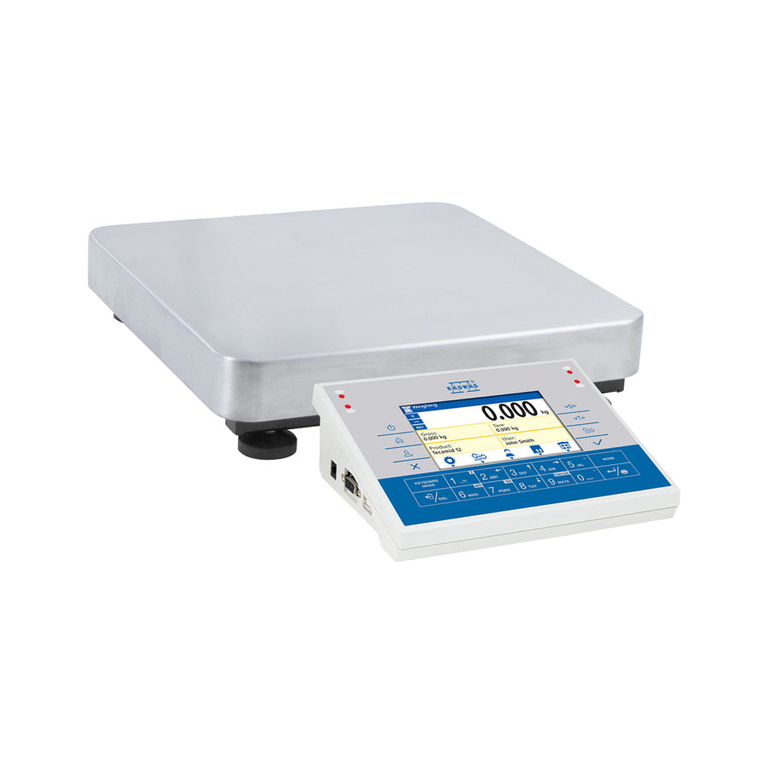
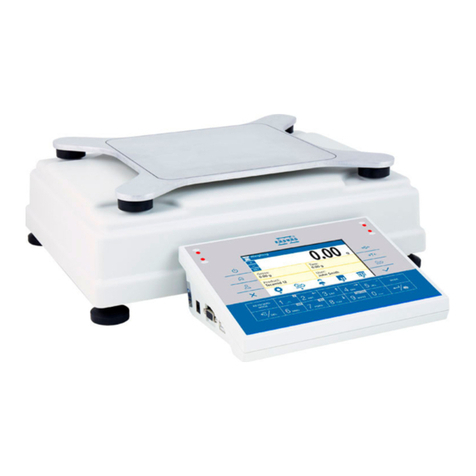
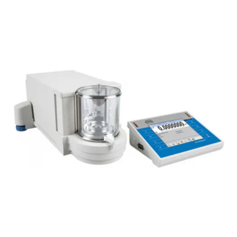
RADWAG 3Y Series User manual

User manual no.:
IMMU-02-03-04-14-ENG
BALANCES 3Y SERIES
−ultra-microbalances UYA 3Y
−analytical balances XA 3Y
−analytical balances XA 3Y.A
−analytical balances AS 3Y
−precision balances PS 3Y
−precision balances APP 3Y
BALANCES AND SCALES
RADWAG 26 – 600 Radom, Bracka 28, POLAND
Phone: +48 (0-48) 38 48 800, fax. +48 (0-48) 385 00 10
export@radwag.com
www.radwag.com

- 2 -
APRIL 2014

- 3 -
Table of contents
1. BASIC INFORMATION ....................................................................... 8
2. UNPACKING AND INSTALLATION.................................................... 10
2.1. Ultra-microbalaces UYA 3Y .................................................................... 10
2.2. Balances XA 3Y; XA 3Y.A ....................................................................... 11
2.3. Balances AS 3Y series ........................................................................... 12
2.4. Balances PS 3Y series ........................................................................... 13
2.5. Balances APP 3Y series ......................................................................... 13
2.6. Balance cleaning .................................................................................. 14
2.7. Plugging to mains ................................................................................. 20
2.8. Connecting peripheral equipment ........................................................... 20
3. BALANCE DESIGN ........................................................................... 21
3.1. Dimensions ......................................................................................... 21
3.2. Interfaces ............................................................................................ 25
4. STARTUP......................................................................................... 26
5. BALANCE KEYBOARD – FUNCTION KEYS ......................................... 26
6. SOFTWARE STRUCTURE .................................................................. 27
7. SOFTWARE WEIGHING WINDOW.................................................... 28
8. LOGGING ........................................................................................ 29
9. OPERATING USER MENU ................................................................. 31
9.1. Terminal’s keyboard ............................................................................. 31
9.2. Return to weighing mode ...................................................................... 32
10. WEIGHING...................................................................................... 33
10.1. Selection of measuring unit ................................................................... 33
10.2.Means of correct weighing procedure ...................................................... 34
10.3. Balance leveling ................................................................................... 35
10.4. Zeroing ............................................................................................... 35
10.5. Tarring ................................................................................................ 36
10.6. Weighing on dual range balances (ref. balance PS 200/2000.3Y series) ...... 37
10.7. Use of air buoyancy compensation factor ................................................. 37
10.8. Additional parameters on weighing process ............................................. 41
10.9.Minimum sample .................................................................................. 43
11. ADJUSTMENT .................................................................................. 47
11.1. Internal adjustment .............................................................................. 47
11.2. External adjustment ............................................................................. 47
11.3. User adjustment .................................................................................. 48
11.4. Adjustment test ................................................................................... 48
11.5. Automatic adjustment ........................................................................... 48
11.6. Automatic adjustment time ................................................................... 49
11.7. Adjustment report printout .................................................................... 49
11.8. GLP project ......................................................................................... 49
11.9. Adjustment history ............................................................................... 50
12. USERS............................................................................................. 51
13. ACCESS LEVEL................................................................................. 52

- 4 -
14. PROFILES........................................................................................ 54
14.1. Creating a profile ................................................................................. 54
14.2. Profile structure ................................................................................... 55
14.2.1. Settings .............................................................................................. 56
14.2.2. Working modes .................................................................................... 56
14.2.3. Readout .............................................................................................. 56
14.2.4. Measuring units .................................................................................... 58
15. WORKING MODES – general information ........................................ 59
15.1. Working mode selection ........................................................................ 60
15.2. Parameters related to working modes ..................................................... 61
15.3. Quick access keys ................................................................................ 61
15.3.1. Automatically opened door .................................................................... 62
15.4. Information ......................................................................................... 62
15.5. Printouts ............................................................................................. 62
15.6. Profiles ............................................................................................... 65
16. PARTS COUNTING........................................................................... 66
16.1. Additional settings of part counting mode ................................................ 67
16.2. Parts counting – quick access keys ......................................................... 68
16.3. Setting standard (reference) mass by inserting determined part mass ........ 68
16.4. Setting standard (reference) mass by weighing ........................................ 68
16.5. Acquiring part mass from database......................................................... 69
16.6. Updating part mass in the database ........................................................ 69
16.7. Part counting procedure ........................................................................ 70
16.8. Checkweighing function in parts counting mode ....................................... 70
16.9. Dosing function in parts counting mode ................................................... 71
17. CHECKWEIGHING............................................................................ 73
17.1. Use of checkweighing thresholds ............................................................ 74
17.2. Additional settings of checkweighing mode .............................................. 74
18. DOSING .......................................................................................... 75
18.1. Use of database of products in dosing process ......................................... 76
18.2. Additional settings of dosing mode ......................................................... 77
19. PERCENT SETUP.............................................................................. 78
19.1. Comparison of sample and (reference) mass standard .............................. 79
19.2. Checkweighing, dosing functions in percent setup mode ............................ 80
19.3. Interpreting the function by use of a bargraph ......................................... 81
19.4. Additional settings of Percent Setup mode ............................................... 81
20. DENSITY ......................................................................................... 82
20.1. Set for density estimation of liquids and solid objects ............................... 83
20.2. Assembly ............................................................................................ 84
20.3. Determining density of solid object ......................................................... 85
20.4. Density determining of liquids ................................................................ 86
20.5. Density of air ....................................................................................... 87
20.6. Additional settings of Density mode ........................................................ 88
20.7. Printouts ............................................................................................. 89
20.8. Report on completed density determination processes .............................. 91
21. ANIMAL WEIGHING ........................................................................ 92
21.1. Setting of animal weighing mode............................................................ 93

- 5 -
21.2. Additional settings of animal weighing mode ............................................ 94
22. FORMULATION................................................................................ 95
22.1. Additional settings of formulation mode .................................................. 96
22.2. Formulation – quick access keys ............................................................ 97
22.3. Adding formulas to the Database of Formulas .......................................... 97
22.4. Using formulas in weighing .................................................................... 99
22.5. Printouts ............................................................................................101
22.6. Report on completed formula making processes ......................................102
23. STATISTICS .................................................................................. 104
23.1. Setting of keys and workspace for Statistics mode ..................................104
23.2. Additional settings of Statistics mode .....................................................105
23.3. Parameters related to a series of measurements .....................................105
24. PIPETTE CALIBRATION................................................................. 108
24.1. Additional settings of pipettes calibration mode .......................................112
24.2. Pipettes calibration – quick access keys .................................................112
24.3. Adding a pipette to the Database of Pipettes ...........................................113
24.4. Printouts ............................................................................................114
24.5. Working mode activating procedure .......................................................115
24.6. Report on completed calibration processes .............................................116
25. DIFFERENTIAL WEIGHING............................................................ 118
25.1. Additional settings of differential weighing mode .....................................119
25.2. Differential weighing – quick access keys ...............................................119
25.3. Introducing a series to the Database of Series ........................................121
25.4. An example of process for differential weighing mode ..............................121
25.5. Copy tare ...........................................................................................128
25.6. Using option “SAMPLE SELECTION”........................................................128
25.7. Deleting a value ..................................................................................129
25.8. Printouts ............................................................................................129
26. STATISTICAL QUALITY CONTROL – SQC ....................................... 131
26.1. Working mode activating procedure .......................................................132
26.2. Additional settings of the SQC mode ......................................................134
26.3. Carrying out a control process ..............................................................134
26.4. Report on product control .....................................................................135
27. PREPACKAGED GOODS CONTROL.................................................. 137
27.1. Working mode activating procedure .......................................................137
27.2. Control settings...................................................................................138
27.3. Local settings of PGC mode ..................................................................139
27.4. Detailed description in chapter < ADDITIONAL PARAMETERS ON WEIGHING
PROCESS> .................................................................................................139
27.5. Editing product for control ....................................................................139
27.6. Control start procedure ........................................................................142
27.7. Abort control procedure .......................................................................143
27.8. Non-destructive average tare control mode ............................................144
27.9. Non-destructive empty – full control mode .............................................150
27.10. Destructive empty-full and full-empty control mode ............................152
27.11. Control according to internal criteria ..................................................152
27.12. A report on determining average tare value ........................................154

- 6 -
27.13. A report on product control ..............................................................155
28. MASS CONTROL............................................................................. 156
28.1. Working mode activating procedure .......................................................156
28.2. Mass control global settings ..................................................................156
28.3. Mass control process............................................................................156
28.4. Printouts ............................................................................................158
28.5. Report on completed mass control processes ..........................................159
29. DATABASES................................................................................... 160
29.1. Processes carried out on databases .......................................................161
29.2. Products .............................................................................................162
29.3. Weighing records ................................................................................164
29.4. Clients ...............................................................................................165
29.5. Formulation ........................................................................................165
29.6. Reports on formulation ........................................................................165
29.7. Reports on density ..............................................................................166
29.8. Controls .............................................................................................167
29.9. Average tares .....................................................................................168
29.10. Pipettes .........................................................................................169
29.11. Reports from pipette calibration processes .........................................170
29.12. Series ............................................................................................170
29.13. A report on SQC ..............................................................................171
29.14. Minimal sample weight.....................................................................172
29.15. Mass controls..................................................................................174
29.16. Ambient conditions ..........................................................................176
29.17. Packages........................................................................................176
29.18. Warehouses ...................................................................................176
29.19. Printouts ........................................................................................177
29.20. Universal variables ..........................................................................179
29.21. Operating database .........................................................................179
29.21.1. Export database of weighing records to file ........................................... 179
29.21.2. Delete database ................................................................................ 181
29.21.3. Delete weighments and reports ........................................................... 182
30. COMMUNICATION ......................................................................... 183
30.1. RS 232 port settings ............................................................................183
30.2. ETHERNET port settings .......................................................................183
30.3. TCP protocol settings ...........................................................................183
31. PERIPHERAL DEVICES................................................................... 184
31.1. Computer ...........................................................................................184
31.2. Printer ...............................................................................................185
31.3. Barcode scanner .................................................................................187
31.4. Transponder card reader ......................................................................187
31.5. Additional display ................................................................................188
31.6. Ambient conditions module ...................................................................189
31.7. Tablet feeder (automatic feeder) ...........................................................189
32. INPUTS / OUTPUTS....................................................................... 190
33. OTHER PARAMETERS..................................................................... 192
33.1. Interface language ..............................................................................192
- 7 -
33.2. Data and time setting ..........................................................................192
33.3. “Beep” sound ......................................................................................192
33.4. Touch panel calibration ........................................................................193
33.5. Level control .......................................................................................193
33.6. Sensor sensitivity ................................................................................194
33.7. Autotest .............................................................................................194
33.8. Start logo ...........................................................................................198
33.9. Export of system events .......................................................................198
34. UPDATE......................................................................................... 199
35. SYSTEM INFORMATION................................................................. 199
36. COMMUNICATION PROTOCOL ....................................................... 200
36.1. A set of commands ..............................................................................200
36.2. Responses format for commands sent from computer level ......................201
36.3. Manual printout / Automatic printout .....................................................208
37. CONNECTING PERIPHERAL DEVICES............................................. 210
38. DIAGRAMS OF CONNECTING CABLES............................................ 210
39. ERROR MESSAGES......................................................................... 211
40. ADDITIONAL EQUIPMENT............................................................. 212
41. APPENDIX A – Variables for printouts........................................... 213
41.1. List of variables ...................................................................................213
41.2. Variables formatting ............................................................................222
42. APPENDIX D – Settings of CITIZEN printer................................... 224
43. APPENDINX E -Settings of ZEBRA printers.................................. 225
44. APPENDIX F – Communication with barcode scanners.................. 225
45. APPENDIX G – Menu structure...................................................... 226

- 8 -
1. BASIC INFORMATION
INTENDED USE
Balances 3Y series are intended to precise mass measurement of weighed
loads conducted in laboratory conditions.
PRECAUTION MEASURES
Before first use of the balance, it is highly recommended to carefully
read this User Manual, and operate the balance as intended.
Do not operate the touch panel using sharp edged tools (knife,
screwdriver, etc.).
Place weighed loads on the center of balance’s weighing pan.
Load the balance’s weighing pan with loads that gross mass does not
exceed instrument’s measuring range (maximal capacity).
Do not leave heavy loads on balance’s weighing pan for a longer period
of time.
In case of defect immediately unplug the instrument from mains.
Balances to be decommissioned, should be decommissioned in
accordance to valid legal regulations.
Do not use the balance is areas endangered with explosion. Balance Y2
series is not designed to operate in EX zones.
WARRANTY CONDITIONS
A. RADWAG feels obliged to repair or exchange all elements that appear to be
faulty by production or their construction,
B. Defining defects of unclear origin defects and means of their elimination can
only be realized with assistance of manufacturer and user representatives,
C. RADWAG does not bear any responsibility for defects, losses or accidents
resulting from unauthorized or inadequate performing of production or
service processes,
D. Warranty does not cover:
•Mechanical defects caused by product exploitation other than intended,
defects of thermal and chemical origin, defects caused by lightning,
overvoltage in the power network or other random event,
•Balance defects if it is utilized contrary to its intended use,

- 9 -
•Balance defects, if service claims removing or destroying product’s
protective stickers which protect the balance’s housing against
unauthorized access.
•Mechanical defects or defects caused by liquids and natural wear,
•Balance defects caused by inappropriate setting of a defect of electric
power network,
•Defects caused by overloading balance’s mechanical measuring system,
•Maintenance activities (cleaning).
E. Loss of warranty takes place if:
•A repair is carried out outside RADWAG sales office or authorized service
point,
•Service claims intrusion into mechanical or electronic construction by
unauthorized people,
•Other version of the operating system is installed in a balance,
•The balance does not bear company’s protective stickers.
F. Detailed warranty conditions are listed on a service card.
Supervision over balance’s metrological parameters
Metrological parameters of a balance need to be checked by a user in
determined time intervals. Inspection frequency is conditioned by ambient
conditions in which a balance is used, kind of carried out processes and
adopted quality management system.
The manual’s significance
It is very important to read the user manual carefully before switching on and
starting up balance operation, even if the user is experienced and has worked
with the this type of balance before.
Balance user training
A balance should be utilized and supervised only by users who are trained and
experienced in such type of weighing instruments.

- 10 -
2. UNPACKING AND INSTALLATION
2.1. Ultra-microbalaces UYA 3Y
Carefully unpack the balance, remove plastic, cardboard and foil packagings together with
protective elements and using gently movements place the balance onto its location.
Assembly the weighing pan and other elements following the diagram.
After ultra-microbalance installing at operating place, following should be set:
1 – pan shield
2 – bottom ring
3 – balance pan
4 – glass cover
After the elements setting, additional devices should be connected and balance should be
plugged to power source. Power socket is located on back side of electronic module.

- 11 -
2.2. Balances XA 3Y; XA 3Y.A
A – balance with d=0,01mg unit
B – balance with d=0,1mg unit
After balance installation at operating
place, assembly the following parts:
−bottom shield of the drying
chamber (5)
−centering ring (4)
−weighing pan (2)
−pan shield (3) or (1)
After the elements setting, additional
devices should be connected and balance
should be plugged to power source. Power
socket is located on back side of balance
housing.
Pipettes calibration
Remove the pan and put on its place:
- pipettes calibration chamber
- inside the chamber, pan and other
elements should be set up.
Balances XA 3Y.F
After placing the balance in its intended
place of use, assembly all of its standard
components:
- bottom shield of the weighing
chamber (4)
- bottom ring (3)
- standard weighing pan (1)
- pan shield (2)
After assembling all of the components and
connecting peripheral devices plug the
balance to power source using a dedicated
power adapter. Power socket is located on
back side of balance housing.
Before weighing filters remove the pan
shield (2), the standard weighing pan (1)
and the bottom ring (3). Next, inside the
weighing chamber place a glass shield (6)
and assembly a pan-stand for weighing
filters (5).
on completing the above process zero/tare
balance indication. The system is ready
weighing filters procedures.
CAUTION!
Any activities have to be carried out very carefully and gently not to
damage the measuring system of the balance.

- 12 -
2.3. Balances AS 3Y series
Carefully remove the balance from its packaging, remove the plastic and foil
transport protective elements. Gently place the balance in its intended place of
use. Install the weighing pan, and other elements according to below scheme.
Analytical balances AS 3Y series
A – balance with reading unit
d=0,01mg
B – balance with reading unit
d=0,1mg
On installing the balance in its
intended place of use, remove transport
lock (1) – press the lock gently and turn it
accordingly to OPEN/CLOSE instruction,
next remove the lock. Please retain the
lock should the device be transported in
the future. Next assembly:
2 – bottom shield of the weighing
chamber
3 – centering ring
4 – weighing pan
5 – pan shield
On assembling all components,
connect peripheral devices to the
balance, and plug the balance to
mains. Power socket is located at the
back of balance’s housing.
Balance with transport lock mounted on

- 13 -
2.4. Balances PS 3Y series
Carefully remove the balance from its packaging, remove the plastic and foil
transport protective elements, and gently place the balance in its intended
place of use. Install the weighing pan, and other elements according to below
scheme.
Precision balances PS 3Y series
A – balance with reading unit d=1mg
B – balance with reading unit d=10mg
On installing the balance in its
intended place of use, assembly:
1 – weighing pan mandrels
2 – weighing pan
3 – pan shield /in case of d=1mg/
On assembling all components,
connect peripheral devices to the
balance, and plug the balance to
mains. Power socket is located at the
back of balance’s housing.
2.5. Balances APP 3Y series
Gently take the balance out of its packaging, remove plastic, carton, foil and
transport protections, and gently place the balance in its intended place of use.
After unpacking unscrew bolt 1 which locks the
adjustment mechanism.

- 14 -
Before installing the balance in its intended place
of use, remove transport protections (1) and
assembly the weighing pan (2) (for APP 10.3Y, one
of the pans only).
On assembling the components, connect all
peripheral devices to the balance and then plug
the instrument to the mains. Power socket is
located at the back of balance’s housing.
On removing the protections and assembling the
weighing pan, connect the terminal to the socket
located at the back of balance’s housing, and
connect all peripheral devices. Only then plug the
balance to mains (mains socket is located at the
back of balance’s housing).
2.6. Balance cleaning
Clean the balance using a damp cloth by gentle rubbing contaminated places.
Remember to remove the weighing pan and its shields from the weighing
chamber before their cleaning.
CAUTION:
Cleaning balance’s weighing pan if installed may damage instrument’s measuring
mechanism.
For ease of draft shield cleaning process it is allowed to remove its glass parts as it
has been presented below.

- 15 -
2.7. XA 3YA series balances
Steps:
1. Unscrew and remove top glass protection, next slide the top glass out.
2. Remove left and right side glass. Before removing the glass completely pull its
protection as it has been presented in the picture. Left and right side glass are
not interchangeable therefore it must be remembered which is left, which is
right. Upon cleaning procedure completion left and right side glass must be
mounted to a correct place.
3. Undo the screws protecting the front glass to remove it.

- 16 -
4. Remove the weighing pan and the pan shield so as not to damage the
mechanism while carrying out the cleaning process.
Thus prepared draft shield and its glass parts may be thoroughly cleaned. Carry
out the cleaning process carefully using the most gentle movements. Pay attention
to dirt and any small items, they could affect balance operation if they got inside
the balance through the opening that serves to mount the weighing pan.
Upon completion of the cleaning process assembly the balance, take actions like
before but in a reverse order. Pay a special attention to left and right side glass,
assembly it on the correct side of the balance. While sliding the glass back onto its
place remember to pull the protection (like before when dismantling the draft
shield).

- 17 -
XA 3Y series balance
Steps:
1. Unscrew and remove top glass protection, next slide the top glass out.
2. Replace the back glass.
3. Remove left and right side glass. Left and right side glass are not
interchangeable therefore it must be remembered which is left, which is right.
Upon cleaning procedure completion left and right side glass must be mounted
to a correct place.

- 18 -
4. CAUTION: the front glass cannot be dismounted.
5. Remove the weighing pan, the pan shield and the bottom shield of the weighing
chamber so as not to damage the mechanism while carrying out the cleaning
process.
Thus prepared draft shield and its glass parts may be thoroughly cleaned. Carry
out the cleaning process carefully using the most gentle movements. Pay attention
to dirt and any small items, they could affect balance operation if they got inside
the balance through the opening that serves to mount the weighing pan.
Upon completion of the cleaning process assembly the balance, take actions like
before but in a reverse order. Pay a special attention to left and right side glass,
assembly it on the correct side of the balance. While sliding the glass back onto its
place remember to pull the protection (like before when dismantling the draft
shield).

- 19 -
AS 3Y series balance
Steps:
1. Unscrew and remove top glass protection, next slide the top glass out.
2. Remove the back glass
3. Remove left and right side glass. Left and right side glass are not
interchangeable therefore it must be remembered which is left, which is right.
Upon cleaning procedure completion left and right side glass must be mounted
to a correct place.

- 20 -
4. CAUTION: the front glass cannot be dismounted.
5. Remove the weighing pan, the pan shield and the bottom shield of the weighing
chamber so as not to damage the mechanism while carrying out the cleaning
process.
Thus prepared draft shield and its glass parts may be thoroughly cleaned. Carry
out the cleaning process carefully using the most gentle movements. Pay attention
to dirt and any small items, they could affect balance operation if they got inside
the balance through the opening that serves to mount the weighing pan.
Upon completion of the cleaning process assembly the balance, take actions like
before but in a reverse order. Pay a special attention to left and right side glass,
assembly it on the correct side of the balance. While sliding the glass back onto its
place remember to pull the protection (like before when dismantling the draft
shield).
2.7. Plugging to mains
The balance should be plugged to mains using the original power adapter,
which is balance’s standard equipment. Plug the power adapter’s plug to
balance’s socket located at the back of the housing.
2.8. Connecting peripheral equipment
Use only accessories and peripheral equipment recommended by the
manufacturer of your balance. The balance must be disconnected from the
mains before connecting or disconnecting any peripherals (printer, PC
computer, computer keyboard). On connecting the peripherals, plug the
balance to mains.
This manual suits for next models
5
Table of contents
Other RADWAG Scale manuals

RADWAG
RADWAG AS PLUS Series User manual

RADWAG
RADWAG TWM4 User manual

RADWAG
RADWAG WPY/KO series User manual

RADWAG
RADWAG BWLC-C1 Series User manual

RADWAG
RADWAG WTC/L series User manual

RADWAG
RADWAG WLY Series User manual

RADWAG
RADWAG MYA.3Y User manual

RADWAG
RADWAG WTC series User manual

RADWAG
RADWAG WLC A1 User guide

RADWAG
RADWAG WLC A1 User guide

RADWAG
RADWAG AS X2 PLUS User guide

RADWAG
RADWAG WLC/C2 User manual

RADWAG
RADWAG WPY/KB series User manual

RADWAG
RADWAG HRP User manual

RADWAG
RADWAG WTC 200 User guide

RADWAG
RADWAG WLT L Series User manual

RADWAG
RADWAG WPY User manual

RADWAG
RADWAG AS R2 PLUS User guide

RADWAG
RADWAG C32 User manual

RADWAG
RADWAG WPY User manual