Page 2of 26
R&G Racing
Unit 1, Shelley’s Lane, East Worldham, Alton, Hampshire, GU34 3AQ
Tel: +44 (0)1420 89007 Fax: +44 (0)1420 87301 www.rg-racing.com Email: info@rg-racing.com
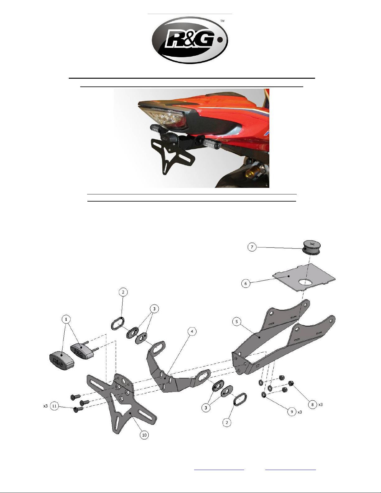
LEGEND
ITEM 1 = LICENCE PLATE ILLUMINATOR & SHROUD (LA0002) (x1).
ITEM 2 = OEM INDICATOR ADAPTOR (I0050) (x2).
ITEM 3 = MINI INDICATOR ADAPTOR (I0049) (x4).
ITEM 4 = INDICATOR BRACKET (TB0220 Part 4) (x1).
ITEM 5 = MOUNTING BRACKET (TB0220 Part 1) (x1).
ITEM 6 = COVER (TB0220 Part 2) (x1).
ITEM 7 = RUBBER BUNG (RB0002) (x1).
ITEM 8 = M5 NYLOC NUTS (x3).
ITEM 9 = M5 WASHERS (x3).
ITEM 10 = LICENCE PLATE BRACKET (TB0220 Part 3) (x1).
ITEM 11 = M5 x 16mm LONG COUNTERSUNK BOLTS (x3).
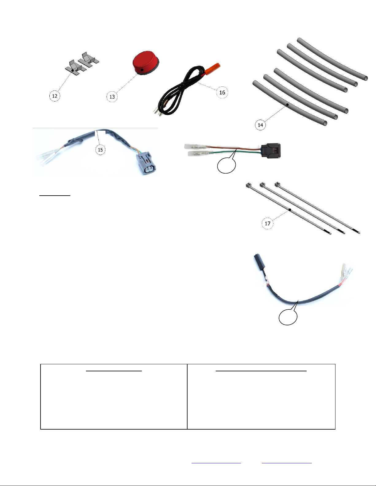
ITEM 12 = SELF-ADHESIVE CABLE CLIPS (x2).
ITEM 13 = REFLECTOR (x1).
ITEM 14 = 150mm LENGTH OF HEATSHRINK (x6).
ITEM 15 = LICENCE PLATE ILLUMINATOR CONNECTOR (CON0049) (x1).
ITEM 16 = MINI INDICATOR CONNECTOR (CON0009) (x2).
ITEM 17 = 2.5mm CABLE TIES (x3).
ITEM 18 = CON0053 Licence plate connector (2020- models) (x1)
ITEM 19 = CON0050 Indicator connector (2020- Models) (x2)
•Set of metric Allen keys.
•6, 8, 10 & 12mm spanners and sockets.
•Phillips screwdriver.
•Cable cutters
M4 BOLT = 8Nm
M5 BOLT = 12Nm
M6 BOLT = 15Nm
M8 BOLT = 20Nm
M10 BOLT = 40Nm
M12 BOLT = 40Nm