R&G RGH0001BK User manual

R&G Racing
Unit 1, Shelley’s Lane, East Worldham, Alton, Hampshire, GU34 3AQ
Tel: +44 (0)1420 89007 Fax: +44 (0)1420 87301 www.rg-racing.com Email: info@rg-racing.com
FITTING INSTRUCTIONS FOR RGH0001BK REAR WHEEL HUGGER
HONDA VFR 1200
THIS KIT CONTAINS THE ITEMS PICTURED AND LABELLED BELOW.
DO NOT PROCEED UNTIL YOU ARE SURE ALL PARTS ARE PRESENT.
Please note that the way the kit is packed does not necessarily represent the way of
mounting to the bike
THE PARTS SHOWN MAY BE REPRESENTATIVE ONLY (FOR CLARITY OF INSTRUCTIONS ONLY)
1
10
9
8
7
6
5
4
3
6
11

R&G Racing
Unit 1, Shelley’s Lane, East Worldham, Alton, Hampshire, GU34 3AQ
Tel: +44 (0)1420 89007 Fax: +44 (0)1420 87301 www.rg-racing.com Email: info@rg-racing.com
LEGEND
ITEM 1 = HUGGER (HUG0001) (x1).
ITEM 3 = M6 D-SHAPED WASHER (x1).
ITEM 4 = BOOT GUARD SPACER (S0380) (x1).
ITEM 5 = STICKY PADS (x5).
ITEM 6 = M6x20mm LONG BUTTON HEAD BOLTS (x3).
ITEM 7 = M6x25mm O/DIA WASHERS (x2).
ITEM 8 = FLAT SIDED SPACER (S0385) (x1).
ITEM 9 = SPACER (S0386) (x1).
ITEM 10 = CLEARANCE CHECKING BLOCK (x1).
ITEM 11 = ANTI VIBRATION PLATE (SMW0006) (x1).
TOOLS REQUIRED
SET OF METRIC ALLEN KEYS TO INCLUDE 4mm A/F.
19mm SOCKET AND WRENCH.
TORQUE WRENCH (108Nm AND 17Nm).
12mm SOCKET AND WRENCH.
12mm A/F SPANNER.
FITTING INSTRUCTIONS
If a centre stand is fitted, continue with wheel removal as described below. If a centre stand is not fitted,
we recommend fitting by a qualified motorcycle mechanic.
Lift motorcycle onto centre stand.
Remove exhaust mounting bolt from rear pillion footrest in position shown in picture 1.
PICTURE 1 PICTURE 2
Slacken the exhaust band bolt in position shown in picture 2.
Support the exhaust and gently ease exhaust away from wheel until stopper contacts the frame.
Remove the wheel nuts.
Gently ease wheel out between exhaust and wheel nut studs.

R&G Racing
Unit 1, Shelley’s Lane, East Worldham, Alton, Hampshire, GU34 3AQ
Tel: +44 (0)1420 89007 Fax: +44 (0)1420 87301 www.rg-racing.com Email: info@rg-racing.com
PICTURE 3 PICTURE 4
Remove the two plastic grommets from holes in position shown in picture 3.
Remove original bolt from position shown in picture 4.
Place spacer from kit (ITEM 4, S0380) into recess in position shown in picture 4.
Place the two spacers (ITEMS 8 & 9, S0385 & S0386) into slots in the hugger (ITEM 1,
HUG0001) a small amount of blue tack or similar will hold them in place whilst fitting (as shown
in picture 5).
If not already fitted stick the mounting pads (ITEM 5) to boot guard section of hugger as shown in
picture 6.
PICTURE 5 PICTURE 6
PICTURE 7 PICTURE 8
Offer the hugger into swing-arm and align holes in hugger with the tapped holes in swing-arm.

R&G Racing
Unit 1, Shelley’s Lane, East Worldham, Alton, Hampshire, GU34 3AQ
Tel: +44 (0)1420 89007 Fax: +44 (0)1420 87301 www.rg-racing.com Email: info@rg-racing.com
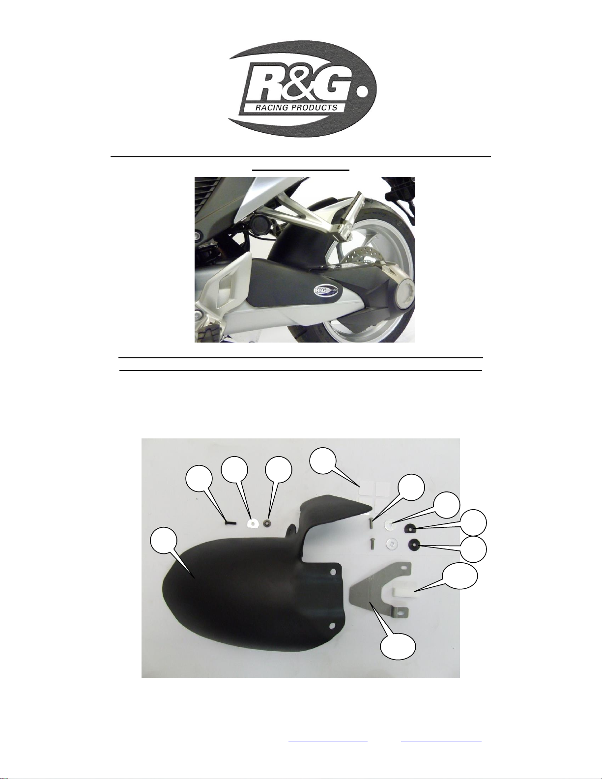
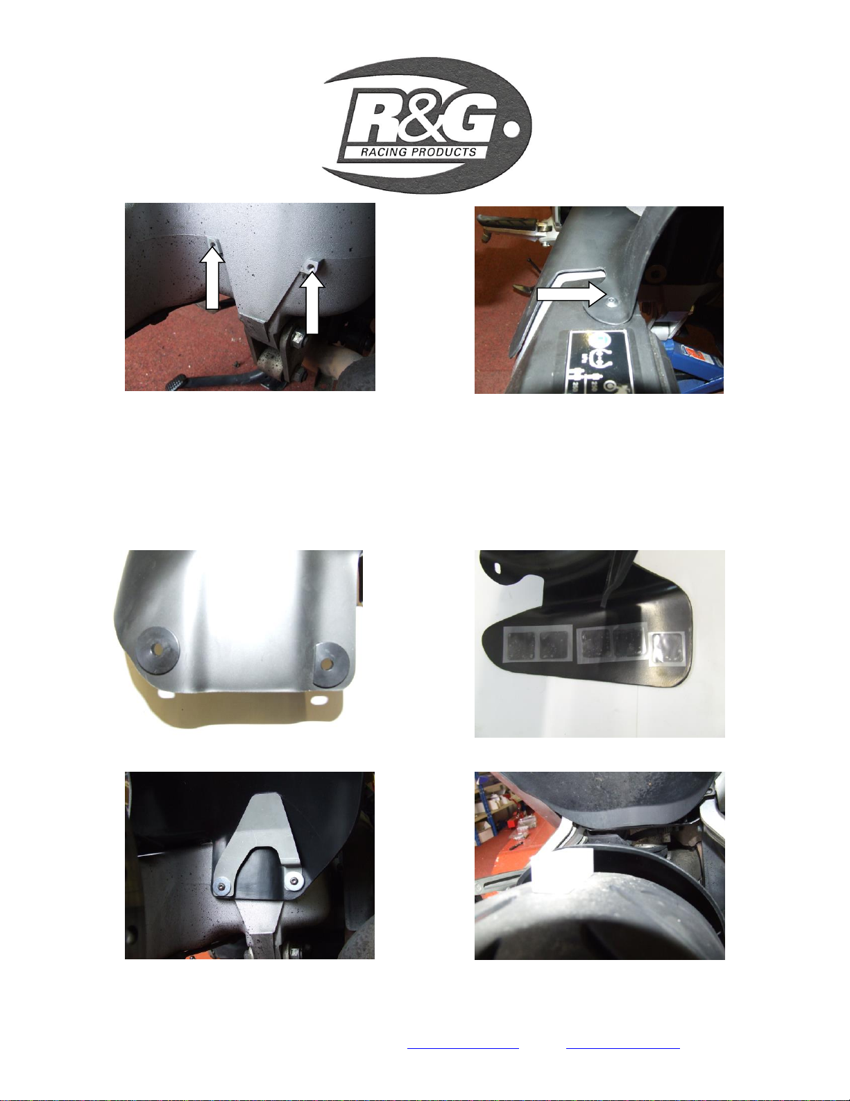
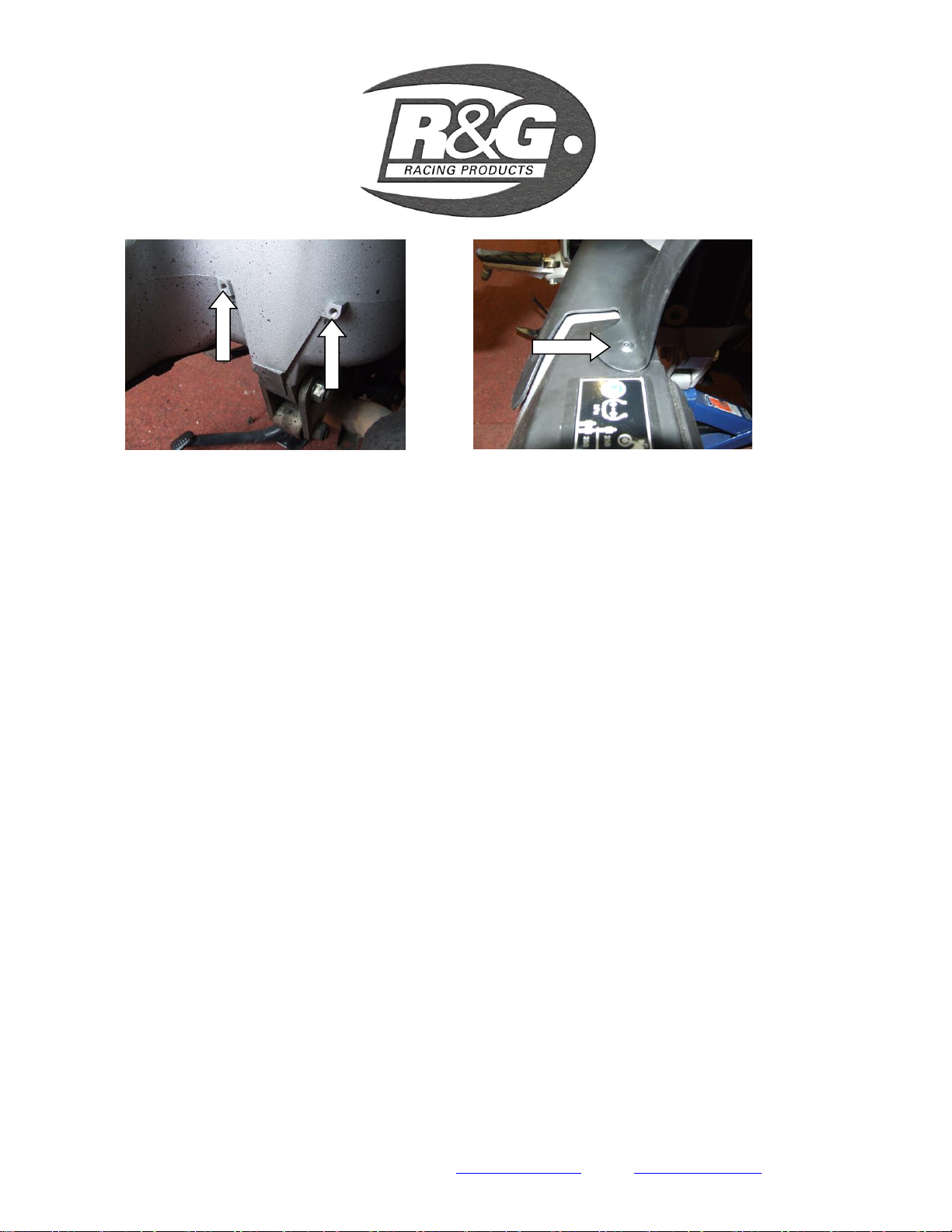
Offer the anti vibration plate (ITEM 11, SMW0006) into position as shown in picture 7, place the
two M6 washers (ITEMS 7) onto the two silver coloured button head bolts and clamp the
assembly in place. Do not tighten at this stage.
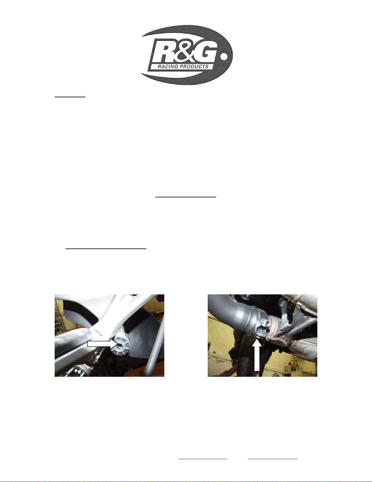
Place the D-shaped washer (ITEM 3) onto the black M6 bolt (ITEM 6) and engage thread in top of
swingarm as shown in picture 4. Do not tighten at this stage.
Slightly tighten all of the bolts so that the assembly is moveable but not loose.
Refit and tighten the rear wheel.
Position the spacer block included in kit on centre-line of tyre.
Move the hugger so the white spacer block just slides between hugger and tyre (PLEASE NOTE
A MINIMUM OF 14mm RADIAL CLEARANCE IS REQUIRED) (as shown in picture 8),
whilst ensuring the sides of the hugger are equally spaced from the edges of the tyre as shown in
picture 8.
Using a 4mm allen key tighten the two lower bolts.
Tighten the upper bolt to secure hugger in place (do not over-tighten).
Ensure the hugger has not moved while tightening
Gently ease boot guard portion of the hugger away from swing-arm and peel remaining protective
film from the adhesive tape, and press firmly into position.
Ensure wheel is tightened to 108Nm torque.
Reposition exhaust and secure using original nut, bolt and washers.
Retighten exhaust band bolt to 17Nm.
IMPORTANT: WHEN FITTING THE HUGGER, IT MUST BE POSITIONED AS
DESCRIBED ABOVE SO THAT THE HUGGER WILL NOT CONTACT THE REAR
WHEEL. IT IS YOUR RESPONSIBILITY TO CHECK FOR THIS POSSIBILITY AND TAKE
AVOIDING ACTION. FAILURE TO CHECK THIS COULD RESULT IN SERIOUS INJURY.
CONSUMER NOTICE
The catalogue description and any exhibition of samples are only broad indications of the Products and R&G may make design
changes which do not diminish their performance or visual appeal and supplying them in such state shall conform to the order. The
Buyer acknowledges no representation or warranty (other than as to title) has been given or will apply to the Products other than those
in R&G’s order or confirmation and the Buyer confirms it has chosen the Products as being of merchantable quality and suitable for
its particular purposes. Where R&G fits the Products or undertakes other services it shall exercise reasonable skill and care and rectify
any fault free of charge unless the workmanship has been disturbed. The Buyer is responsible for ensuring that the warranty on the
motorcycle is not affected by the fitting of the Products. On return of any defective Products R&G shall at its option either supply a
replacement or refund the purchase money but shall not be liable if the Products have been modified or used or maintained otherwise
than in accordance with R&G’s or manufacturer’s instructions and good engineering practice or if the defect arises from accident or
neglect. Other than identified above and subject to R&G not limiting its liability for causing death and personal injury, it shall not be
liable for indirect or consequential loss and otherwise its liability shall be limited to the amounts paid by the Buyer for the Products or
the fitting or service concerned. These terms do not affect the Buyer’s statutory rights.
R&G RACING RETURNS POLICY (NON-FAULTY GOODS)
Returns must be pre-authorised (if not pre-authorised the return will be rejected). Goods may only be returned direct to us if they were
purchased direct from us (customer must prove if necessary). Otherwise to be returned to original vendor. Goods must be in re-
sellable condition, in the opinion of R&G Racing. All returns are subject to a 25% restocking and handling fee (25% of the gross value
exc. P&P –at the prevailing price at time of purchase). The customer must pay any and all carriage charges. No returns of
discontinued products, unless within 14 days of purchase. This policy does not affect your statutory rights and does not refer to faulty
goods.

R&G Racing
Unit 1, Shelley’s Lane, East Worldham, Alton, Hampshire, GU34 3AQ
Tel: +44 (0)1420 89007 Fax: +44 (0)1420 87301 www.rg-racing.com Email: info@rg-racing.com
FRANCE
INSTRUCTIONS DE MONTAGE DU GARDE BOUE
RGH0001BK HONDA VFR 1200
VERIFIER QUE TOUTES LES PIECES MONTREES SUR LES PHOTOS SONT BIEN PRESENTES DANS LE KIT.
Le kit doit contenir également une entretoise blanche (non présentée sur les photos).
NOTE:
LE SENS DONT LE COLIS A ETAIT EMBALLE N’EST PAS IDENTIQUE AU SENS DE MONTAGE SUR LA MOTO ET CERTAINES PARTIES
MONTREES PEUVENT AVOIR PEUVENT ETRE UNIQUEMENT REPRESENTATIVES,POUR LA CLARTE DES INSTRUCTIONS.
LEGENDE
Article 1 = GARDE BOUE (HUG0001) (x1).
Article 3 = M6 D-RONDELLE (x1).
Article 4 = ENTRETOISE DU GARDE BOUE (S0380) (x1).
Article 5 = AUTO COLLANTS (x5).
Article 6 = M6x20mm LONGS BOULONS A TETE RONDE (x3).
Article 7 = M6x25mm O/DIA RONDELLES (x2).
Article 8 = ENTRETOISE PLATE (S0385) (x1).
Article 9 = ENTRETOISE (S0386) (x1).
Article 10 = BLOC DE CONTROLE DE JEU (x1).
Article 11 = PALQUE ANTI VIBRATION (SMW0006) (x1).
OUTILS NECESSAIRES:
Jeu de clé Allen (inclue une clé de 4 mm A/F).
Clef de 19mm
Clé dynamométrique (108Nm et 17Nm).
Clé plate de 12mm.
Clef à douille 12mm.
INSTRUCTIONS DE MONTAGE
Si la moto est pourvue d’une béquille centrale, continuez le montage. S’il n’y a pas de béquille centrale,
nous vous recommandons qu’un mécanicien qualifié puisse en positionner une durant le montage.
Lever la moto sur la béquille centrale.
Enlever la vis du silencieux d’échappement située sur le repose pied passager (photo 1).
Détendre le collier de serrage du silencieux (photo 2).
Tenir le silencieux et le pousser vers l’extérieur jusqu'à ce qu’il soit en contact avec le cadre.
Enlever les écrous de la roue.
Retirer la roue

R&G Racing
Unit 1, Shelley’s Lane, East Worldham, Alton, Hampshire, GU34 3AQ
Tel: +44 (0)1420 89007 Fax: +44 (0)1420 87301 www.rg-racing.com Email: info@rg-racing.com
Enlever les deux clips en plastique des trous (voir les positions sur la photo en dessus à gauche).
Enlever la vis d’origine située sur la photo 4.
Placer la rondelle du kit (article 4, S0380) dans le trou (photo 4).
Placer les 2 entretoises (article 8 et 9, S0385 et S0386) dans les trous (article 1, HUG0001) un
petit morceau de sellerie bleu les tiendra ne place durant le montage (photo 5).
Si ce n'est pas déjà fait, coller les patins de montage (article 5) pour démarrer la section garde
boue (image 6)
Applique la protection au bras oscillant en bras oscillant et aligner les trous avec ceux qui sont
taraudés dans le bras oscillant.
Mettre la plaque anti-vibrations (article 11, SMW0006) en position, comme indiqué dans l'image
7, placer les deux rondelles M6 (ARTICLE 7) sur les deux boulons à tête argentée et appliquer
l’ensemble en place. Ne serrez pas à ce stade.
Placer la rondelle en forme de D (article 3) sur le boulon M6 noir (article 6) et d'engager filet en
haut du bras oscillant, comme indiqué dans l'image 4. Ne serrez pas à ce stade.
Serrer les deux vis du bas, afin que le garde boue soit maintenu en position.
Remonter la roue.
Positionner l’entretoise (livrée dans le kit) dans l’axe du pneu.
Bouger le garde boue de manière à ce que l’entretoise blanche glisse entre le pneu et le garde
boue. (Merci de noter qu’un dégagement radial de 14 mm est nécessaire) assurez vous que les
côtés du ras de roue soit espacé de manière égale des bords du pneu (photo 8).
A l’aide d’une clé Allen de 4 mm, serrer les deux vis inférieures.
Serrer la vis supérieure pour conserver le garde boue en place (ne pas serrer trop fort).
Assurez-vous que la roue est serrée au couple de 108Nm.
Repositionner le silencieux d’échappement et fixer le en utilisant les entretoises, vis et écrou
d’origine.
Resserrer le collier de serrage du silencieux 17Nm.
IMPORTANT: VOUS DEVEZ PLACER LE GARDE BOUE COMME DÉCRIT CI-DESSUS. POUR QUE LE
RAS DE ROUE NE SOIT PAS EN CONTACT AVEC LA ROUE ARRIÈRE. IL EST DE VOTRE
RESPONSABILITE DE VÉRIFIER CETTE POSSIBILITÉ ET DE PRENDRE LES MESURES NECESSAIRES
POUR QUE CELA NE SE PRODUISE PAS.
NE PAS EFFECTUER DE VERIFICATION POURRAIT ABOUTIR À DES BLESSURES SÉRIEUSES.
Table of contents
Languages:
Other R&G Motorcycle Accessories manuals
Popular Motorcycle Accessories manuals by other brands

O'Neal
O'Neal Commander user manual

KTM Power Parts
KTM Power Parts TOP-CASE 46 Mounting instructions

hepco & becker
hepco & becker Easyrack quick guide

Dynojet
Dynojet Power commander V installation instructions

Kuryakyn
Kuryakyn 5455 installation instructions

J&M Corporation
J&M Corporation HSBL-145X7-XXR installation instructions