R&G LP0273 User manual

R&G Racing
Unit 1, Shelleys Lane, East Worldham, Alton, Hampshire GU34 3AQ.
Tel: +44 (0)1420 89007 Fax +44 (0)1420 87301 www.rg-racing.com Email: info@rg-racing.com
PAGE 1 OF 22 LP0273
Picture A Picture B
Please note that the way the kit is packed does not necessarily represent the way
of mounting to the bike.
In the event of rubber washers being used to hold components onto bolts,
these rubber washers can be thrown away.
THIS KIT CONTAINS THE ITEMS PICTURED AND LABELLED OVER PAGE.
SOME PARTS MAY BE SHOWN FOR CLARITY OF INSTRUCTIONS ONLY.
DONOT PROCEED UNTIL YOU ARE SURE ALL PARTS ARE PRESENT.
PLEASE READ ALL INSTRUCTIONS BEFORE PROCEEDING.
IF IN ANY DOUBT WHEN FITTING OUR PRODUCTS, CONSULT ONE OF OUR DEAL-
ERS OR HAVE FITTED BY A QUALIFIED TECHNICIAN.
Fitting Instructions For LP0273 TAIL TIDY
HONDA CB500F 2019-
DIGITAL COPIES OF THESE INSTRUCTIONS ARE AVAILABLE FROM
www.rg-racing.com

PAGE 2 OF 22 LP0273
R&G Racing
Unit 1, Shelleys Lane, East Worldham, Alton, Hampshire GU34 3AQ.
Tel: +44 (0)1420 89007 Fax +44 (0)1420 87301 www.rg-racing.com Email: info@rg-racing.com
TOOLS REQUIRED
• Set of metric Allen keys to include 4 & 5mm
A/F size.
• 6, 8, 10 & 13mm spanners or sockets.
• Phillips screwdriver.
• Cable cutters.
GENERAL TORQUE SETTINGS
M4 BOLT = 8Nm
M5 BOLT = 12Nm
M6 BOLT = 15Nm
M8 BOLT = 20Nm
M10 BOLT = 40Nm
M12 BOLT = 40Nm
ITEM
NO. DESCRIPTION QTY
ITEM 1 LA0002 No. PLATE LIGHT inc 1
ITEM 2 LICENCE PLATE BRACKET (TB0198 Part 2) 1
ITEM 3 INDICATOR ADAPTORS (I0031) 4
ITEM 4 INDICATOR SPACERS (I0032)2
ITEM 5 M6 WASHER 8
ITEM 6 M6 x 6mm LONG BUTTON HEAD BOLTS 4
ITEM 7 M6 x 30mm LONG BUTTON HEAD BOLTS 4
ITEM 8 MOUNTING BRACKET (TB0198 Part 1) 1
ITEM 9 SPACER PLATE (TB0198 Part 3) 2
ITEM 10 M6 NYLOC NUTS 4
ITEM 11 2.5mm CABLE TIES 3
ITEM 12 150mm LENGTH OF HEATSHRINK 3
ITEM 13 REFLECTOR 1
ITEM 14 SELF-ADHESIVE CABLE CLIPS 2
ITEM 15 No. PLATE ILLUMINATOR / INDICATOR CONNECTORS
(CON0009) 3
LEGEND

R&G Racing
Unit 1, Shelleys Lane, East Worldham, Alton, Hampshire GU34 3AQ.
Tel: +44 (0)1420 89007 Fax +44 (0)1420 87301 www.rg-racing.com Email: info@rg-racing.com
PAGE 3 OF 22 LP0273
ASSEMBLY DIAGRAM

PAGE 4 OF 22 LP0273
R&G Racing
Unit 1, Shelleys Lane, East Worldham, Alton, Hampshire GU34 3AQ.
Tel: +44 (0)1420 89007 Fax +44 (0)1420 87301 www.rg-racing.com Email: info@rg-racing.com
Picture 1 Picture 2
Picture 6
Picture 3
Picture 5
Picture 4

R&G Racing
Unit 1, Shelleys Lane, East Worldham, Alton, Hampshire GU34 3AQ.
Tel: +44 (0)1420 89007 Fax +44 (0)1420 87301 www.rg-racing.com Email: info@rg-racing.com
PAGE 5 OF 22 LP0273
Picture 8
Picture 12Picture 11
Picture 9 Picture 10
Picture 7

PAGE 6 OF 22 LP0273
R&G Racing
Unit 1, Shelleys Lane, East Worldham, Alton, Hampshire GU34 3AQ.
Tel: +44 (0)1420 89007 Fax +44 (0)1420 87301 www.rg-racing.com Email: info@rg-racing.com
Picture 13
Picture 18Picture 17
Picture 16Picture 15
Picture 14

R&G Racing
Unit 1, Shelleys Lane, East Worldham, Alton, Hampshire GU34 3AQ.
Tel: +44 (0)1420 89007 Fax +44 (0)1420 87301 www.rg-racing.com Email: info@rg-racing.com
PAGE 7 OF 22 LP0273
Picture 19 Picture 20
Picture 22Picture 21

PAGE 8 OF 22 LP0273
R&G Racing
Unit 1, Shelleys Lane, East Worldham, Alton, Hampshire GU34 3AQ.
Tel: +44 (0)1420 89007 Fax +44 (0)1420 87301 www.rg-racing.com Email: info@rg-racing.com
FITTING INSTRUCTIONS
• To fit the R&G tail tidy, remove the pillion seat using the key.
• Underneath the pillion seat, disconnect the orange, blue and white connectors for the li-
cence plate illuminator light and two indicators, as shown in picture 1.
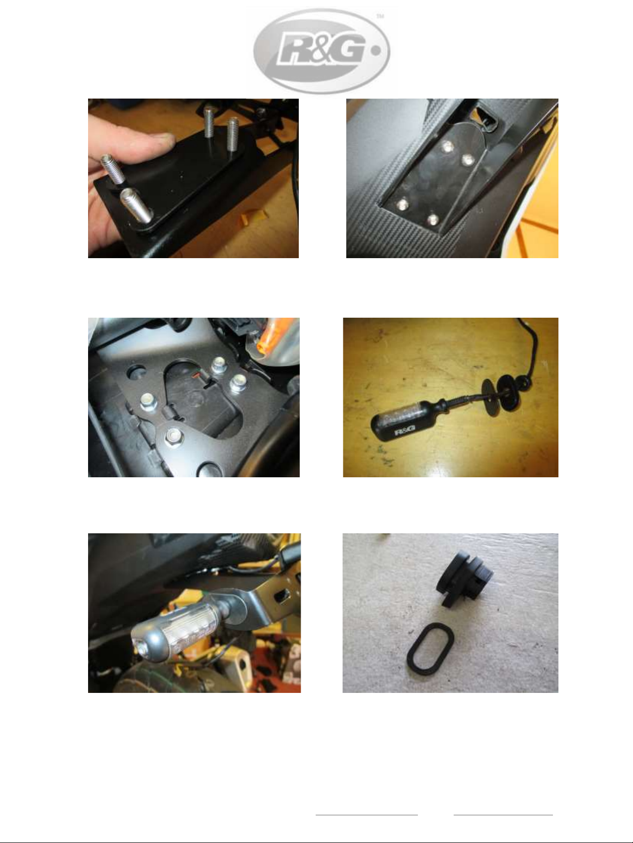
• Remove the four bolts that mount the OEM licence plate hanger in place and support the
licence plate whilst feeding the wires out and removing from the bike, as shown in pictures 2,
3 & 4.
• Remove the plastic undertray from the OEM licence plate hanger by removing the two
bolts that are positioned as arrowed in picture 5.
• Remove the domed nut on either indicator, as arrowed in picture 6, and remove the metal
plate on the inside before feeding the indicator and wiring out through the hole, as shown in
picture 7.
• Repeat the above procedure for the remaining indicator.
• With the indicator removed, the rubber mount now needs to be pulled from the licence
plate hanger, as shown in picture 8.
The indicator and mounting parts removed are shown in picture 9, along with the domed nut.
• Take the R&G mounting bracket (item 8 –TB0198 Part 1) and fit it to the R&G licence
plate bracket (item 2 –TB0198 Part 2) using the four M6 x 6mm button head bolts (item 6)
and four M6 washers (item 5), as shown in pictures 10 & 11, by fitting the bolts from behind
as shown.
• Take the R&G licence plate illuminator (item 1 –LA0002) and fit the shroud using a small
amount of superglue, before fitting it to the licence plate bracket, as shown in picture 12, be-
fore fitting the washer and nuts on the rear and tightening. Fit one length of heatshrink to the
wires for protection.
• Take both spacer plates (item 9 –TB0198 Part 3) and offer them into place on the top
mounting face of the tail tidy assembly, before locating the four M6 x 30mm long button head
bolts (item 7) through the mounting bracket and then through the four holes on the spacer
plates, as shown in picture 13.
• Offer this assembly up to the underside of the tail and locate the four bolts through the
four mounting holes in the bodywork/subframe, before fitting one M6 washer (item 5) and
one M6 nyloc nut (item 10) to the exposed thread on each bolt, as shown in picture 15. Tight-
If fitting R&G Mini Indicators
• To fit the R&G Mini Indicators, fit one length of heat shrink to the wires of each indicator.
• Position two indicator adaptors (item 3 –I0031) onto the wiring of each indicator, ensuring
the sides facing each other have the raised centre profile, before fitting the flanged nut sup-
plied, as shown in picture 16.
Fit either indicator through the large slot on the either side of the tail tidy, locating the indica-
tor adaptors either side of the metal bracket, before fitting the nut onto the exposed thread

R&G Racing
Unit 1, Shelleys Lane, East Worldham, Alton, Hampshire GU34 3AQ.
Tel: +44 (0)1420 89007 Fax +44 (0)1420 87301 www.rg-racing.com Email: info@rg-racing.com
PAGE 9 OF 22 LP0273
If fitting OEM Indicators
• Fit one indicator spacer (item 4 –I0032) to both rubber indicator mounts, as shown in
picture 18, before fitting into the large slot on either side of the tail tidy, ensuring the shal-
lower side of the rubber mount is on the inside.
• Take the OEM indicator, and feed the wiring through the hole in the rubber mount, before
sliding the metal bracket onto the wiring in the same way as it was removed from the bike,
as shown in picture 19.
• Once fitted, fit the domed nut and tighten to secure the indicator in place, as shown in
picture 20.
• Repeat the above process for both indicators.
• With the indicators of choice fitted, feed the wiring through the two holes on either spar of
the tail tidy, as shown in pictures 21 & 22 and feed the indicator and licence plate illuminator
wiring up through the exposed hole on the underside of the tail bodywork. Use the cable ties
and self-adhesive cable clips supplied to route the wiring neatly.
• Take the three connectors supplied (item 15 –CON0009) and connect one from the li-
cence plate illuminator to the OEM connector (if illumination fails, reverse the bullet connect-
ors).
• Fit the remaining two connectors to the indicator wiring as below:
• If fitting R&G Aero Indicators with LED’s the yellow wire on the Aero Indicators connects
with the black wire on the CON0009 and the black wire on the Mini Indicators connects with
the red wire on the CON0009. 1x set of RGR0001 & RGR0002 resistors (mounted inline)
(available separately) are required to achieve the correct flash rate.
• If fitting R&G Mini Indicators with bulbs, the black wire on the Mini Indicators connects
with the black wire on the CON0009 and the black/white wire on the Mini Indicators connects
with the red wire on the CON0009.
• If fitting R&G LED Mini Indicators, the black wire on the Mini Indicators connects with the
red wire on the CON0009 and the black/white wire on the Mini Indicators connects with the
black wire on the CON0009. 1x set of RGR0001 & RGR0002 resistors (mounted inline)
(available separately) are required to achieve the correct flash rate.
• Connect each connector up to the OEM wiring and check for the correct operation of all
lights.
• Neatly secure the wiring within the tail unit using the cable ties supplied.
Re-fit the pillion seat.
• Ensure the tail tidy is securely mounted and all bolts are fully tightened.
• Re-fit the licence plate (it may require drilling).
ISSUE 2 20/09/2019 (FB)

PAGE 10 OF 22 LP0273
R&G Racing
Unit 1, Shelleys Lane, East Worldham, Alton, Hampshire GU34 3AQ.
Tel: +44 (0)1420 89007 Fax +44 (0)1420 87301 www.rg-racing.com Email: info@rg-racing.com
IMPORTANT: IF YOU MOUNT A LARGE PLATE AND PLACE IT AT THE LOWER OF THE
PLATE BRACKET, IT IS POSSIBLE THAT THE PLATE WILL TOUCH THE REAR TYRE WHEN
RIDING OVER A BIG BUMP ON A ROUGH ROAD. IT IS YOUR RESPONSIBILITY TO
VERIFY THAT THIS CAN NOT OCCUR. NOT PERFORMING THIS CHECK CAN LEAD TO
DAMAGE TO THE MOTORCYCLE AND ITS RIDE OR PASSENGER.
CONSUMER NOTICE
The catalogue description and any exhibition of samples are only broad indications of the Products and R&G may
make design changes which do not diminish their performance or visual appeal and supplying them in such state
shall conform to the order. The Buyer acknowledges no representation or warranty (other than as to title) has been
given or will apply to the Products other than those in R&G’s order or confirmation and the Buyer confirms it has cho-
sen the Products as being of merchantable quality and suitable for its particular purposes. Where R&G fits the Prod-
ucts or undertakes other services it shall exercise reasonable skill and care and rectify any fault free of charge unless
the workmanship has been disturbed. The Buyer is responsible for ensuring that the warranty on the motorcycle is
not affected by the fitting of the Products. On return of any defective Products R&G shall at its option either supply a
replacement or refund the purchase money but shall not be liable if the Products have been modified or used or
maintained otherwise than in accordance with R&G’s or manufacturer’s instructions and good engineering practice or
if the defect arises from accident or neglect. Other than identified above and subject to R&G not limiting its liability
for causing death and personal injury, it shall not be liable for indirect or consequential loss and otherwise its liability
shall be limited to the amounts paid by the Buyer for the Products or the fitting or service concerned. These terms do
not affect the Buyer’s statutory rights.
R&G RACING RETURNS POLICY (NON-FAULTY GOODS)
Returns must be pre-authorised (if not pre-authorised the return will be rejected). Goods may only be returned direct
to us if they were purchased direct from us (customer must prove if necessary). Otherwise to be returned to original
vendor. Goods must be in re-sellable condition, in the opinion of R&G Racing. All returns are subject to a 25% re-
stocking and handling fee (25% of the gross value exc. P&P –at the prevailing price at time of purchase). The cus-
tomer must pay any and all carriage charges. No returns of discontinued products, unless within 14 days of pur-
chase. This policy does not affect your statutory rights and does not refer to faulty goods.

R&G Racing
Unit 1, Shelleys Lane, East Worldham, Alton, Hampshire GU34 3AQ.
Tel: +44 (0)1420 89007 Fax +44 (0)1420 87301 www.rg-racing.com Email: info@rg-racing.com
PAGE 11 OF 22 LP0273
Photo A Photo B
LAFAÇON DONT LE KIT EST EMBALLÉ NE CORRESPOND PAS FORCÉMENT ÀLA FAÇON DE MONTER
LES PIÈCES SUR LA MOTO .
NOTEZ QUE SI LES KITS SONT EMBALLÉS AVEC DES RONDELLES EN CAOUTCHOUC SERVANT À
TENIR LES COMPOSANTS, CES RONDELLES DOIVENT ÊTRE JETÉES.
LEKIT CONTIENT LES ARTICLES EN PHOTO ET ETIQUETTES SUR LA PAGE
LES PARTIES PRESENTÉES PEUVENT ETRE UNIQUEMENT REPRESENTATIVES POUR LA CLARTE DES INSTRUCTIONS
NEPAS PROCÉDER AU MONTAGE AVANT DE VOUS ÊTRES ASSURE QUE TOUTES LES PIECES SOIENT PRÉ-
SENTES.
SVP, LIRE L’ENSEMBLE DE LA NOTICE AVANT DE PROCÉDER AU MONTAGE.
EN CAS DE DOUTE LORS DU MONTAGE, CONSULTEZ UN DE NOS REVENDEURS, OU
FAITES EFFECTUER LE MONTAGE PAR UN TECHNHICIEN QUALIFIE.
NOTICE DE MONTAGE POUR LP0273 SUPPORT DE PLAQUE
HONDA CB500F 2019-
NOTICE DISPONIBLE AU TÉLÉCHARGEMENT SUR : WWW.RG-RACING.COM

PAGE 12 OF 22 LP0273
R&G Racing
Unit 1, Shelleys Lane, East Worldham, Alton, Hampshire GU34 3AQ.
Tel: +44 (0)1420 89007 Fax +44 (0)1420 87301 www.rg-racing.com Email: info@rg-racing.com
OUTILS REQUIS
• Clés Allen 4 & 5mm
• Clé à cliquet + douilles 6, 8, 10 & 13mm
• Tournevis cruciforme
• Coupe câble
VALEURS DE SERRAGE
M4 BOULON = 8Nm
M5 BOULON = 12Nm
M6 BOULON = 15Nm
M8 BOULON = 20Nm
M10 BOULON = 40Nm
M12 BOULON = 40Nm
ARTICLE
NO.
DESCRIPTION QTE
ARTICLE
1LA0002 No. FEU DE PLAQUE inc 1
ARTICLE
2SUPPORT DE PLAQUE (TB0198 Partie 2) 1
ARTICLE
3ADAPTATEUR DE CLIGNOTANT (I0031) 4
ARTICLE
4ENTRETOISES DE CLIGNOTANT (I0032)2
ARTICLE
5M6 RONDELLE 8
ARTICLE
6M6 x 6mm BOULONS 4
ARTICLE
7M6 x 30mm BOULONS 4
ARTICLE
8SUPPORT DE FIXATION (TB0198 Partie 1) 1
ARTICLE
9
PLAQUE D’ENTRETOISE (TB0198 Partie 3) 2
ARTICLE
10 M6 ECROUS 4
ARTICLE
11 2.5mm COLLIERS DE SERRAGE 3
ARTICLE
12 150mm MANCHON THERMO RETRACTABLE 3
ARTICLE
13 REFLECTEUR 1
ARTICLE
14 CLIPS AUTOCOLLANTS 2
ARTICLE
15 No. FEU DE PLAQUE / CONNECTEURS DE CLIGNOTANT
(CON0009)
3
LEGENDE

R&G Racing
Unit 1, Shelleys Lane, East Worldham, Alton, Hampshire GU34 3AQ.
Tel: +44 (0)1420 89007 Fax +44 (0)1420 87301 www.rg-racing.com Email: info@rg-racing.com
PAGE 13 OF 22 LP0273
SCHEMA DE MONTAGE

PAGE 14 OF 22 LP0273
R&G Racing
Unit 1, Shelleys Lane, East Worldham, Alton, Hampshire GU34 3AQ.
Tel: +44 (0)1420 89007 Fax +44 (0)1420 87301 www.rg-racing.com Email: info@rg-racing.com
NOTICE DE MONTAGE
• Pour monter le support de plaque R&G, retirez le siège passager à l'aide de la clé.
• Sous le siège passager, débranchez les connecteurs orange, bleu et blanc de feu de plaque d’immatricula-
tion et deux clignotants, comme indiqué sur la photo 1.
• Retirez les quatre boulons qui fixent le support de plaque d'immatriculation d’origine en place et
maintenez la plaque d'immatriculation tout en dévidant les câbles et en les retirant de la moto, comme indi-
qué sur les photos 2, 3 et 4.
• Retirez le passage de gaine en plastique du support de plaque d'immatriculation d’origine en retirant les
deux boulons placés comme indiqué sur la photo 5.
• Retirez l’écrou bombé de l’un des clignotants, comme indiqué sur la photo 6, et retirez la plaque métal-
lique à l’intérieur avant de faire passer le clignotant et le câblage à travers le trou, comme indiqué sur la pho-
to 7.
• Répétez la procédure ci-dessus pour le clignotant restant.
• Le clignotant étant retiré, vous devez maintenant retirer le support en caoutchouc du support de plaque
d'immatriculation, comme indiqué sur la photo 8.
• Le clignotant et les pièces de montage retirées sont illustrés sur la photo 9, avec l'écrou bombé.
• Prenez le support de fixation R&G (article 8 - TB0198 Partie 1) et fixez-le au support de plaque d'immatric-
ulation R&G (article 2 - TB0198 Partie 2) à l'aide des quatre boulons à tête ronde M6 x 6mm (article 6) et des
quatre rondelles M6 (article 5). ), comme indiqué sur les photos 10 et 11, en insérant les boulons par l’arrière,
comme indiqué.
• Prenez le feu de plaque d’immatriculation R&G (article 1 - LA0002) et montez la protection en utilisant un
peu de colle avant de le fixer sur le support de plaque d’immatriculation, comme indiqué sur la photo 12,
avant de serrer la rondelle et les écrous à l’arrière. Placez une longueur de thermo rétractable sur les fils pour
les protéger.
• Prenez les deux plaques d'entretoise (article 9 - TB0198, partie 3) et placez-les sur la face de montage
supérieure du support de plaque, avant de placer les quatre boulons à tête ronde M6 x 30 mm de long (article
7) à travers le support de montage, puis à travers les 4 trous des plaques d’entretoise, voir photo 13.
• Offrez cet assemblage au dessous du support, puis placez les quatre boulons dans les quatre trous de fixa-
Si vous montez les mini clignotants R&G
• Pour monter les mini-clignotants R&G, placez une longueur de thermo retractable sur les fils de chaque
clignotant.
• Positionnez deux adaptateurs de clignotant (article 3 –I0031) sur le câblage de chaque clignotant, en vous
assurant que les côtés se faisant face aient le profil central relevé, avant de fixer l'écrou à collerette fourni,
comme indiqué sur la photo 16.
• Insérer le clignotant dans la grande fente située de part et d’autre du support de plaque, en plaçant les
adaptateurs de clignotant sur de chaque côté du support métallique, avant de fixer l’écrou sur le filetage ap-

R&G Racing
Unit 1, Shelleys Lane, East Worldham, Alton, Hampshire GU34 3AQ.
Tel: +44 (0)1420 89007 Fax +44 (0)1420 87301 www.rg-racing.com Email: info@rg-racing.com
PAGE 15 OF 22 LP0273
Si vous montez les clignotants d’origine
Placer une entretoise de clignotant (article 4 - I0032) sur les deux supports en caoutchouc, comme in-
diqué sur la photo 18, avant de l'installer dans la grande fente de chaque côté du support de plaque, en
veillant à ce que le côté le moins profond du support en caoutchouc soit à l'intérieur.
• Prenez le clignotant d’origine et faites passer le câblage à travers le trou du support en caoutchouc,
avant de faire glisser le support en métal sur le câblage de la même manière qu'il a été retiré de la mo-
to, comme indiqué sur la photo 19.
• Une fois installé, fixez l’écrou bombé et serrez-le pour maintenir le clignotant en place, comme indi-
qué sur la photo 20.
• Répétez le processus ci-dessus pour les deux clignotants.
• Une fois les clignotants nstallés, faites passer le câblage dans les deux trous situés sur l’un des deux
longerons du support, comme indiqué sur les photos 21 et 22, et passez le câblage de clignotant et de
feu de plaque d’immatriculation dans le trou exposé situé sous le châssis. Utilisez les attaches de câble
et les colliers de câble auto-adhésifs fournis pour acheminer le câblage correctement.
• Prenez les trois connecteurs fournis (article 15 - CON0009) et connectez-en un du feu de plaque au
connecteur d’origine (si l’éclairage échoue, inversez les connecteurs).
• Branchez les deux connecteurs restants au câblage de clignotant comme indiqué ci-dessous:
• Si vous utilisez des clignotants R&G à LED, le fil jaune des clignotants se connecte au fil noir du
CON0009 et le fil noir des mini-clignotants au fil rouge du CON0009. 1x ensemble de résistances
RGR0001 et RGR0002 (montées en ligne) (disponibles séparément) est nécessaire pour obtenir le bon
niveau d’éclairage.
• Si vous utilisez des clignotants R&G à ampoule, le fil noir des mini-clignotants se connecte avec le fil
noir du CON0009 et le fil noir / blanc des mini-clignotants se connecte avec le fil rouge du CON0009.
• Si vous utilisez des mini clignotants R&G à LED, le fil noir des mini-clignotants se connecte avec le
fil rouge du CON0009 et le fil noir/blanc des mini-clignotants sur les mini clignotants se connecte au fil
noir du CON0009. 1x ensemble de résistances RGR0001 et RGR0002 (montées en ligne) (disponibles
séparément) est nécessaire pour obtenir le bon niveau d’éclairage.
• Connectez chaque connecteur au câblage d’origine et vérifiez le bon fonctionnement de tous les
feux.
• Fixez soigneusement le câblage dans l’unité arrière à l’aide des serre-câbles fournis.
• Remettre en place le siège passager
• Assurez-vous que le support soit bien monté et que tous les boulons soient bien serrés.
• Remettez en place la plaque d'immatriculation (cela peut nécessiter un perçage).
• Selon les lois locales, fixez le réflecteur fourni à un endroit approprié.
• Testez le feu de plaque d'immatriculation et tous les feux avant de prendre la route.

PAGE 16 OF 22 LP0273
R&G Racing
Unit 1, Shelleys Lane, East Worldham, Alton, Hampshire GU34 3AQ.
Tel: +44 (0)1420 89007 Fax +44 (0)1420 87301 www.rg-racing.com Email: info@rg-racing.com
• IMPORTANT : SI VOUS MONTEZ UNE PLAQUE DE GRANDE TAILLE ET QUE VOUS
LA PLACEZ AU PLUS BAS DU SUPPORT DE PLAQUE, IL EST POSSIBLE QUE LA
PLAQUE TOUCHE LA ROUE ARRIÈRE LORSQU’IL Y A UN POID IMPORTANT SUR LA
ROUE ARRIÈRE OU LORSQUE VOUS ROULEZ SUR UNE GROSSE BOSSE. IL EST DE
VOTRE RESPONSABILITÉ DE VÉRIFIER QUE CELA NE PUISSE SE PRODUIRE. NE
PAS EFFECTUER CETTE VÉRIFICATION PEUT CONDUIRE À DES DOMMAGES POUR
LA MOTO AINSI QUE POUR SON PILOTE OU SON PASSAGER.
CONSUMER NOTICE
The catalogue description and any exhibition of samples are only broad indications of the Products and R&G may
make design changes which do not diminish their performance or visual appeal and supplying them in such state
shall conform to the order. The Buyer acknowledges no representation or warranty (other than as to title) has been
given or will apply to the Products other than those in R&G’s order or confirmation and the Buyer confirms it has cho-
sen the Products as being of merchantable quality and suitable for its particular purposes. Where R&G fits the Prod-
ucts or undertakes other services it shall exercise reasonable skill and care and rectify any fault free of charge unless
the workmanship has been disturbed. The Buyer is responsible for ensuring that the warranty on the motorcycle is
not affected by the fitting of the Products. On return of any defective Products R&G shall at its option either supply a
replacement or refund the purchase money but shall not be liable if the Products have been modified or used or
maintained otherwise than in accordance with R&G’s or manufacturer’s instructions and good engineering practice or
if the defect arises from accident or neglect. Other than identified above and subject to R&G not limiting its liability
for causing death and personal injury, it shall not be liable for indirect or consequential loss and otherwise its liability
shall be limited to the amounts paid by the Buyer for the Products or the fitting or service concerned. These terms do
not affect the Buyer’s statutory rights.
R&G RACING RETURNS POLICY (NON-FAULTY GOODS)
Returns must be pre-authorised (if not pre-authorised the return will be rejected). Goods may only be returned direct
to us if they were purchased direct from us (customer must prove if necessary). Otherwise to be returned to original
vendor. Goods must be in re-sellable condition, in the opinion of R&G Racing. All returns are subject to a 25% re-
stocking and handling fee (25% of the gross value exc. P&P –at the prevailing price at time of purchase). The cus-
tomer must pay any and all carriage charges. No returns of discontinued products, unless within 14 days of pur-
chase. This policy does not affect your statutory rights and does not refer to faulty goods.
ISSUE 2 20/09/2019 (FB)

R&G Racing
Unit 1, Shelleys Lane, East Worldham, Alton, Hampshire GU34 3AQ.
Tel: +44 (0)1420 89007 Fax +44 (0)1420 87301 www.rg-racing.com Email: info@rg-racing.com
PAGE 17 OF 22 LP0273
Abbildung A Abbildung B
Montageanleitung für LP0273 KENNZEICHENHALTER
HONDA CB500F 2019-
ALLE KIT-TEILE SIND UNTEN ABGEBILDET UND GEKENNZEICHNET.
DIE ABGEBILDETEN TEILE DIENEN LEDIGLICH ZUR ERKLÄRUNG.
ÜBERPRÜFEN SIE ZUERST, DASS ALLE TEILE VORHANDEN SIND.
LESEN SIE DIE MONTAGEANLEITUNG KOMPLETT DURCH, BEVOR SIE ANFANGEN.
WENN SIE BEI DER MONTAGE DIESES PRODUKTES UNSICHER SIND , BITTE EINEN
UNSERER HÄNDLER KONTAKTIEREN ODER DAS KIT VON EINEM QUALIFIZIERTEN
ZWEIRAD-MECHANIKER MONTIEREN LASSEN.
DIE VERPACKUNG DER TEILE STELLT NICHT DIE REIHENFOLGE DER MONTAGE DAR.
HINWEIS FÜR KITS MIT PLASTIKUNTERLEGSCHEIBEN AN DEN SCHRAUBEN –
DIESE PLASTIK-UNTERLEGSCHEIBEN WERDEN NICHT FÜR DEN EINBAU BENÖTIGT!
EINE DIGITALE VERSION DIESER MONTAGEANLEITUNG KANN AUF
FOLGENDER SEITE HERUNTERGELADEN WERDEN:
WWW.RG-RACING.COM

PAGE 18 OF 22 LP0273
R&G Racing
Unit 1, Shelleys Lane, East Worldham, Alton, Hampshire GU34 3AQ.
Tel: +44 (0)1420 89007 Fax +44 (0)1420 87301 www.rg-racing.com Email: info@rg-racing.com
SIE BENÖTIGEN FOLGENDES WERKZEUG:
• Satz Inbusschlüssel inkl. Größe 4 & 5mm A/F
• 6, 8, 10 & 13mm Steckschlüssel oder
Schraubenschlüssel
• Kreuzschlitzschraubenzieher
• Seitenschneider
ALLGEM. ANZUGSDREHMOMENT
M4 SCHRAUBE = 8Nm
M5 SCHRAUBE = 12Nm
M6 SCHRAUBE = 15Nm
M8 SCHRAUBE = 20Nm
M10 SCHRAUBE = 40Nm
M12 SCHRAUBE = 40Nm
ARTIKEL
NR.
BESCHREIBUNG MENGE
ARTIKEL 1 LA0002 KENNZEICHENBELEUCHTUNG 1
ARTIKEL 2 KENNZEICHENHALTER (TB0198 Teil 2) 1
ARTIKEL 3 ADAPTER FÜR DIE BLINKER (I0031) 4
ARTIKEL 4 DISTANZHALTER FÜR DIE BLINKER (I0032)2
ARTIKEL 5 M6 UNTERLEGSCHEIBE 8
ARTIKEL 6 M6 x 6mm INBUSSCHRAUBE 4
ARTIKEL 7 M6 x 30mm INBUSSCHRAUBE 4
ARTIKEL 8 MONTAGEHALTERUNG (TB0198 Teil 1) 1
ARTIKEL 9 DISTANZPLATTE (TB0198 Teil 3) 2
ARTIKEL 10 M6 SELBSTSICHERNDE MUTTER 4
ARTIKEL 11 2,5mm KABELBINDER 3
ARTIKEL 12 150mm SCHRUMPFSCHLAUCH 3
ARTIKEL 13 RÜCKSTRAHLER 1
ARTIKEL 14 SELBSTSICHERNDE KABELCLIPS 2
ARTIKEL 15 VERBINDUNGEN FÜR KENNZEICHENBELEUCHTUNG UND
BLINKER (CON0009)
3
LIEFERUMFANG

R&G Racing
Unit 1, Shelleys Lane, East Worldham, Alton, Hampshire GU34 3AQ.
Tel: +44 (0)1420 89007 Fax +44 (0)1420 87301 www.rg-racing.com Email: info@rg-racing.com
PAGE 19 OF 22 LP0273
ZEICHNUNG ZUSAMMENBAU

PAGE 20 OF 22 LP0273
R&G Racing
Unit 1, Shelleys Lane, East Worldham, Alton, Hampshire GU34 3AQ.
Tel: +44 (0)1420 89007 Fax +44 (0)1420 87301 www.rg-racing.com Email: info@rg-racing.com
MONTAGEANELITUNG
• Um das R&G Kennzeichenhalter montieren zu können, entfernen Sie zuerst den Beifahrersitz
(der Schlüssel wird hierfür benötigt).
• Unter dem Beifahrersitz, die orange, blaue und weiße Steckverbinder für die
Kennzeichenbeleuchtung und die zwei Blinker trennen –siehe Abbildung 1.
• Entfernen Sie die vier Schrauben, die den original Kennzeichenhalter in Position befestigen, und
den Kennzeichenhalter stützen während Sie die Kabel rausziehen und vom Motorrad entfernen—
siehe Abbildungen 2, 3 & 4.
• Entfernen Sie die untere Abdeckung aus Kunststoff vom original Kennzeichenhalter, indem Sie
die zwei Schrauben entfernen, die in Abbildung 5 mit Pfeilen gekennzeichnet sind.
• Entfernen Sie die Hutmutter, die in Abbildung 6 abgebildet ist, und entfernen Sie die
Metallplatte an der Innenseite, bevor Sie die Blinkerkabel durch die Öffnung schieben—siehe
Abbildung 7.
• Diesen Vorgang mit dem übrigen Blinker wiederholen.
• Wenn die Blinker entfernt sind, muss die Gummihalterung vom Kennzeichenhalter weggezogen
werden - siehe Abbildung 8.
Die Blinker–und Montageteil sowie die Hutmutter, die entfernt wurden, sind in Abbildung 9
abgebildet.
• Nehmen Sie die R&G Montagehalterung (Artikel 8 –TB0198 Teil 1) und montieren Sie sie am
R&G Kennzeichenhalter (Artikel 2 –TB0198 Teil 2) mit den vier M6 x 6mm Inbusschrauben (Artikel
6) und vier M6 Unterlegscheiben (Artikel 5) wie in den Abbildungen 10 & 11 abgebildet. Die
Schrauben von hinten anbringen wie abgebildet.
• Mit etwas Sekundenkleber die Abdeckung für die Beleuchtung an der R&G
Kennzeichenbeleuchtung (Artikel 1 –LA0002) fixieren und die Einheit am Kennzeichenhalter
montieren wie in Abbildung 12 abgebildet—die Unterlegscheiben und Muttern hinten anbringen und
befestigen. Eine Länge Schrumpfschlauch an den Kabeln anbringen, um sie zu schützen.
• Nehmen Sie die Distanzplatten (Artikel 9 –TB0198 Teil 3) und positionieren Sie sie an der
oberen Montagefläche des Kennzeichenhalters. Die vier M6 x 30mm Inbusschrauben (Artikel 7)
durch die Montagehalterung dann durch die vier Öffnungen in den Distanzhalter einführen wie in
Abbildung 13 abgebildet.
• Die Einheit an der Unterseite des Hecks ansetzen und die vier Schrauben in die vier
Montageöffnungen im Hilfsrahmen/Verkleidungsteil einführen und jeweils eine M6 Unterlegscheibe
(Artikel 5) und eine M6 selbstsichernde Mutter (Artikel 10) am hervorstehenden Gewinde jeder
Schraube montieren wie in Abbildung 15 abgebildet. Alle vier schrauben gleichmäßig festziehen und
überprüfen, dass der Kennzeichenhalter sicher in Position befestigt ist.
Table of contents
Languages:
Other R&G Motorcycle Accessories manuals
Popular Motorcycle Accessories manuals by other brands

hepco & becker
hepco & becker 6607570 01 01 Mounting instructions

SW-Motech
SW-Motech KFT.05.876.70101/B Mounting instructions

RYCO MOTO
RYCO MOTO 2300 manual

LSL
LSL MANTIS-RS Mounting and safety instructions

Evotech Performance
Evotech Performance 13347 installation instructions

Clarke
Clarke HSF1 Operation & maintenance instructions

3M
3M L-705 Disassembly

SRC
SRC GPX-D150-02-01-SL Installation

Two Brothers Racing
Two Brothers Racing Juice Box 008-126C Installation & operation manual

hepco & becker
hepco & becker 5027552 00 22 Mounting instructions

SRC
SRC Royal Enfield Himalayan quick start guide

National Cycle
National Cycle N20331 manual