R&G LP0249BK User manual

LP0249
R&G
Unit 1, Shelley’s Lane, East Worldham, Alton, Hampshire, GU34 3AQ
Tel: +44 (0)1420 89007 Fax: +44 (0)1420 87301 www.rg-racing.com Email: info@rg-racing.com
1
Page | 1
FITTING INSTRUCTIONS FOR LP0249BK LICENCE PLATE BRACKET
Tail Tidy for Ducati Monster 821 '18-, 1200 (S) '17- & 1200R '18- for Ducati Monster
821 (2018)
THIS KIT CONTAINS THE ITEMS PICTURED AND LABELLED BELOW.
DO NOT PROCEED UNTIL YOU ARE SURE ALL PARTS ARE PRESENT.
Please note that the way the kit is packed does not necessarily represent the way of
mounting to the bike
THE PARTS SHOWN MAY BE REPRESENTATIVE ONLY (FOR CLARITY OF INSTRUCTIONS ONLY)
2
5
1
10
6
6
11
12
7
13
8
9
16
3
4
15
14

LP0249
R&G
Unit 1, Shelley’s Lane, East Worldham, Alton, Hampshire, GU34 3AQ
Tel: +44 (0)1420 89007 Fax: +44 (0)1420 87301 www.rg-racing.com Email: info@rg-racing.com
2
Page | 2
LEGEND
ITEM 1 = MAIN LICENCE PLATE MOUNTING BRACKET (TB0249BK-PART 1) (x1).
ITEM 2 = M8x30mm BUTTON HEAD BOLTS (x4).
ITEM 3 = MINI INDICATOR ADAPTORS (I0033) (x4).
ITEM 4 = MOUNTING SPACERS (S1121) (x4).
ITEM 5 = COVER (TB0224BK-PART 2) (x1).
ITEM 6 = M4x5mm BUTTON HEAD BOLTS (x2).
ITEM 7 = M4 WASHERS (x2).
ITEM 8 = LICENCE PLATE ILLUMINATOR ASSEMBLY (LA0002) (x1).
ITEM 9 = SELF ADHESIVE CABLE CLIPS (x4).
ITEM 10 = RUBBER EDGING SEAL (SRS002) (500mm LONG) (x1).
ITEM 11 = 180mm LENGTHS OF HEAT SHRINK (x3).
ITEM 12 = LARGE CABLE TIES (x4).
ITEM 13 = SMALL CABLE TIES (x8).
ITEM 14 = INDICATOR CONNECTORS (CON0004) (x2).
ITEM 15 = LICENCE PLATE ILLUMINATOR CONNECTOR (CON0014) (x1).
ITEM 16 = REFLECTOR (REFL 1) (x1).
ITEM 17 = INFILL PANEL (TB0249BK-PART 2) (x1).
Please note that in cases where kits are packed with rubber washers holding the components onto the bolt –the
rubber washers should be thrown away!
TOOLS REQUIRED
•Set of Metric Allen keys to include 3, 4 and 6mm A/F.
•Electrical pliers/crimps.
•Small amount of super glue.
17

LP0249
R&G
Unit 1, Shelley’s Lane, East Worldham, Alton, Hampshire, GU34 3AQ
Tel: +44 (0)1420 89007 Fax: +44 (0)1420 87301 www.rg-racing.com Email: info@rg-racing.com
6
Page | 6
PICTURE 16 PICTURE 17
PICTURE 18
FITTING INSTRUCTIONS
•Remove the seat using the keys.
•Remove the five bolts arrowed in pictures 1 and 2.
•Remove the plastic cable cover/indicator clamp plate.
•Remove the four bolts arrowed in picture 3.
•Carefully lower the original licence plate bracket as shown in picture 4.
•Disconnect the three wiring plug sockets for the licence plate illuminator and indicators as
arrowed in picture 5 (you will have to cut the several cable ties).
•Remove the four metal spacers as shown in picture 6.
•Remove the four rubber mounting bushes as shown in picture 7.
•Fit the four rubber mounting bushes to the new licence plate bracket (item 1) as shown in
picture 8.
•Fit the four metal spacers into the four rubber mounting bushes already fitted to the new
licence plate bracket (item 1) as shown in picture 9.
•Fit the four new mounting spacers (item 4) over the original metal spacers as shown in
picture 10 (a small amount of adhesive may be used to keep these spacers in position).
•Cut the rubber edging strip into suitable lengths and stick in position to the cover (item 5)
and the new licence plate bracket (item 1) as arrowed in pictures 11 and 12.
•Fit the new licence plate illuminator (item 8) to the new licence plate bracket (item 1) as
shown in pictures 13 and 14 (please use the provided heat shrink (item 11) to protect the
wiring).
•PLEASE NOTE YOU WILL NEED TO GLUE THE LIGHT SHROUD TO THE
LED LICENCE PLATE ILLUMINATOR USING SUPER GLUE.
If reusing the original indicators
•Cut the cable ties securing the wiring and remove the indicator (please note which side it
came off).
•Repeat the above to remove the other indicator (please note the relevant sides).
•Gently squeeze the indicator stem and push through the shape aperture in the new licence
plate bracket (item 1) as shown in picture 15 (a small amount of silicon grease or liquid
detergent helps in this process
•Fit the indicators to the new licence plate bracket (item 1) as they were mounted
originally (ensure they are fitted on the correct sides).
•Route the wiring as original

LP0249
R&G
Unit 1, Shelley’s Lane, East Worldham, Alton, Hampshire, GU34 3AQ
Tel: +44 (0)1420 89007 Fax: +44 (0)1420 87301 www.rg-racing.com Email: info@rg-racing.com
7
Page | 7
•Reconnect the indicators to the original wiring plug sockets.
•It is a good idea to check the operation of the licence plate illuminator and indicators at
this stage (if the licence plate illuminator fails to light please swap the bullet connectors
over).
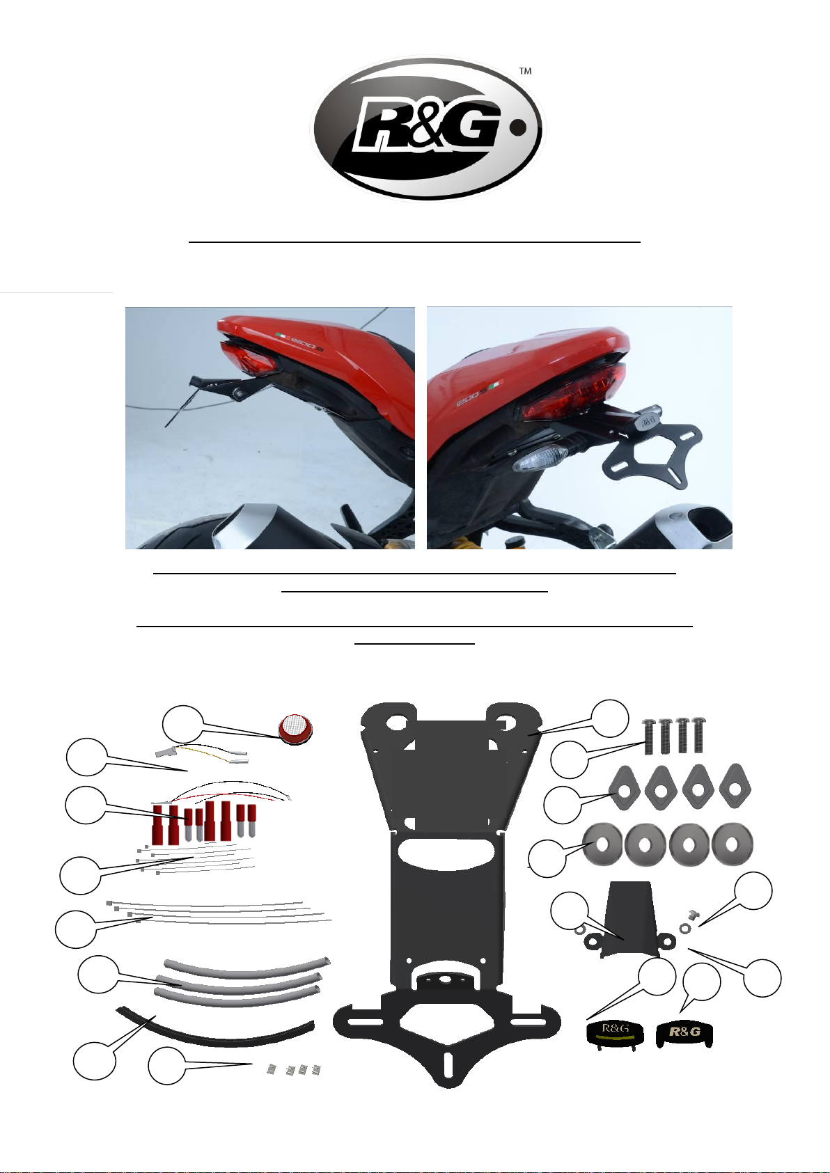
If fitting the R&G mini indicators (R&G product code RG370=bulb, RG371=LED or RG372 for Aero LED
•Fit the indicators of choice to the new licence plate bracket (item 1) (R&G mini indicator
product code RG370 for bulb type and RG371 for LED type or RG372 for Aero Style led
type) through the holes in one of the indicator adaptors (item 3) so the shaped spigot fits
into the bracket then fit another of the indicator adaptors onto the exposed end of the
indicator stem and secure and tighten the nut (please use the provided heat shrink (item
11) to protect the wiring) as shown in picture 17. Repeat for the other indicator.
•Offer this assembly into position as shown in the top pictures.
•Use the four new button head bolts (items 2) with the original washers to secure the
assembly in position.
•Route the wiring as original.
•Connect the licence plate illuminator using the supplied wiring connector (item 15) to the
original wiring plug socket.
•Connect the R&G Mini Indicators using the supplied wiring connectors (items 14) to the
original wiring plug socket. Plug it into the loom to check at this stage (if operation fails,
swap the bullet connections around). (Please use the heat-shrink (item 11) to protect the
new indicator wires). It is a good idea at this point to turn the ignition on and check for
the correct operation of all lights.
•Fit the cover (item 5) using the M4 bolts and washers (items 6 and 7).
•Use the supplied cable ties (items 12 and 13) and self-adhesive cable clips (item 9) to
secure and tidy the wiring to the bracket.
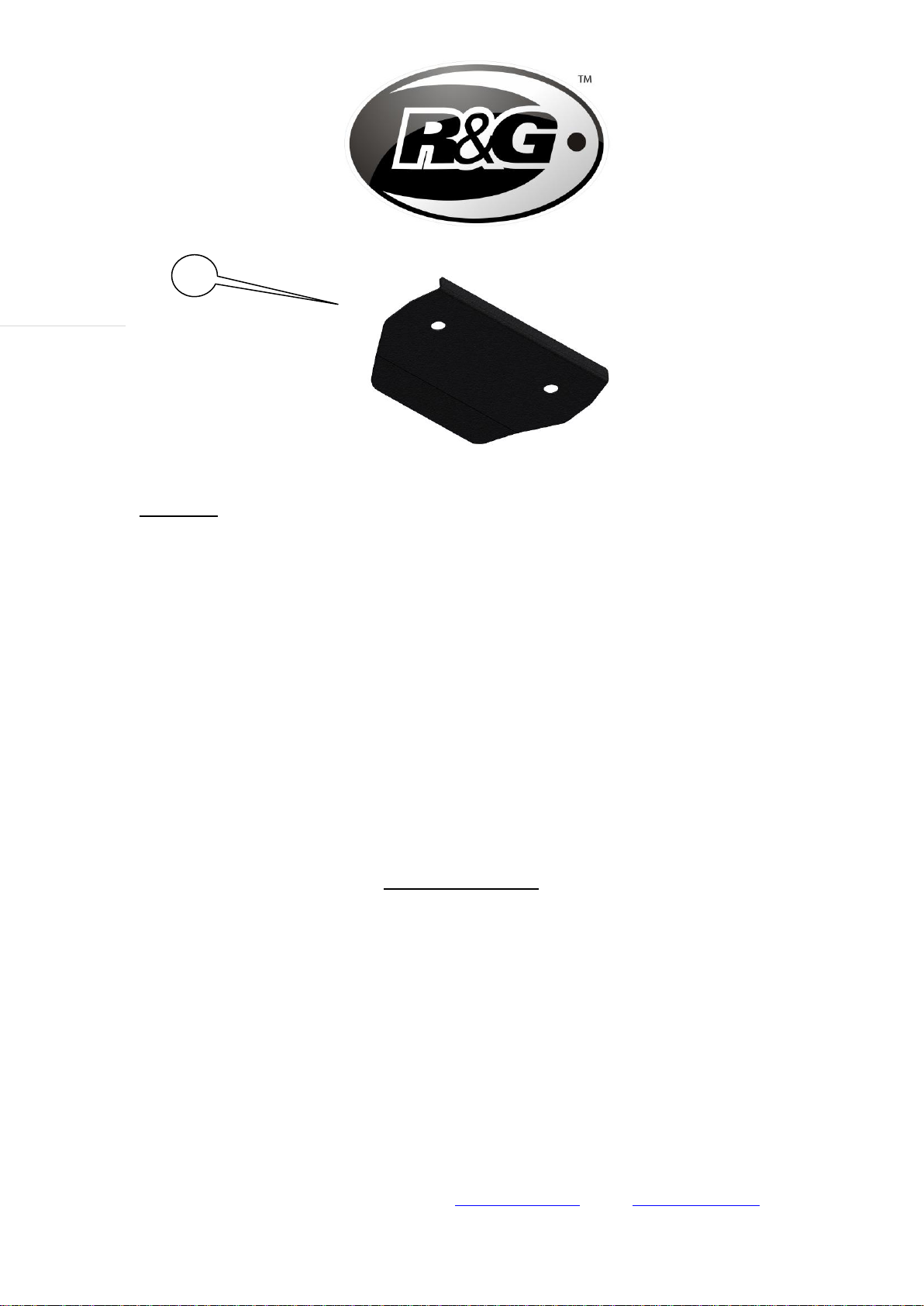
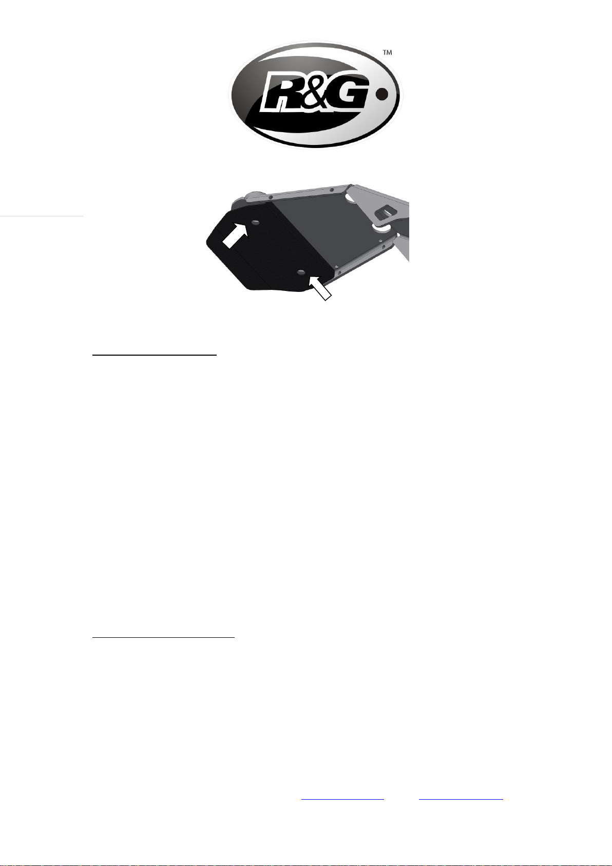
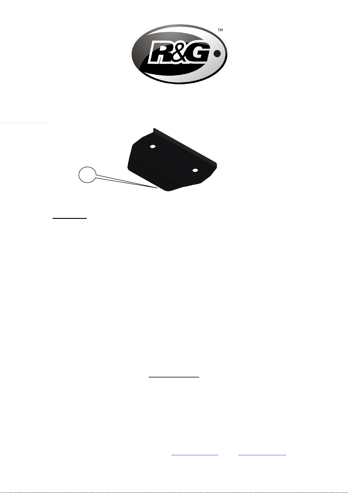
•Remove the two bolts arrowed in picture 18.
•Position the infill panel (item 17) into the plastic undertray and secure using the original
bolts as shown in picture 18
•Re-fit the licence plate (it may require drilling).
•IMPORTANT: IF FITTING A FULL-SIZE LICENCE PLATE AND PLACING IT FAR DOWN ON
THE LICENCE PLATE HANGER, THERE IS A SMALL CHANCE OF THE LICENCE PLATE
HITTING THE BACK WHEEL UNDER HEAVY LOAD AND OVER LARGE BUMPS IN THE ROAD.
IT IS YOUR RESPONSIBILITY TO CHECK FOR THIS POSSIBILITY AND TAKE AVOIDING
ACTION. FAILURE TO CHECK THIS COULD RESULT IN SERIOUS INJURY OR DAMAGE.
•Refit the seat.
•Depending on local laws, attach enclosed red reflector (item 16) in an appropriate
location.
•Please test the indicators, rear light and licence plate illuminator before riding.
Digital copies of these instructions are available to download from www.rg-racing.com
GENERAL TORQUE SETTINGS
M4 BOLT = 8Nm
M5 BOLT = 12Nm
M6 BOLT = 15Nm
M8 BOLT = 20Nm
M10 BOLT = 40Nm
ISSUE 1 13/06/2018 (DM)

LP0249
R&G
Unit 1, Shelley’s Lane, East Worldham, Alton, Hampshire, GU34 3AQ
Tel: +44 (0)1420 89007 Fax: +44 (0)1420 87301 www.rg-racing.com Email: info@rg-racing.com
8
Page | 8
CONSUMER NOTICE
The catalogue description and any exhibition of samples are only broad indications of the Products and R&G may make design
changes which do not diminish their performance or visual appeal and supplying them in such state shall conform to the order.
The Buyer acknowledges no representation or warranty (other than as to title) has been given or will apply to the Products other
than those in R&G’s order or confirmation and the Buyer confirms it has chosen the Products as being of merchantable quality
and suitable for its particular purposes. Where R&G fits the Products or undertakes other services it shall exercise reasonable
skill and care and rectify any fault free of charge unless the workmanship has been disturbed. The Buyer is responsible for
ensuring that the warranty on the motorcycle is not affected by the fitting of the Products. On return of any defective Products
R&G shall at its option either supply a replacement or refund the purchase money but shall not be liable if the Products have
been modified or used or maintained otherwise than in accordance with R&G’s or manufacturer’s instructions and good
engineering practice or if the defect arises from accident or neglect. Other than identified above and subject to R&G not limiting
its liability for causing death and personal injury, it shall not be liable for indirect or consequential loss and otherwise its liability
shall be limited to the amounts paid by the Buyer for the Products or the fitting or service concerned. These terms do not affect
the Buyer’s statutory rights.
R&G RETURNS POLICY (NON-FAULTY GOODS)
Returns must be pre-authorised (if not pre-authorised the return will be rejected). Goods may only be returned direct to us if they
were purchased direct from us (customer must prove if necessary). Otherwise to be returned to original vendor. Goods must be
in re-sellable condition, in the opinion of R&G. All returns are subject to a 25% restocking and handling fee (25% of the gross
value exc. P&P –at the prevailing price at time of purchase). The customer must pay any and all carriage charges. No returns of
discontinued products, unless within 14 days of purchase. This policy does not affect your statutory rights and does not refer to
faulty goods.

LP0249
R&G
Unit 1, Shelley’s Lane, East Worldham, Alton, Hampshire, GU34 3AQ
Tel: +44 (0)1420 89007 Fax: +44 (0)1420 87301 www.rg-racing.com Email: info@rg-racing.com
9
Page | 9
NOTICE DE MONTAGE LP0249BK SUPPORT DE PLAQUE
Ducati Monster 821 '18-, 1200 (S) '17- & 1200R '18- pour Ducati
Monster 821 (2018)
Le kit contient les articles exposés ci-dessous, vérifier que toutes les pièces soient
présentes avant de procéder au montage.
La façon dont le kit est emballé ne correspond pas forcément à la façon de monter les
pièces sur la moto.
LES PARTIES PRESENTEES PEUVENT ETRE UNIQUEMENT
REPRESENTATIVES (POUR LA CLARTE DES INSTRUCTIONS UNIQUEMENT.
2
5
1
10
6
6
11
12
7
13
8
9
16
3
4
15
14

LP0249
R&G
Unit 1, Shelley’s Lane, East Worldham, Alton, Hampshire, GU34 3AQ
Tel: +44 (0)1420 89007 Fax: +44 (0)1420 87301 www.rg-racing.com Email: info@rg-racing.com
10
Page | 10
LÉGENDE
ARTICLE 1 = PLAQUE DE FIXATION DE LA PLAQUE D’IMMATRICULATION (TB0249BK-
PARTIE 1) (x1).
ARTICLE 2 = M8x30mm BOULONS (x4).
ARTICLE 3 = ADAPTATEURS DE MINI CLIGNOTANT (I0033) (x4).
ARTICLE 4 = ENTRETOISES DE FIXATION (S1121) (x4).
ARTICLE 5 = CACHE (TB0224BK-PARTIE 2) (x1).
ARTICLE 6 = M4x5mm BOULONS (x2).
ARTICLE 7 = M4 RONDELLES (x2).
ARTICLE 8 = ASSEMBLAGE FEU DE PLAQUE (LA0002) (x1).
ARTICLE 9 = CLIPS CÂBLE AUTOCOLLANT (x4).
ARTICLE 10 = JOINT DE BORD EN CAOUTCHOUC (SRS002) (500mm DE LONG) (x1).
ARTICLE 11 = 180mm LONGUEUR DE MANCHON THERMO RÉTRACTABLE (x3).
ARTICLE 12 = COLLIER DE SERRAGES (x4).
ARTICLE 13 = PETIT COLLIER DE SERRAGES (x8).
ARTICLE 14 = CLIGNOTANTCONNECTORS (CON0004) (x2).
ARTICLE 15 = FEU DE PLAQUE CONNECTOR (CON0014) (x1).
ARTICLE 16 = REFLECTEUR (REFLECTEUR 1) (x1).
ARTICLE 17 = PANNEAU INTERNE (TB0249BK-PART 2) (x1).
Notez que si les kits sont emballés avec des rondelles en caoutchouc servant à tenir
les composants, ces rondelles doivent être jetées !
OUTILS REQUIS
•Clés Allen 3, 4 et 6mm.
•Pinces électriques.
•Un peu de superglue.
17

LP0249
R&G
Unit 1, Shelley’s Lane, East Worldham, Alton, Hampshire, GU34 3AQ
Tel: +44 (0)1420 89007 Fax: +44 (0)1420 87301 www.rg-racing.com Email: info@rg-racing.com
11
Page | 11
NOTICE DE MONTAGE
•Enlever le siège à l’aide des clés.
•Enlever les 5 boulons, voir photos 1 et 2.
•Enlever câble cache/plaque de fixation clignotant.
•Enlever les 4 boulons, voir photo 3.
•Baisser le support de plaque d’origine délicatement, voir photo 4.
•Déconnecter les 3 prises de fils du feu de plaque et les clignotants, voir photo 5 (vous
devrez couper les colliers de serrage).
•Enlever les 4 entretoises métalliques, voir photo 6.
•Enlever les 4 buissons de fixation en caoutchouc, voir photo 7.
•Monter les 4 buissons de fixation en caoutchouc sur le nouveau support de plaque (article
1), voir photo 8.
•Insérer les 4 entretoises métalliques dans les 4 buissons de fixation en caoutchouc déjà
montés sur le nouveau support de plaque (article 1), voir photo 9.
•Insérer les 4 nouvelles entretoises de fixation (article 4) sur les entretoises métalliques
d’origine, voir photo 10 (un peu d’adhésif peut être utilisé pour fixer la position des
entretoises).
•Couper le bandeau en caoutchouc en longueurs raisonnables puis collez les en position
sur le cache (article 5) et le nouveau support de plaque (article 1) voir photos 11 et 12.
•Monter le nouveau feu de plaque (article 8) sur le nouveau support de plaque (article 1)
voir photos 13 et 14 (utiliser la longueur de manchon thermo rétractable (article 11) pour
protéger les fils).
•NOTEZ QUE VOUS DEVREZ COLLER LE LINCEUL DE FEU SUR LE FEU DE
PLAQUE À LED EN UTILISANT DE LA SUPER GLUE.
Si vous réutilisez les clignotants d’origine
•Couper les colliers de serrage qui fixent le fil puis enlever le clignotant (notez de quel
côté il est parti).
•Répéter l’étape du dessus pour enlever l’autre clignotant (notez le côté).
•Tordre légèrement la tige de clignotant puis pousser dans l’ouverture du support de
plaque (article 1), voir photo 15 (un peu de graisse de silicone ou liquide détergent aide ce
process).
•Monter les clignotants sur le nouveau support de plaque (article 1) en procédant à
l’inverse de la façon dont ils ont été enlevés (veiller à ce qu’ils soient montés du bon
côté).
•Router le fil comme à l’origine.
•Reconnecter les clignotants sur les prises de fil d’origine.
•A ce stade, il est bon de vérifier que le feu de plaque et les clignotants fonctionnent
correctement (Si le feu de plaque ne s’allume pas, tournez les connecteurs).
Si vous montez les mini clignotants R&G (R&G code produit RG370=ampoule, RG371=LED ou RG372
pour LED latérale
•Montez les clignotants de votre choix sur le nouveau support de plaque (article 1) (R&G
code produit mini clignotant RG370 pour type ampoule et RG371 pour type LED ou
RG372 pour LED latérale) dans les trous d’un des adaptateurs de clignotant (article 3) de
façon à ce que le robinet se place dans le support puis monter un autre adaptateur de
clignotant sur l’extrémité de la tige de clignotant puis fixer et serrer l’écrou (utiliser la

LP0249
R&G
Unit 1, Shelley’s Lane, East Worldham, Alton, Hampshire, GU34 3AQ
Tel: +44 (0)1420 89007 Fax: +44 (0)1420 87301 www.rg-racing.com Email: info@rg-racing.com
12
Page | 12
longueur de manchon thermo rétractable (article 11) pour protéger le fil) voir photo 17.
Répéter cela pour l’autre clignotant.
•Monter l’ensemble en position comme indiqué sur les photos du dessus.
•Utiliser les 4 nouveaux boulons (articles 2) avec les rondelles d’origine pour fixer
l’ensemble en position.
•Router le fil comme à l’origine.
•Connecter le feu de plaque en utilisant le connecteur de fil fourni (article 15) sur la prise
de fil d’origine.
•Connecter les mini clignotants R&G en utilisant les connecteurs fournis (articles 14) sur
la prise de fil d’origine. Branchez la dans le faisceau pour vérifier le fonctionnement (si
l’éclairage échoue, tournez les connecteurs). (Utiliser la longueur de manchon thermo
rétractable (article 11) pour protéger les fils du nouveau clignotant). A ce stade, il est bon
de vérifier que le feu de plaque et les clignotants fonctionnent correctement.
•Monter le cache (article 5) en utilisant les boulons M4 et rondelles (articles 6 et 7).
•Utiliser les colliers de serrage fournis (articles 12 et 13) et les clips câble autocollants
(article 9) pour fixer le fil au support.
•Enlever les 2 boulons indiqués sur la photo 18.
•Positionner le panneau interne (article 17) dans le sous plateau plastique puis fixer à
l’aide des boulons d’origine, voir photo 18
•Réinstaller le siège et la plaque (peut nécessiter un perçage).
•IMPORTANT : Si vous installez une grosse plaque, il y a un risque que la
plaque entre en contact avec la roue arrière en cas de choc sur la route
(bosse, grosse charge etc..). Il est de votre responsabilité de vérifier que cela
ne puisse pas se produire. Ne pas effectuer ces vérifications peut entrainer
des dommages ainsi que des blessures graves pour le pilote.
•Remonter le siège.
•Selon les lois locales, attacher le réflecteur rouge (article 11) à l’endroit
approprié.
•Tester le feu de plaque, les clignotants, ainsi que l’ensemble des feux avant
de prendre la route.
Digital copies of these instructions are available to download from www.rg-racing.com
GENERAL TORQUE SETTINGS
M4 BOULON = 8Nm
M5 BOULON = 12Nm
M6 BOULON = 15Nm
M8 BOULON = 20Nm
M10 BOULON = 40Nm
ISSUE 1 13/06/2018 (DM)

LP0249
R&G
Unit 1, Shelley’s Lane, East Worldham, Alton, Hampshire, GU34 3AQ
Tel: +44 (0)1420 89007 Fax: +44 (0)1420 87301 www.rg-racing.com Email: info@rg-racing.com
13
Page | 13
CONSUMER NOTICE
The catalogue description and any exhibition of samples are only broad indications of the Products and R&G may make design
changes which do not diminish their performance or visual appeal and supplying them in such state shall conform to the order.
The Buyer acknowledges no representation or warranty (other than as to title) has been given or will apply to the Products other
than those in R&G’s order or confirmation and the Buyer confirms it has chosen the Products as being of merchantable quality
and suitable for its particular purposes. Where R&G fits the Products or undertakes other services it shall exercise reasonable
skill and care and rectify any fault free of charge unless the workmanship has been disturbed. The Buyer is responsible for
ensuring that the warranty on the motorcycle is not affected by the fitting of the Products. On return of any defective Products
R&G shall at its option either supply a replacement or refund the purchase money but shall not be liable if the Products have
been modified or used or maintained otherwise than in accordance with R&G’s or manufacturer’s instructions and good
engineering practice or if the defect arises from accident or neglect. Other than identified above and subject to R&G not limiting
its liability for causing death and personal injury, it shall not be liable for indirect or consequential loss and otherwise its liability
shall be limited to the amounts paid by the Buyer for the Products or the fitting or service concerned. These terms do not affect
the Buyer’s statutory rights.
R&G RETURNS POLICY (NON-FAULTY GOODS)
Returns must be pre-authorised (if not pre-authorised the return will be rejected). Goods may only be returned direct to us if they
were purchased direct from us (customer must prove if necessary). Otherwise to be returned to original vendor. Goods must be
in re-sellable condition, in the opinion of R&G. All returns are subject to a 25% restocking and handling fee (25% of the gross
value exc. P&P –at the prevailing price at time of purchase). The customer must pay any and all carriage charges. No returns of
discontinued products, unless within 14 days of purchase. This policy does not affect your statutory rights and does not refer to
faulty goods.

LP0249
R&G
Unit 1, Shelley’s Lane, East Worldham, Alton, Hampshire, GU34 3AQ
Tel: +44 (0)1420 89007 Fax: +44 (0)1420 87301 www.rg-racing.com Email: info@rg-racing.com
14
Page | 14
MONTAGEANLEITUNG FÜR LP0249BK KENNZEICHENHALTER
Kennzeichenhalter für Ducati Monster 821 '18-, 1200 (S) '17- & 1200R '18- sowie für Ducati
Monster 821 (2018)
ALLE KIT-TEILE SIND UNTEN ABGEBILDET UND GEKENNZEICHNET. BEVOR SIE MIT DER
MONTAGE BEGINNEN, ÜBERPRÜFEN SIE, DASS ALLE TEILE VORHANDEN SIND.
Hinweis: Die Verpackung der Teile stellt nicht die Reihenfolge der Montage dar.
DIE UNTEN ABGEBILDETEN TEILE DIENEN LEDIGLICH ZUR ERKLÄRUNG
2
5
1
10
6
6
11
12
7
13
8
9
16
3
4
15
14

LP0249
R&G
Unit 1, Shelley’s Lane, East Worldham, Alton, Hampshire, GU34 3AQ
Tel: +44 (0)1420 89007 Fax: +44 (0)1420 87301 www.rg-racing.com Email: info@rg-racing.com
15
Page | 15
LIEFERUMFANG
ARTIKEL 1 = KENNZEICHENHALTER (TB0249BK-TEIL 1) (x1)
ARTIKEL 2 = M8x30mm INBUSSCHRAUBEN (x4)
ARTIKEL 3 = ADAPTER FÜR DIE MINIBLINKER (I0033) (x4)
ARTIKEL 4 = DISTANZHALTER FÜR MONTAGE (S1121) (x4)
ARTIKEL 5 = ABDECKUNG (TB0249BK-TEIL 2) (x1)
ARTIKEL 6 = M4x5mm INBUSSCHRAUBEN (x2)
ARTIKEL 7 = M4 UNTERLEGSCHEIBEN (x2)
ARTIKEL 8 = KENNZEICHENBELEUCHTUNG (LA0002) (x1)
ARTIKEL 9 = SELBSTKLEBENDE KABELCLIPS (x4)
ARTIKEL 10 = KANTENSCHUTZ (SRS002) (500mm) (x1)
ARTIKEL 11 = 180mm SCHRUMPFSCHLAUCH (x3)
ARTIKEL 12 = GROSSE KABELBINDER (x4)
ARTIKEL 13 = KLEINE KABELBINDER (x8)
ARTIKEL 14 = KABELVERBINDER FÜR DIE BLINKER (CON0004) (x2)
ARTIKEL 15 = KABELVERBINDER FÜR DIE KENNZEICHENBELEUCHTUNG (CON0004) (x1)
ARTIKEL 16 = RÜCKSTRAHLER (REFL 1) (x1)
ARTIKEL 17 = VERKLEIDUNGSTEIL (x1)
Hinweis für Kits mit Plastikunterlegscheiben an den Schrauben –Diese Plastikunterlegscheiben werden nicht für
den Einbaubenötigt!
SIE BENÖTIGEN FOLGENDES WERKZEUG
•Satz Inbusschlüssel mit 3, 4 & 6 mm Inbusschlüsseln
•Elektroniker Zange
•etwas Sekundenkleber
MONTAGEANLEITUNG
•Entfernen Sie den Sitz (der Schlüssel wird hierfür benötigt).
•Entfernen Sie die fünf Schrauben, die in den Abbildungen 1 und 2 gekennzeichnet sind.
•Entfernen Sie die Kabelabdeckung/Klemmplatte aus Kunststoff für die Blinker:
•Entfernen Sie die vier Schrauben, die in Abbildung 3 gekennzeichnet sind.
•Vorsichtig den original Kennzeichenhalter herunterlassen –siehe Abbildung 4.
•Trennen Sie die drei Steckverbindungen für die Blinker und die Kennzeichenbeleuchtung
wie in Abbildung 5 abgebildet - (die Kabelbinder müssen hierbei durchgeschnitten
werden).
17

LP0249
R&G
Unit 1, Shelley’s Lane, East Worldham, Alton, Hampshire, GU34 3AQ
Tel: +44 (0)1420 89007 Fax: +44 (0)1420 87301 www.rg-racing.com Email: info@rg-racing.com
16
Page | 16
•Entfernen Sie die vier Metall-Distanzhalter, wie in Abbildung 6 abgebildet.
•Entfernen Sie die vier Gummitüllen –siehe Abbildung 7.
•Montieren Sie die vier Gummitüllen am neuen Kennzeichenhalter (Artikel 1), wie in
Abbildung 8 abgebildet.
•Montieren Sie die vier Metall-Distanzhalter in den vier bereits am neuen Kennzeichen-
halter montierten Gummitüllen –siehe Abbildung 9.
•Montieren Sie die vier neuen Distanzhalter (Artikel 4) auf den original Metall-
Distanzhaltern wie in Abbildung 10 abgebildet (etwas Klebestoff darf benutzt werden, um
diese Distanzhalter in Position zu fixieren).
•Den Kantenschutz in passende Längen schneiden und an der Abdeckung (Artikel 5) und
am neuen Kennzeichenhalter (Artikel 1) anbringen –siehe Abbildungen 11und 12.
•Montieren Sie die neue Kennzeichenbeleuchtung (Artikel 8) am neuen Kennzeichenhalter
(Artikel 1) wie in den Abbildungen 13 und 14 abgebildet (bitte den mitgelieferten
Schrumpfschlauch (Artikel 11) verwenden, um die Kabel zu schützen).
•BITTE BEACHTEN: VOR DER MONTAGE MUSS DIE LICHTABDECKUNG
MIT SEKUNDENKLEBER AN DER LED-KENNZEICHENBELEUCHTUNG
ANGEKLEBT WERDEN.
Wenn Sie die Originalblinker wiederverwenden
•Die Kabelbinder, die die Verkabelung fixieren durchschneiden und den Blinker entfernen
(bitte die entsprechende Seite notieren).
•Wiederholen Sie diesen Schritt, um den anderen Blinker ebenfalls zu entfernen (die Seite
ebenfalls notieren).
•Den Blinker vorsichtig durch die geformte Öffnung im neuen Kennzeichenhalter (Artikel
1) drücken, wie in Abbildung 15 abgebildet. (die Verwendung von etwas Silikonfett oder
Spülmittel hilft bei der Montage).
•Montieren Sie die Blinker am neuen Kennzeichenhalter (Artikel 1) wie ursprünglich (bitte
darauf achten, dass sie an der richtigen Seite angebracht werden).
•Verlegen Sie die Kabel wir ursprünglich wieder.
•Verbinden Sie die Blinker mit den original Steckverbindern.
•Es empfiehlt sich, zum jetzigen Zeitpunkt die Funktion der Beleuchtung (Blinker und
Kennzeichenhalter-Beleuchtung) zu überprüfen (falls die Kennzeichenbeleuchtung nicht
funktionieren sollte, tauschen Sie die Kabelverbinder untereinander).
Wenn Sie R&G Miniblinker montieren (R&G Artikel-Nr. RG370= mit Glühbirne, RG371=LED oder
RG372 für Aero LED
•Montieren Sie die Blinker Ihrer Wahl am neuen Kennzeichenhalter (Artikel 1) (R&G
Miniblinker Artikel-Nr. RG370 = mit Glühbirne, RG371= LED oder RG372 = Aero
LED) –einen Blinker an der Öffnung eines Miniblinker-Adapters (Artikel 3) montieren,
so dass der Zapfen in die Halterung passt, danach noch einen Adapter am
hervorstehenden Ende des Blinkers anbringen und anschließend den Blinker mit einer
Mutter befestigen (bitte verwenden Sie den mitgelieferten Schrumpfschlauch (Artikel 11),
um die Kabel zu schützen) –siehe Abbildung 17. Wiederholen Sie diesen Schritt mit dem
zweiten Blinker.
•Diese Einheit in Position bringen, wie in den oberen Abbildungen abgebildet.
•Benutzen Sie die vier neuen Inbusschrauben (Artikels 2) zusammen mit den original
Unterlegscheiben, um die Einheit in Position zu befestigen.
•Verlegen Sie die Kabel wie ursprünglich wieder.
•Den Kabelverbinder (Artikel 15) benutzen, um die Kennzeichenbeleuchtung mit dem
original Steckverbinder zu verbinden.
•Die mitgelieferten Kabelverbinder (Artikel 14) verwenden, um die R&G Miniblinker mit
dem original Steckverbinder zu verbinden. Am Kabelbaum anschließen und danach die

LP0249
R&G
Unit 1, Shelley’s Lane, East Worldham, Alton, Hampshire, GU34 3AQ
Tel: +44 (0)1420 89007 Fax: +44 (0)1420 87301 www.rg-racing.com Email: info@rg-racing.com
17
Page | 17
Funktion der Blinker und Kennzeichenbeleuchtung überprüfen (wenn sie nicht
funktionieren sollte, einfach die Kabelverbinder untereinander tauschen). Bitte den
Schrumpfschlauch (Artikel 11) benutzen, um die Kabel zu schützen. Es empfiehlt sich, zu
diesem Zeitpunkt die Zündung einzuschalten und die ordnungsgemäße Funktion der
kompletten Beleuchtung zu überprüfen.
•Montieren Sie die Abdeckung (Artikel 5) mit den M4 Schrauben und Unterlegscheiben
(Artikel 6 und 7).
•Benutzen Sie die mitgelieferten Kabelbinder (Artikel 12 und 13) und selbstklebende
Kabelclips (Artikel 9), um die Kabel am Kennzeichenhalter zu befestigen.
•Entfernen Sie die zwei Schrauben, die in Abbildung 18 gekennzeichnet sind.
•Das Verkleidungsteil (Artikel 17) in der unteren Abdeckung positionieren und mit den
Originalschrauben befestigen –siehe Abbildung 18
•Montieren Sie das amtliche Kennzeichen wieder (Bohrungen im Kennzeichen evtl.
notwendig).
•WICHTIG: WENN EIN GROSSES KENNZEICHEN ZU WEIT NACH UNTEN MONTIERT WIRD,
BESTEHT BEI SCHWERER LAST / DURCH GROSSE BODENWELLEN EIN GERINGES RISIKO,
DASS DAS KENNZEICHEN AN DAS HINTERRAD STOSSEN KANN. ES LIEGT IN IHRER
VERANTWORTUNG DIES ZU ÜBERPRÜFEN UND, WENN NOTWENDIG, VORBEUGENDE
MASSNAHMEN ZU ERGREIFEN. DIE NICHTBEACHTUNG DIESES SICHERHEITSHINWEIS
KANN ZU SCHWEREN VERLETZUNGEN FÜHREN.
•Montieren Sie den Sitz wieder.
•Entsprechend der gesetzlichen Vorschriften, den mitgelieferten Rückstrahler (Artikel 16)
anbringen.
•Überprüfen Sie die Funktion der Beleuchtung (Blinker und Kennzeichenhalter-
Beleuchtung) vor Gebrauch des Fahrzeuges.
Eine digitale Version dieser Montageanleitung kann auf folgender Seite heruntergeladen werden:
www.rg-racing.com
MAX. ANZUGSDREHMOMENTE:
M4 SCHRAUBE = 8Nm
M5 SCHRAUBE = 12Nm
M6 SCHRAUBE = 15Nm
M8 SCHRAUBE = 20Nm
M10 SCHRAUBE = 40Nm
AUSGABE 1 13/06/2018 (DM)
CONSUMER NOTICE
The catalogue description and any exhibition of samples are only broad indications of the Products and R&G may make design changes which do not diminish their
performance or visual appeal and supplying them in such state shall conform to the order. The Buyer acknowledges no representation or warranty (other than as to title) has
been given or will apply to the Products other than those in R&G’s order or confirmation and the Buyer confirms it has chosen the Products as being of merchantable
quality and suitable for its particular purposes. Where R&G fits the Products or undertakes other services it shall exercise reasonable skill and care and rectify any fault free
of charge unless the workmanship has been disturbed. The Buyer is responsible for ensuring that the warranty on the motorcycle is not affected by the fitting of the
Products. On return of any defective Products R&G shall at its option either supply a replacement or refund the purchase money but shall not be liable if the Products have
been modified or used or maintained otherwise than in accordance with R&G’s or manufacturer’s instructions and good engineering practice or if the defect arises from
accident or neglect. Other than identified above and subject to R&G not limiting its liability for causing death and personal injury, it shall not be liable for indirect or
consequential loss and otherwise its liability shall be limited to the amounts paid by the Buyer for the Products or the fitting or service concerned. These terms do not affect
the Buyer’s statutory rights. R&G RETURNS POLICY (NON-FAULTY GOODS)
Returns must be pre-authorised (if not pre-authorised the return will be rejected). Goods may only be returned direct to us if they were purchased direct from us (customer
must prove if necessary). Otherwise to be returned to original vendor. Goods must be in re-sellable condition, in the opinion of R&G. All returns are subject to a 25%
restocking and handling fee (25% of the gross value exc. P&P –at the prevailing price at time of purchase). The customer must pay any and all carriage charges. No returns
of discontinued products, unless within 14 days of purchase. This policy does not affect your statutory rights and does not refer to faulty goods.
Table of contents
Other R&G Motorcycle Accessories manuals