R&G DG0030 User manual

Page 1of 18 DG0030
R&G
Unit 1 Shelleys Lane, East Worldham, Alton, Hampshire, GU34 3AQ
Tel: +44 (0)1420 89007 www.rg-racing.com Email: info@rg-racing.com
FITTING INSTRUCTIONS FOR DG0030 DOWNPIPE GRILLE
KAWASAKI ZX6R 2019-
THIS KIT CONTAINS THE ITEMS PICTURED AND LABELLED BELOW.
DO NOT PROCEED UNTIL YOU ARE SURE ALL PARTS ARE PRESENT.
Please note that the way the kit is packed does not necessarily represent the way of mounting to
the bike
Please note that in cases where kits are packed with rubber washers holding the components onto the bolt –
the rubber washers should be thrown away!
THE PARTS SHOWN MAY BE REPRESENTATIVE ONLY (FOR CLARITY OF INSTRUCTIONS ONLY)
Digital copies of these instructions are available to download from
www.rg-racing.com
GENERAL TORQUE SETTINGS
M4 BOLT = 8Nm
M5 BOLT = 12Nm
M6 BOLT = 15Nm
M8 BOLT = 20Nm
M10 BOLT = 40Nm
TOOLS REQUIRED
•Socket set to include 10mm socket, wrench & extension.
•3mm & 4mm Allen key
•Cross headed screwdriver.
•Small flat bladed screwdriver

Page 7of 18 DG0030
R&G
Unit 1 Shelleys Lane, East Worldham, Alton, Hampshire, GU34 3AQ
Tel: +44 (0)1420 89007 www.rg-racing.com Email: info@rg-racing.com
FITTING INSTRUCTIONS
•To fit the Downpipe Grille, the RHS side fairing (as you sit on the bike) must be
removed. To do this, start by removing the upper RHS side panel that is shown in
picture 1.
•This panel comes away in 2 parts, the rear section of this panel is held in by a
push rivet which can be removed by pressing in the centre of the rivet to release
the expander.
•Remove the rivet and rear 4mm allen screw visible on the panel arrowed in
picture 1.
•The panels are held in place by rubber grommets on the rear of the panels, pull
gently to remove the rear plastic panel.
•You should now remove the upper allen screw as shown in picture 2.
•Now carefully remove the second upper panel, noting 2 more grommets on the
inside of the panel, one of which is mounted horizontally, so the plastic must
move across the bike towards the speedo as arrowed in picture 3 to remove.
•The upper, mid and lower sections of the RHS fairing will be removed as one
piece, to remove, first locate a 10mm bolt behind the smaller panels removed in
the previous steps, remove this with a ratchet with extension as shown in picture
4.
•Remove the 4mm allen bolt also hidden behind the main RHS fairing piece as
arrowed in picture 5.
•Next, disconnect the RHS fairing from the left by removing 2 x push rivets in the
lower section of the fairing as shown in pictures 6 and 7.
•3 push rivets connect the radiator cowl to the RHS fairing, remove these as
shown in picture 8.
•Remove the two fairing bolts as arrowed in pictures 9 & 10.
•Ensure that all fixtures are removed before attempting to pull the fairing from the
bike. Follow the next steps carefully, do not use excessive force.
•Before proceeding, be aware the full removal of the fairing may require a
second person to hold the fairing assembly while the charcoal canister
and indicator wire are disconnected as these are affixed to the inside of
the faring.
•Starting from the rear of the fairing, gently pull the fairing under the seat away
from the bike, this will release a rubber grommet.
•Starting from the rear of the fairing gently flex the panel away from the bike
moving towards the front of the bike, the section below the tank is held to the
bike via Velcro pad and rubber grommet.
•The fairing piece should be loose, but several hidden tabs will prevent full
removal.
•The upper section of the fairing in connected to the nose of the bike via a plastic
tab beneath the headlight (shown in picture 11), and 2 locating pins shown in
picture 12.
•While supporting the entire fairing, slide the assembly towards the front of the
bike to disengage 2 rubber locating pins as shown in picture 13.
•Hold the fairing and have an assistant disconnect the charcoal canister from the
fairing using a cross head screwdriver to remove 3 screws as shown in picture 14.
•Next disconnect the blue and grey electrical connectors using a small flat bladed
screwdriver to lift the locking tab as shown in pictures 15 and 16.
•Now you can remove the fairing away from the bike and store safely while you
proceed.
•You will now have access to the lower radiator mount, remove the 10mm hex bolt
as shown in picture 17.

Page 8of 18 DG0030
R&G
Unit 1 Shelleys Lane, East Worldham, Alton, Hampshire, GU34 3AQ
Tel: +44 (0)1420 89007 www.rg-racing.com Email: info@rg-racing.com
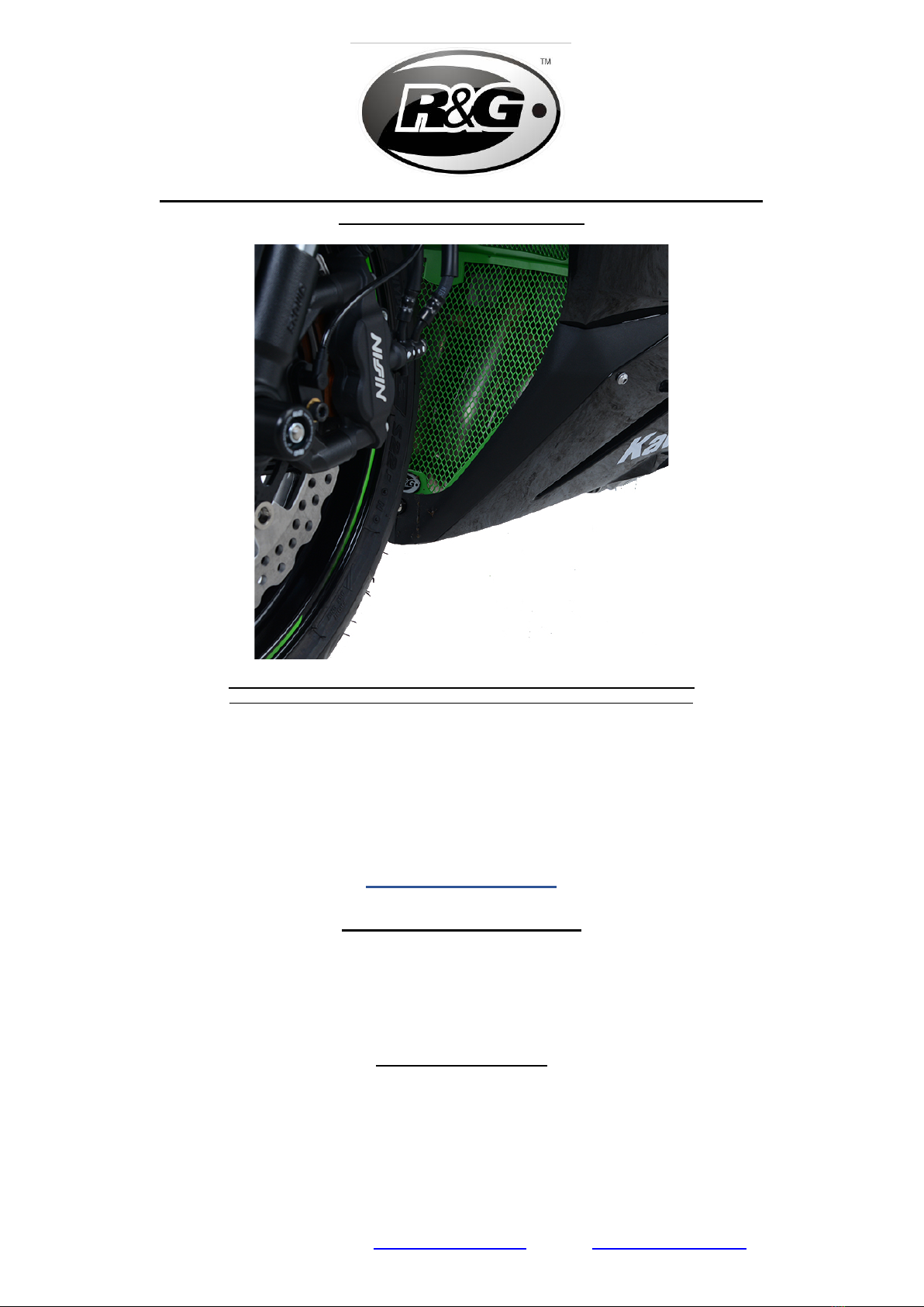
•You can now take the radiator guard and slide this into place ensuring that the
bend in the side profile of the downpipe grille sits snugly into the LHS fairing as
shown in picture 18. Any plastic tabs located inside of the fairing should sit
behind the grille component to hold this firmly in place.
•Line up the upper downpipe grille mount with the lower radiator mount and
replace the OEM 10mm hex bolt and tighten to the correct torque as shown in
picture 19, (some Loctite or similar may be used to ensure this bolt remains in
place, as access is limited with DG fitted).
•If fitting with an R&G Radiator Guard in place, ensure the radiator guard lower
mount sits between the downpipe grille mount and radiator mount.
•Ensure that the lower mount lines up with the lower fairing join as in picture 20.
•You can now reassemble the fairing in the reverse order as it was removed,
making sure to correctly line up the downpipe grille with the RHS of the fairing as
it is placed back onto the bike. Ensure to reconnect all electrical connections.
•When the main fairing panel is affixed to the bike, ensure the lower connection
mount holes line up together.
•At this stage, on the bellypan section of the fairing, locate both sides together
and fit Spacer 1115 (Item 2) into the lower mount with the small boss locating
into the fairing and affix the M5 bolt (item 3) through the spacer, both fairing
mounts and the lower grille mount.
•This should be fastened with the M5 washer (item 5) and Nyloc nut (item 4) by
using your 10mm socket and extension to access the nut from underneath the
fairing, whilst stopping the bolt (item 3) from turning with your 3mm Allen key as
demonstrated in pictures 21 and 22.
•Now you can complete the re-fitting of the upper dashboard fairing panels.
•Ensure the Downpipe Grille is installed correctly and fitted securely.
•Ensure all panels and bolts are secure and torqued correctly before riding.
ISSUE 1 07/03/2019 (DM)
CONSUMER NOTICE
The catalogue description and any exhibition of samples are only broad indications of the Products and R&G
may make design changes which do not diminish their performance or visual appeal and supplying them in
such state shall conform to the order. The Buyer acknowledges no representation or warranty (other than as to
title) has been given or will apply to the Products other than those in R&G’s order or confirmation and the
Buyer confirms it has chosen the Products as being of merchantable quality and suitable for its particular
purposes. Where R&G fits the Products or undertakes other services it shall exercise reasonable skill and care
and rectify any fault free of charge unless the workmanship has been disturbed. The Buyer is responsible for
ensuring that the warranty on the motorcycle is not affected by the fitting of the Products. On return of any
defective Products R&G shall at its option either supply a replacement or refund the purchase money but shall
not be liable if the Products have been modified or used or maintained otherwise than in accordance with
R&G’s or manufacturer’s instructions and good engineering practice or if the defect arises from accident or
neglect. Other than identified above and subject to R&G not limiting its liability for causing death and personal
injury, it shall not be liable for indirect or consequential loss and otherwise its liability shall be limited to the
amounts paid by the Buyer for the Products or the fitting or service concerned. These terms do not affect the
Buyer’s statutory rights.
R&G RACING RETURNS POLICY (NON-FAULTY GOODS)
Returns must be pre-authorised (if not pre-authorised the return will be rejected). Goods may only be returned
direct to us if they were purchased direct from us (customer must prove if necessary). Otherwise to be
returned to original vendor. Goods must be in re-sellable condition, in the opinion of R&G Racing. All returns
are subject to a 25% restocking and handling fee (25% of the gross value exc. P&P – at the prevailing price at
time of purchase). The customer must pay any and all carriage charges. No returns of discontinued products,
unless within 14 days of purchase. This policy does not affect your statutory rights and does not refer to faulty
goods.

Page 9of 18 DG0030
R&G
Unit 1 Shelleys Lane, East Worldham, Alton, Hampshire, GU34 3AQ
Tel: +44 (0)1420 89007 www.rg-racing.com Email: info@rg-racing.com
NOTICE DE MONTAGE POUR DG0030 PROTECTION DES
COLLECTEURS D’ÉCHAPPEMENT
KAWASAKI ZX6R 2019-
LE KIT CONTIENT LES ARTICLES EXPOSES CI-DESSOUS,VERIFIER QUE TOUTES LES
PIECES SOIENT PRESENTES AVANT DE PROCEDER AU MONTAGE.
La façon dont le kit est emballé ne correspond pas forcément à la façon de monter les pièces sur la
moto.
Notez que si les kits sont emballés avec des rondelles en caoutchouc servant à tenir les composants, ces
rondelles doivent être jetées !
LES PARTIES PRESENTÉES PEUVENT ETRE UNIQUEMENT REPRESENTATIVES (POUR LA
CLARTE DES INSTRUCTIONS UNIQUEMENT)
Notice disponible au téléchargement sur www.rg-racing.com
VALEURS DE SERRAGE RECOMMANDEES
M4 BOULON =8NM
M5 BOULON =12NM
M6 BOULON =15NM
M8 BOULON =20NM
M10 BOULON =40NM
OUTILS REQUIS
•Clé à cliquet et douilles 10mm.
•Clé Allen 3mm & 4mm
•Tournevis cruciforme.
•Tournevis plat

Page 11 of 18 DG0030
R&G
Unit 1 Shelleys Lane, East Worldham, Alton, Hampshire, GU34 3AQ
Tel: +44 (0)1420 89007 www.rg-racing.com Email: info@rg-racing.com
NOTICE DE MONTAGE
•Pour monter la grille, le carénage du côté droit (lorsqu’on est assis sur la moto)
doit être enlevé. Pour cela, commencer par enlever le carénage supérieur droit,
voir photo 1.
•Le panneau s’enlève en 2 parties, la partie arrière du panneau est maintenue par
un rivet qui peut être enlevé en pressant au milieu pour libérer l’expandeur.
•Enlever le rivet et la vis 4mm visible sur le panneau, voir photo 1.
•Les panneaux sont tenus en place par des œillets en caoutchouc à l’arrière des
panneaux tirer doucement pour enlever le panneau plastic arrière.
•Vous pouvez à présent enlever la vis supérieure, voir photo 2.
•Enlever doucement le 2nd panneau supérieur, en notant qu’il y 2 rivets
supplémentaires à l’intérieur du panneau, un d’eux est monté à l’horizontal, de
façon à ce que plastique puisse bouger à travers la moto vers le speedo, voir
photo 3 pour l’enlever.
•La section supérieure, intermédiaire, et inférieure du carénage droit seront
enlevés en 1 pièce, pour l’enlever, commencez par placer un boulon 10mm
derrière des plus petits panneaux enlevés dans les étapes supérieures, enlevez le
carénage à l’aide d’une clé à cliquet, munie d’une extension, voir photo 4.
•Enlever le boulon 4mm cache derrière le carénage droit principal, voir photo 5.
•Ensuite, déconnecter le carénage droit du côté gauche en enlevant les 2 rivets de
la section inférieure du carénage, voir photos 6 et 7.
•3 rivets connectent le capot de radiateur au carénage du côté droit, enlever les
comme sur la photo 8.
•Enlever les 2 boulon de carénage, voir photos 9 & 10.
•Veiller à ce que toutes les fixations soient enlevées avant de tirer le carénage de
la moto. Suivre les étapes suivantes attentivement, ne pas trop forcer.
Avant de procéder, gardez à l’esprit que le démontage du carénage
nécessite d’être accompagné d’une 2e personne pour tenir le carénage
tandis que le morceau de charbon de bois et le fil de clignotant sont
déconnectés, car ils sont connectés à l’intérieur de la moto.
•En commençant par l’arrière du carénage, tirer le carénage sous le siège en
dehors de la moto, cela libèrera un œillet en caoutchouc.
•En commençant par l’arrière du carénage, écartez doucement le panneau de la
moto vers l’avant de la moto, la section sous le réservoir est attachée à la moto
via un Velcro et un œillet en caoutchouc.
•La pièce de carénage doit être desserrée, mais quelques onglets cachés éviteront
qu’il se retire complètement.
•La section supérieure du carénage est connectée au nez de la moto par un onglet
plastique sous le feu (voir photo 11), puis 2 broches de positionnement, voir
photo 12.
•Tout en supportant l’ensemble du carénage, glisser l’ensemble vers l’avant de la
moto pour libérer 2 onglets en caoutchouc, voir photo 13.
•Tenir le carénage et demandez l’aide d’un assistant pour déconnecter le morceau
de charbon du carénage en utilisant un tournevis pour enlever les 3 vis, voir
photo 14.
•Déconnectez ensuite les connecteurs électriques bleu et gris en utilisant un petit
tournevis plat pour soulever l’onglet de blocage, voir photos 15 et 16.
•A présent vous pouvez enlever le carénage de la moto, et le ranger
soigneusement en attendant.
•Vous aurez à présent accès au support radiateur inférieure, enlever le boulon
10mm, voir photo 17.

Page 12 of 18 DG0030
R&G
Unit 1 Shelleys Lane, East Worldham, Alton, Hampshire, GU34 3AQ
Tel: +44 (0)1420 89007 www.rg-racing.com Email: info@rg-racing.com
•Vous pouvez à présent prendre la protection radiateur et la glisser en place en
veillant à ce que le coude du profil latéral de protection des collecteurs se place
dans le carénage gauche, voir photo 18. Tout onglet en plastique situé à
l’intérieur du carénage doit se placer derrière la grille pour la maintenir
fermement en place.
•Aligner le support de grille de protection supérieur avec le support de grille de
protection inférieur puis replacez le boulon d’origine 10mm puis serrer aux
valeurs de serrages recommandées, voir photo 19, (un peu de Loctite, ou produit
similaire, peut être utilisée pour fixer le boulon en place, car l’accès sera limité
une fois la grille montée).
•Si le montage s’effectue alors qu’une protection radiateur R&G est en place,
veiller à ce que le support inférieur de la protection radiateur se place entre le
support de la grille de protection et le support radiateur.
•Veiller à ce que le support inférieur s'aligne avec la jointure inférieure du
carénage, voir photo 20.
•Vous pouvez à présent réassembler le carénage dans le sens inverse de son
démontage, en veillant à aligner correctement la grille de protection avec le
carénage droit, placé sur la moto. Veiller à reconnecter toutes les connexions
électriques.
•Lorsque le panneau de carénage principal est fixé sur la moto, veiller à ce que les
trous du support de connexion inférieur s’alignent ensemble.
•A ce stade, sur la partie ventre plat du carénage, placer les 2 côtés ensemble puis
insérer une entretoise 1115 (Article 2) dans le support inférieur avec le petit
patron placé dans le carénage, puis insérer un boulon M5 (article 3) dans
l’entretoise, les 2 supports de carénage et le support de grille inférieur.
•La grille doit être attaché avec une rondelle M5 (article 5) et un écrou (article 4) à
l’aide d’une clé à cliquet + douille 10mm et d’une extension, pour accéder à
l’écrou par le dessous du carénage, tout en empêchant le boulon (article 3) de
tourner, à l’aide d’une clé Allen 3mm, voir photos 21 et 22.
•A présent, vous pouvez compléter le réassemblage des panneaux de carénage
supérieurs du tableau de bord.
•Veiller à ce que la grille de protection des collecteurs soit installée correctement.
•Veiller à ce que tous les panneaux et boulons soient fixés correctement avant de
prendre la route.
ISSUE 1 07/03/2019 (DM)
CONSUMER NOTICE
The catalogue description and any exhibition of samples are only broad indications of the Products and R&G
may make design changes which do not diminish their performance or visual appeal and supplying them in
such state shall conform to the order. The Buyer acknowledges no representation or warranty (other than as to
title) has been given or will apply to the Products other than those in R&G’s order or confirmation and the
Buyer confirms it has chosen the Products as being of merchantable quality and suitable for its particular
purposes. Where R&G fits the Products or undertakes other services it shall exercise reasonable skill and care
and rectify any fault free of charge unless the workmanship has been disturbed. The Buyer is responsible for
ensuring that the warranty on the motorcycle is not affected by the fitting of the Products. On return of any
defective Products R&G shall at its option either supply a replacement or refund the purchase money but shall
not be liable if the Products have been modified or used or maintained otherwise than in accordance with
R&G’s or manufacturer’s instructions and good engineering practice or if the defect arises from accident or
neglect. Other than identified above and subject to R&G not limiting its liability for causing death and personal
injury, it shall not be liable for indirect or consequential loss and otherwise its liability shall be limited to the
amounts paid by the Buyer for the Products or the fitting or service concerned. These terms do not affect the
Buyer’s statutory rights.

Page 13 of 18 DG0030
R&G
Unit 1 Shelleys Lane, East Worldham, Alton, Hampshire, GU34 3AQ
Tel: +44 (0)1420 89007 www.rg-racing.com Email: info@rg-racing.com
R&G RACING RETURNS POLICY (NON-FAULTY GOODS)
Returns must be pre-authorised (if not pre-authorised the return will be rejected). Goods may only be returned
direct to us if they were purchased direct from us (customer must prove if necessary). Otherwise to be
returned to original vendor. Goods must be in re-sellable condition, in the opinion of R&G Racing. All returns
are subject to a 25% restocking and handling fee (25% of the gross value exc. P&P – at the prevailing price at
time of purchase). The customer must pay any and all carriage charges. No returns of discontinued products,
unless within 14 days of purchase. This policy does not affect your statutory rights and does not refer to faulty
goods.

Page 14 of 18 DG0030
R&G
Unit 1 Shelleys Lane, East Worldham, Alton, Hampshire, GU34 3AQ
Tel: +44 (0)1420 89007 www.rg-racing.com Email: info@rg-racing.com
MONTAGEANLEITUNG FÜR DG0030 KRÜMMERSCHUTZGITTER
KAWASAKI ZX6R 2019-
ALLE KIT-TEILE SIND UNTEN ABGEBILDET UND GEKENNZEICHNET. ÜBERPRÜFEN SIE, DASS ALLE
TEILE VORHANDEN SIND, BEVOR SIE MIT DER MONTAGE BEGINNEN.
Hinweis: Die Verpackung der Teile stellt nicht die Reihenfolge der Montage dar.
Hinweis für Kits mit Plastikunterlegscheiben an den Schrauben – Diese Plastikunterlegscheiben werden nicht für
den Einbau benötigt!
DIE UNTEN ABGEBILDETEN TEILE DIENEN LEDIGLICH ZUR ERKLÄRUNG
Eine digitale Version dieser Montageanleitung kann auf folgender Seite
heruntergeladen werden www.rg-racing.com
MAX. ANZUGSDREHMOMENT
M4 SCHRAUBE = 8Nm
M5 SCHRAUBE = 12Nm
M6 SCHRAUBE = 15Nm
M8 SCHRAUBE = 20Nm
M10 SCHRAUBE = 40Nm
SIE BENÖTIGEN FOLGENDES
•Satz Steckschlüssel mit 10mm Steckschlüssel und Verlängerung
•3mm & 4mm Inbusschlüssel
•Kreuzschlitzschraubendreher
•Schraubendreher

Page 15 of 18 DG0030
R&G
Unit 1 Shelleys Lane, East Worldham, Alton, Hampshire, GU34 3AQ
Tel: +44 (0)1420 89007 www.rg-racing.com Email: info@rg-racing.com
LIEFERUMFANG
ARTIKEL 1 = KRÜMMERSCHUTZGITTER (DG0030)
ARTIKEL 2 = S1115 DISTANZHALTER
ARTIKEL 3 = M5 SCHRAUBE
ARTIKEL 4 = M5 SELBSTSICHERNDE MUTTER
ARTIKEL 5 = UNTERLEGSCHEIBE

Page 16 of 18 DG0030
R&G
Unit 1 Shelleys Lane, East Worldham, Alton, Hampshire, GU34 3AQ
Tel: +44 (0)1420 89007 www.rg-racing.com Email: info@rg-racing.com
MONTAGEANLEITUNG
•Um das Krümmerschutzgitter montieren zu können, muss die Seitenverkleidung
an der rechten Seite (in Fahrtrichtung) entfernt werden. Fangen Sie an, indem
Sie das obere Seitenverkleidungsteil entfernen – siehe Abbildung 1.
•Dieses Verkleidungsteil wird in 2 Teilen entfernt – das hintere Teil ist mit einer
Plastikniete befestigt – einfach mittig eindrücken, um den Expander zu lösen.
•Entfernen Sie die Plastikniete und die hintere 4mm Inbusschraube, die an der
Verkleidung mit einem Pfeil gekennzeichnet ist – siehe Abbildung 1.
•Die Verkleidungsteile sind hinten mit einer Gummitülle in Position befestigt –
vorsichtig ziehen, um das hintere Verkleidungsteil zu entfernen.
•Entfernen Sie nun die obere Inbusschraube wie in Abbildung 2 abgebildet.
•Danach entfernen Sie das zweite obere Verkleidungsteil – es sind zwei weitere
Gummitüllen an der Innenseite des Verkleidungsteils. Eine Gummitülle ist
horizontal montiert, sodass das Plastik quer über das Motorrad in Richtung Tacho
bewegt werden muss, wie in Abbildung 3 gekennzeichnet, um dies zu entfernen.
•Der obere, mittlere und untere Teil der rechten Verkleidung wird als ein
Gesamtteil entfernt. Lokalisieren Sie die 10mm Schraube hinter den zuvor
entfernten kleineren Verkleidungsteilen und entfernen Sie sie – siehe Abbildung
4.
•Entfernen Sie die 4mm Inbusschraube, die ebenfalls hinteren dem
Hauptverkleidungsteil versteckt ist – siehe Abbildung 5.
•Als nächstes, die rechte Seitenverkleidung von links entfernen, indem Sie die zwei
Plastiknieten im unteren Teil der Verkleidung entfernen–siehe Abbildungen 6 & 7.
•3 Plastiknieten verbinden die Verkleidung für den Kühler an der rechten
Seitenverkleidung – entfernen Sie diese wie in Abbildung 8 abgebildet.
•Entfernen Sie die zwei Verkleidungsschrauben, die in den Abbildungen 9 & 10
markiert sind.
•Stellen Sie sicher, dass alle Fixierungen entfernt sind, bevor Sie versuchen, die
Verkleidung vom Motorrad wegzuziehen. Die nächsten Schritte mit Vorsicht
ausführen, bitte nicht zu viel Kraft anwenden!
•Achtung – eine zweite Person wird eventuell bei die Entfernung der
Seitenverkleidung gebraucht, um die Verkleidung zu halten während der
Aktivkohlefilter und die Kabel für die Blinker getrennt werden (diese sind
an der Innenseite der Verkleidung fixiert).
•Fangen Sie am hinteren Teil der Verkleidung an. Vorsichtig die Verkleidung von
unter dem Sitz wegziehen, sodass eine Gummitülle gelöst wird.
•Fangen Sie am hinteren Teil der Verkleidung an und biegen Sie das
Verkleidungsteil weg vom Motorrad – in Richung Vorderteil das Motorrades
bewegen – das Verkleidungsteil unter dem Tank ist mit Klettband und einer
Gummitülle am Motorrad befestigt.
•Das Verkleidungsteil sollte locker sein, aber die versteckten Laschen verhindern
die komplette Entfernung.
•Das obere Teil der Verkleidung ist durch eine Kunststofflasche unter dem
Scheinwerfer (siehe Abbildung 11) und 2 Fixierstifte (siehe Abbildung 12) mit
dem Vorderteil des Motorrads verbunden.
•Während Sie die komplette Verkleidung stützen, schieben Sie die Einheit nach
vorne, um die zwei Fixierstifte aus Kunststoff zu lösen – siehe Abbildung 13.
•Halten Sie die Verkleidung fest und lassen Sie einen Helfer den Aktivkohlefilter
von der Verkleidung entfernen – die drei Schrauben, die hierbei entfernt werden
sind in Abbildung 14 abgebildet.

Page 17 of 18 DG0030
R&G
Unit 1 Shelleys Lane, East Worldham, Alton, Hampshire, GU34 3AQ
Tel: +44 (0)1420 89007 www.rg-racing.com Email: info@rg-racing.com
•Trennen Sie den blauen und den grauen elektrischen Steckverbinder – benutzen
Sie einen kleinen Schraubenzieher, um die Laschen zu heben –siehe Abbildungen
15 & 16.
•Die Verkleidung nun vom Motorrad entfernen und zur Seite stellen.
•Sie werden jetzt Zugang zu der unteren Kühlerhalterung haben – entfernen Sie
die 10mm Sechskantschraube, die in Abbildung 17 abgebildet ist.
•Jetzt können Sie den Kühlerschutz nehmen und in Position schieben – bitte darauf
achten, dass die Biegung im Profil an der Seite des Krümmerschutzgitters gut in
die Verkleidung für die linke Seite passt – siehe Abbildung 18. Die Plastiklaschen
an der Innenseite der Verkleidung sollen hinter dem Krümmerschutzgitter
positioniert sein, um diese fest in Position zu halten.
•Die obere Halterung mit der unteren Halterung für den Kühler ausrichten und die
original 10mm Sechskantschraube wieder anbringen und mit dem richtigen
Drehmoment befestigen - siehe Abbildung 19 (etwas Schraubensicherung z.B.
Loctite darf verwendet werden, um sicherzustellen, dass diese Schraube in
Position bleibt, da der Zugang begrenzt ist sobald das Krümmerschutzgitter
montiert ist).
•Bei der gleichzeitigen Montage eines R&G Kühlerschutzes, bitte darauf achten,
dass die untere Halterung für den Kühlerschutz zwischen der Halterung für das
Krümmerschutzgitter und der Halterung für den Kühlerschutz positioniert ist.
•Stellen Sie sicher, dass die untere Halterung mit der unteren Verbindung des
Verkleidungsteils ausgerichtet ist – siehe Abbildung 20.
•Die Verkleidung können Sie nun einfach wieder montieren, indem Sie die Schritte,
die oben für die Entfernung beschrieben wurden, in umgekehrter Reihenfolge
ausführen. Achten Sie darauf, dass das Krümmerschutzgitter mit der rechten
Seite der Verkleidung richtig ausgerichtet ist, wenn sie wieder am Motorrad
montiert ist. Bitte stellen Sie sicher, dass alle elektrischen Verbindungen wieder
angeschlossen sind.
•Wenn das Hauptverkleidungsteil am Motorrad fixiert ist, bitte überprüfen Sie,
dass die unteren Montageöffnungen miteinander ausgerichtet sind.
•Nun beide Seiten unten an der unteren Verkleidung zusammenführen und den
Distanzhalter 1115 (Artikel 2) in der unteren Halterung anbringen – der kleine
Gewindeeinsatz passt in die Verkleidung und die M5 Schraube (Artikel 3) durch
den Distanzhalter, beide Halterungen für die Verkleidung und die untere
Halterung für das Krümmerschutz montieren.
•Dies soll mit der M5 Unterlegscheibe (Artikel 5) und der selbstsichernden Mutter
(Artikel 4) befestigt werden – benutzen Sie hierfür einen 10mm Steckschlüssel
mit Verlängerung, um Zugang zu der Mutter von der Unterseite der Verkleidung
zu ermöglichen während Sie die Schraube (Artikel 3) mit einem 3mm
Inbusschlüssel festhalten, so dass sie sich nicht dreht – siehe Abbildungen 21 &
22.
•Nun können Sie die Wiedermontage der oberen Verkleidungsteile am
Instrumentenbrett zu Ende führen.
•Stellen Sie sicher, dass das Krümmerschutzgitter ordnungsgemäß montiert und
sicher befestigt ist.
•Überprüfen Sie, dass alle Verkleidungsteile und Schrauben sicher befestigt und
mit dem richtigen Anzugsdrehmoment angezogen sind, bevor Sie mit dem
Motorrad fahren.
AUSGABE 1 07/03/2019 (DM)

Page 18 of 18 DG0030
R&G
Unit 1 Shelleys Lane, East Worldham, Alton, Hampshire, GU34 3AQ
Tel: +44 (0)1420 89007 www.rg-racing.com Email: info@rg-racing.com
CONSUMER NOTICE
The catalogue description and any exhibition of samples are only broad indications of the Products and R&G may make design changes which do not
diminish their performance or visual appeal and supplying them in such state shall conform to the order. The Buyer acknowledges no representation
or warranty (other than as to title) has been given or will apply to the Products other than those in R&G’s order or confirmation and the Buyer
confirms it has chosen the Products as being of merchantable quality and suitable for its particular purposes. Where R&G fits the Products or
undertakes other services it shall exercise reasonable skill and care and rectify any fault free of charge unless the workmanship has been disturbed.
The Buyer is responsible for ensuring that the warranty on the motorcycle is not affected by the fitting of the Products. On return of any defective
Products R&G shall at its option either supply a replacement or refund the purchase money but shall not be liable if the Products have been modified
or used or maintained otherwise than in accordance with R&G’s or manufacturer’s instructions and good engineering practice or if the defect arises
from accident or neglect. Other than identified above and subject to R&G not limiting its liability for causing death and personal injury, it shall not be
liable for indirect or consequential loss and otherwise its liability shall be limited to the amounts paid by the Buyer for the Products or the fitting or
service concerned. These terms do not affect the Buyer’s statutory rights.
R&G RACING RETURNS POLICY (NON-FAULTY GOODS)
Returns must be pre-authorised (if not pre-authorised the return will be rejected). Goods may only be returned direct to us if they were purchased
direct from us (customer must prove if necessary). Otherwise to be returned to original vendor. Goods must be in re-sellable condition, in the
opinion of R&G Racing. All returns are subject to a 25% restocking and handling fee (25% of the gross value exc. P&P – at the prevailing price at
time of purchase). The customer must pay any and all carriage charges. No returns of discontinued products, unless within 14 days of purchase.
This policy does not affect your statutory rights and does not refer to faulty goods.
Table of contents
Languages:
Other R&G Motorcycle Accessories manuals
Popular Motorcycle Accessories manuals by other brands

Rockford Fosgate
Rockford Fosgate DSR1 instructions

hepco & becker
hepco & becker 6547566 01 01 quick start guide

hepco & becker
hepco & becker Easyrack manual

hepco & becker
hepco & becker LEGACY 636669 00 01L quick start guide

hepco & becker
hepco & becker 6306502 00 01 quick start guide

Buhel
Buhel D01 instruction manual

hepco & becker
hepco & becker 8009521 00 01 manual

Leatt
Leatt NECK BRACE user manual

HealTech Electronics
HealTech Electronics iLogger easy Supplementary manual

hepco & becker
hepco & becker Easyrack 661715 01 01 installation instructions

SIP
SIP 03634 user manual

Dynojet
Dynojet Power Commander V Ex installation instructions