manuals.online logo
Brands
  1. Home
  2. •
  3. Brands
  4. •
  5. Ravaglioli
  6. •
  7. Lifting System
  8. •
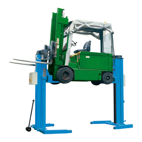
  9. Ravaglioli RAV241 User manual

Ravaglioli RAV241 User manual

0523-M008-0 Rev. n. 1 (02-2008)
0523-M008-0
Redatto da ESSEBI (Bologna)
- Per eventuali chiarimenti interpellare il più vicino rivenditore oppure rivolgersi direttamente a
Servizio assistenza tecnica: R V GLIOLI S.p. - 40037 Pontecchio Marconi - Bologna Italia - Via 1° Maggio, 3
Tel. (051) 6781511 - Telex 510697 R V I - Fax (051) 846349
- For any further information please contact your local dealer or call:
R V GLIOLI S.p. . - fter Sales Service - Via 1° Maggio, 3 - 40037 Pontecchio Marconi - Bologna - Italy
Phone +39 (051) 6781511 - Telex 510697 R V I - Fax +39 (051) 846349
- Im Zweifelsfall ober bei Rückfragen wenden Sie sich bitte an den nächsten Wiederverkäufer oder direkt an:
R V GLIOLI S.p. . - Kundendienst - Via 1° Maggio, 3 - 40037 Pontecchio Marconi - Bologna - Italien
Telefon +39 (051) 6781511 - Telex 510697 R V I - Fax +39 (051) 846349
- Pour tout renseignement complémentaire sadresser au revendeur le plus proche ou directement à:
R V GLIOLI S.p. . - Service près-Vente - Via 1° Maggio, 3 - 40037 Pontecchio Marconi - Bologna - Italie
Tél. +39 (051) 6781511 - Télex 510697 R V I - Fax: +39 (051) 846349
- En caso de dudas, para eventuales aclaraciones, póngase en contacto con el distribudor más próximo ó diríjasie directamente a:
R V GLIOLI S.p. . - Servicio Post Venta - Via 1° Maggio, 3 - 40037 Pontecchio Marconi - Bologna - Italia
Tel. +39 (051) 6781511 - Telex 510697 R V I - Fax +39 (051) 846349
RAV241-2-L (VAR240/C4)
RAV243-4-L (VAR240/C6)
RAV245-6-L (VAR240/C8)
SOLLEV TORE COLONNE INDIPENDENTI
INDEPENDENT POST LIFT
HEBEBÜHNE MIT UN BHÄNGIGEN SÄULEN
ELEV TEUR COLONNES INDEPEND NTES
ELEV DOR DE COLUMN S INDEPENDIENTES
Manuale valido pe i seguenti modelli:
R V241-R V242 (V R240/C4)
R V243-R V244 (V R240/C6)
R V245-R V246 (V R240/C8)
R V241 L-R V242 L (V R240/C4)
R V243 L-R V244 L (V R240/C6)
R V245 L-R V246 L (V R240/C8)
20523-M008-0 RAV241-242 L(VAR240C4)_RAV243 -244
L(VAR240C6)_RAV245-246 L(VAR240C8)
Il presente manuale completa la documentazione del prodotto e deve essere abbinato al manuale principale dei sollevatori
standard.
Per tutte le informazioni non specificate nel presente manuale integrativo, fare riferimento ai modelli R V241-2-L R V243-
4-L R V245-6-L standard.
Esso costituisce parte integrante del prodotto; dovrà seguire tutta la vita operativa del sollevatore. Conservarlo, quindi in
un luogo noto e facilmente accessibile e consultarlo ogni qualvolta sorgano dubbi. Tutti gli operatori al prodotto devono
poter leggere il manuale. Ogni danno derivante dalla mancata osservanza delle indicazioni contenute nel presente
libretto non sarà addebitabile al costruttore ed esime la R V GLIOLI S.p. . da ogni responsabilità.
This manual is part of the product literature and should accompany the main standard lift manual.
For any information not specified in this manual, please refer to R V241-2-L R V243-4-L R V245-6-L standard models.
This manual forms an integral part of the product and must be kept together with the lift at all times. Store it in an easily
accessible and well-known place, to be consulted upon need. ll operators must be allowed to read it. R V GLIOLI
S.p. . disclaims any liability or responsibility for any damage arising from non-compilance with the instructions provided
in this manual.
Das vorliegende Handbuch ist eine Vervollständigung der zum Produkt gehörenden Unterlagen und muss dem
Haupthandbuch der Standard-Hebebühne beigelegt werden.
Bezüglich aller Informationen, die im vorliegenden, als Integration vorgesehenen Handbuch nicht enthalten sind, verweisen
wir auf die Modelle R V241-2-L R V243-4-L R V245-6-L Standard.
Sie ist ein Teil des Produkts und muss über die gesamte Standzeit der Hebebühne hinweg diese begleiten. Sie muss
daher an einem allgemein bekannten Ort und leicht erreichbar aufbewahrt werden, damit man im Zweifelsfall darin
nachschlagen kann. llen Bediener, die mit dem Produkt zu tun haben, muss die Einsicht bzw. das Lesen des Handbuchs
ermöglicht werden. Jeder Schaden, der sich aus einer Nichtbeachtung der in dieser nleitung angeführten ngaben
ableitet, kann dem Hersteller nicht angelastet werden und befreien die R V GLIOLI S.p. . von jeglicher Verantwortung.
Le présent manuel complète la documentation du produit et doit être joint au manuel principal des élévateurs standard.
Pour toute autre information qui nest pas contenue dans ce manuel complémentaire, se référer aux modèles R V241-
2-L R V243-4-L R V245-6-L standard.
Il est partie intégrante du produit et devra donc accompagner le pont élévateur pendant toute la durée de son
fonctionnement. Il doit donc être conservé dans un endroit connu et facilement accessible et être consulté toutes les
fois quun doute se présente. Tous les opérateurs qui utilisent le pont doivent pouvoir lire la notice. ucune responsabilité
ne peut engager R V GLIOLI S.p. . pour tout dédommagement de préjudices découlant du non-respect des instructions
énoncées dans cette notice.
El presente manual completa la documentación del producto y debe adjuntarse al manual principal de los elevadores
estándar.
Para todas las informaciones no especificadas en el presente manual integrativo, consultar los modelos R V241-2-L
R V243-4-L R V245-6-L estándar.
El presente manual forma parte integrante del producto; tendrá que acompañar al elevador durante todo su funcionamiento.
Conservarlo por lo tanto en un sitio que conozcan todos, al que se pueda acceder con facilidad, y consultarlo cada vez
que surjan dudas.Todas las personas que utilizan el elevador tienen que poder leer el manual. Cualquier daño que derive
del incumplimiento de las indicaciones contenidas en el presente manual exime R V GLIOLI S.p. . de toda
responsabilidad.
3
0523-M008-0
RAV241-242 L(VAR240C4)_RAV243 -244
L(VAR240C6)_RAV245-246 L(VAR240C8)
1234567890123456789012345678901212345678901234567890123456789012123456
1
23456789012345678901234567890121234567890123456789012345678901212345
6
1
23456789012345678901234567890121234567890123456789012345678901212345
6
1
23456789012345678901234567890121234567890123456789012345678901212345
6
1
23456789012345678901234567890121234567890123456789012345678901212345
6
1
23456789012345678901234567890121234567890123456789012345678901212345
6
1
23456789012345678901234567890121234567890123456789012345678901212345
6
1
23456789012345678901234567890121234567890123456789012345678901212345
6
1
23456789012345678901234567890121234567890123456789012345678901212345
6
1
23456789012345678901234567890121234567890123456789012345678901212345
6
1
23456789012345678901234567890121234567890123456789012345678901212345
6
1
23456789012345678901234567890121234567890123456789012345678901212345
6
1
23456789012345678901234567890121234567890123456789012345678901212345
6
1
23456789012345678901234567890121234567890123456789012345678901212345
6
1
23456789012345678901234567890121234567890123456789012345678901212345
6
1
23456789012345678901234567890121234567890123456789012345678901212345
6
1
23456789012345678901234567890121234567890123456789012345678901212345
6
1
23456789012345678901234567890121234567890123456789012345678901212345
6
1
23456789012345678901234567890121234567890123456789012345678901212345
6
1
23456789012345678901234567890121234567890123456789012345678901212345
6
1
23456789012345678901234567890121234567890123456789012345678901212345
6
1
23456789012345678901234567890121234567890123456789012345678901212345
6
1
23456789012345678901234567890121234567890123456789012345678901212345
6
1
23456789012345678901234567890121234567890123456789012345678901212345
6
1
23456789012345678901234567890121234567890123456789012345678901212345
6
1
23456789012345678901234567890121234567890123456789012345678901212345
6
1
23456789012345678901234567890121234567890123456789012345678901212345
6
1
23456789012345678901234567890121234567890123456789012345678901212345
6
1
23456789012345678901234567890121234567890123456789012345678901212345
6
1
23456789012345678901234567890121234567890123456789012345678901212345
6
1
23456789012345678901234567890121234567890123456789012345678901212345
6
1
23456789012345678901234567890121234567890123456789012345678901212345
6
1
23456789012345678901234567890121234567890123456789012345678901212345
6
1
23456789012345678901234567890121234567890123456789012345678901212345
6
1
23456789012345678901234567890121234567890123456789012345678901212345
6
1
23456789012345678901234567890121234567890123456789012345678901212345
6
1
23456789012345678901234567890121234567890123456789012345678901212345
6
1
23456789012345678901234567890121234567890123456789012345678901212345
6
1
23456789012345678901234567890121234567890123456789012345678901212345
6
1
23456789012345678901234567890121234567890123456789012345678901212345
6
1
23456789012345678901234567890121234567890123456789012345678901212345
6
1
23456789012345678901234567890121234567890123456789012345678901212345
6
1
23456789012345678901234567890121234567890123456789012345678901212345
6
1
23456789012345678901234567890121234567890123456789012345678901212345
6
1
23456789012345678901234567890121234567890123456789012345678901212345
6
1
23456789012345678901234567890121234567890123456789012345678901212345
6
1
23456789012345678901234567890121234567890123456789012345678901212345
6
1
23456789012345678901234567890121234567890123456789012345678901212345
6
1
23456789012345678901234567890121234567890123456789012345678901212345
6
1
23456789012345678901234567890121234567890123456789012345678901212345
6
1
23456789012345678901234567890121234567890123456789012345678901212345
6
1
23456789012345678901234567890121234567890123456789012345678901212345
6
1
23456789012345678901234567890121234567890123456789012345678901212345
6
1
23456789012345678901234567890121234567890123456789012345678901212345
6
1
23456789012345678901234567890121234567890123456789012345678901212345
6
1
23456789012345678901234567890121234567890123456789012345678901212345
6
1
23456789012345678901234567890121234567890123456789012345678901212345
6
1
23456789012345678901234567890121234567890123456789012345678901212345
6
1
23456789012345678901234567890121234567890123456789012345678901212345
6
1
23456789012345678901234567890121234567890123456789012345678901212345
6
1
23456789012345678901234567890121234567890123456789012345678901212345
6
1
23456789012345678901234567890121234567890123456789012345678901212345
6
1
23456789012345678901234567890121234567890123456789012345678901212345
6
1
23456789012345678901234567890121234567890123456789012345678901212345
6
1
23456789012345678901234567890121234567890123456789012345678901212345
6
1
23456789012345678901234567890121234567890123456789012345678901212345
6
1
23456789012345678901234567890121234567890123456789012345678901212345
6
1
23456789012345678901234567890121234567890123456789012345678901212345
6
1
23456789012345678901234567890121234567890123456789012345678901212345
6
1
23456789012345678901234567890121234567890123456789012345678901212345
6
1
23456789012345678901234567890121234567890123456789012345678901212345
6
1
23456789012345678901234567890121234567890123456789012345678901212345
6
1
23456789012345678901234567890121234567890123456789012345678901212345
6
1
23456789012345678901234567890121234567890123456789012345678901212345
6
1
23456789012345678901234567890121234567890123456789012345678901212345
6
1
23456789012345678901234567890121234567890123456789012345678901212345
6
1
23456789012345678901234567890121234567890123456789012345678901212345
6
1
23456789012345678901234567890121234567890123456789012345678901212345
6
1
23456789012345678901234567890121234567890123456789012345678901212345
6
1
23456789012345678901234567890121234567890123456789012345678901212345
6
1
23456789012345678901234567890121234567890123456789012345678901212345
6
1
23456789012345678901234567890121234567890123456789012345678901212345
6
1
23456789012345678901234567890121234567890123456789012345678901212345
6
1
23456789012345678901234567890121234567890123456789012345678901212345
6
1
23456789012345678901234567890121234567890123456789012345678901212345
6
1
23456789012345678901234567890121234567890123456789012345678901212345
6
1
23456789012345678901234567890121234567890123456789012345678901212345
6
1
23456789012345678901234567890121234567890123456789012345678901212345
6
1
23456789012345678901234567890121234567890123456789012345678901212345
6
1
23456789012345678901234567890121234567890123456789012345678901212345
6
1
23456789012345678901234567890121234567890123456789012345678901212345
6
1
23456789012345678901234567890121234567890123456789012345678901212345
6
1
23456789012345678901234567890121234567890123456789012345678901212345
6
1234567890123456789012345678901212345678901234567890123456789012123456
COMPOSIZIONE DEL MANUALE
38 pagine (comprese le copertine)
I
THIS MANUAL CONSISTS OF
38 pages (covers included)
ZUSAMMENSETZUNG DER ANLEITUNG
38 Seiten (inkl. Deckblätter)
COMPOSICIÓN DEL MANUAL
38 páginas (incluidas las portadas)
COMPOSITION DU MANUEL
38 pages (y compris les couvertures)
INDICE
INDEX
1.9 Pictogramas presentes en el elevador
3.1 Desplazamiento y preinstalación
4. DESCRIPCIÓN DEL ELEV DOR
4.1 Características técnicas principales
6. INSTRUCCIONES P R EL USO
6.1 Requisitos para la instalación
7.5 Identificación de los mandos y sus funciones
7.6 Funcionamiento de 4 columnas o de 6 columnas
7.7 Completado y control
7.10 Funcionamiento individual
7.12 Procedimiento de emergencia: descenso de emergencia o
en ausencia de tensión eléctrica
8.1 Lista de las señales
11.1 Instalación eléctrica cuadro C4 - C6/C8
11.2 Instalación eléctrica cuadro secundario
- T BL S PIEZ S DE REC MBIO
1.9 Pictogrammes présents sur lélévateur
3.1 Déplacement et pré-installation
4. DESCRIPTION DU PONT ELEV TEUR
4.1 Principales caractéristiques techniques
6. INSTRUCTIONS POUR LUTILIS TION
6.1 Conditions requises pour linstallation
7.5 Identification et fonction des commandes
7.6 Fonctionnement à 4 colonnes ou à 6 colonnes
7.7 Fin et contrôle
7.10 Fonctionnement individuel
7.12 Procédure durgence: descente durgence ou en cas de coupure
de courant
8.1 Liste des signaux
11.1 Installation électrique tableau C4 - C6/C8
11.2 Installation électrique tableau secondaire
- PL NCHES DES PIECES DE RECH NGE
INDICE CONTENTS
1.9 uf der Hebebühne vorhandene Gefahrenzeichen
3.1. Transport und Installationsvorbereitung
4. BESCHREIBUNG DER HEBEBÜHNE
4.1 Technische Haupteigenschaften
6. GEBR UCHS NLEITUNG
6.1 Installationsanforderungen
7.5 Steuerungen und deren Funktionen
7.6 Betrieb von 4 oder 6 Säulen
7.7 Komplettierung und Kontrolle
7.10 Einzel-Betrieb
7.12 Not- us-Verfahren: Senken bei Not- us oder bei Stromausfall
8.1 Verzeichnis der Signallampen
11.1 Elektrischen nlage - Tafel C4 - C6/C8
11.2 Elektrischen nlage -zusatzschalttafel
- ERS TZTEILELISTEN
INHALTSVERZEICHNIS
1.9 Pittogrammi presenti sul sollevatore
3.1 Movimentazione e preinstallazione
4. DESCRIZIONE DEL SOLLEV TORE
4.1 Caratteristiche tecniche principali
6. ISTRUZIONI PER LUSO
6.1 Requisiti per linstallazione
7.5 Identificazione dei comandi e loro funzione
7.6 Funzionamento con 6 colonne o 4 colonne
7.7 Completamento e controllo
7.10 Funzionamento singolo
7.12 Procedura di emergenza: discesa di emergenza o in as-
senza di tensione elettrica
8.1 Elenco segnalazioni
11.1 Impianto elettrico quadro C4 - C6/C8
11.2 Impianto elettrico quadro secondario
- T VOLE PEZZI DI RIC MBIO
1.9 Pictograms on lift
3.1 Pre-installation and movement
4. DESCRIPTION OF LIFT
4.1 Main technical specifications
6. INSTRUCTIONS FOR USE
6.1 Installation requirements
7.5 Description and function of controls
7.6 Opearation with 6 or 4 pillar lift
7.7 Completion and check
7.10 Single operation
7.12 Emergency procedure: down movement in case of emergency
or with power off
8.1 Signals list
11.1 Wiring diagram panel C4 - C6/C8
11.2 Wiring diagram secondary board
- SP RE P RTS T BLES
40523-M008-0 RAV241-242 L(VAR240C4)_RAV243 -244
L(VAR240C6)_RAV245-246 L(VAR240C8)
1
3
7000 kg
1
400 5
4
2
6
1 99990758 TARGHETTA PERICOLO
2 999909850 TARGHETTA AVVERTENZE
3999909829 TARGHETTA PORTATA 7000 Kg
4 TARGA MATRICOLA
5 999912380 TARGA VOLT
6 999916310 TARGA SMALTIMENTO
1 99990758 DANGER PLATE
2 999909850 WARNING PLATE
3999909829 7000 Kg LOAD CAPACITY PLATE
4 SERIAL NUMBER PLATE
5 999912380 VOLTAGE PLATE
6 999916310 WASTE PLATE
5
0523-M008-0
RAV241-242 L(VAR240C4)_RAV243 -244
L(VAR240C6)_RAV245-246 L(VAR240C8)
1.9 Pittog ammi p esenti sul sollevato e
VEDI FIGURA. NEL CASO CHE QUESTI PITTOGRAMMI
Sl DANNEGGINO E NECESSARIO SOSTITUIRLI RI-
CHIEDENDOLI ALLA RAVAGLIOLI S.p.A.
1
1.9 Pictog ams on lift
SEE FIGURE. IN THE EVENT OF THESE PICTOGR MS
BEING D M GED, THEY MUST BE REPL CED BY NEW
ONES V IL BLE FROM R V GLIOLI S.p. .
1.9 Auf de Hebebühne vo handene Gefah enzeichen
SIEHE BB. EVTL. BESCHÄDIGTE
GEF HRENZEICHEN SIND BEI DER FIRM
R V GLIOLI S.P. . NZUFORDERN UND ZU
ERSETZEN.
1.9 Pictog amas p esentes en el elevado
VER FIGUR EN EL C SO DE QUE ESTOS
PICTOGR M S SE ESTROPEEN, ES NECES RIO
SUSTITUIRLOS, SOLICITÁNDOLOS R V GLIOLI S.p. .
1.9 Pictog ammes p ésents su lélévateu
VOIR FIGURE. SI CES PICTOGR MMES SONT
ENDOMM GES, IL EST NECESS IRE DE LES
DEM NDER R V GLIOLI S.p. PUIS DE LES
REMPL CER.
60523-M008-0 RAV241-242 L(VAR240C4)_RAV243 -244
L(VAR240C6)_RAV245-246 L(VAR240C8)
3
3.1 Movimentazione e p einstallazione
- Indossare adeguati indumenti e protezioni individuali;
- Il sollevatore viene spedito in posizione orizzontale allinterno di una cassa o verticale.
- Verificare al momento dellarrivo lintegrità dellimballo.
- Sollevare con cautela verificando il corretto equilib io del carico, adoperando adeguati mezzi di sostegno del carico e in perfetta
efficienza.
- Evitare sobbalzi e strattoni improvvisi, prestare attenzione a dislivelli, cunette, ecc....;
- Prestare la massima attenzione alle parti sporgenti: ostacoli, passaggi difficoltosi, ecc.....
- Movimentare limballo mediante il transpallet o carrello elevatore.
Smontare la parte superiore dellimballo e le pareti laterali.
3.1 Lift handling and pre-installation
- Wear suitable clothes and protective gear.
- The lift is dispatched in a horizontal or vertical position inside a case.
- Upon arrival, check for proper packaging conditions.
- Lift with care, using suitable means of load support which are in perfect working order, and ensure that the load is correctl
balanced.
- Avoid sudden jolts and pulling, watch out for uneven surfaces, bumps, etc 
- Take special care with outjutting parts: obstacles, difficult throughwa s, etc 
- Use transpallet or fork lift truck to handle.
Remove packing top first and then side panels.
3.1. T anspo t und Installationsvo be eitung
- ngemessene Kleidung anlegen und persönliche Schutzmaßnahmen treffen.
- Die Hebebühne wird in waagrechter oder senkrechter Lage in einer Kiste verpackt angeliefert.
- Bei nlieferung die Verpackung auf ihre Integrität hin überprüfen.
- Vorsichtig anheben und dabei das korrekte Gleichgewicht der Last prüfen, dazu geeignete, sich in einwandfreiem Zustand
befindende Hilfsmittel verwenden.
- Unerwartete Erschütterungen und Ruckbewegungen vermeiden. Vorsicht bei Unebenheiten, Querrinnen usw.
- Besondere Vorsicht bei herausstehenden Teilen: Hindernisse, schwierige Durchgänge usw. üben
- Die Verpackung mit einem Palettenhubwagen oder einem Gabelstapler heben und transportieren.
- Die obere Seite und die Seitenwände der Verpackung abnehmen.
3.1 Déplacement et pré-installation
- Porter des vêtements et des protections individuelles adéquates.
- Lélévateur est livré en position horizontale à lintérieur dune caisse ou à la verticale.
- Vérifier lintégrité de lemballage à la réception du produit.
- Soulever avec précaution, en vérifiant le correct équilibre de la charge et en utilisant des mo ens de soutien de la charge
adaptés et parfaitement fonctionnants.
- Eviter les secousses et sursauts imprévus et faire attention aux différences de niveau, aux défoncements, etc...
- Faire très attention aux parties saillantes: obstacles, passages difficiles, etc...
- Déplacer lemballage au mo en du transpalette ou du chariot élévateur.
Démonter la partie supérieure de lemballage et les parois latérales.
3.1 Desplazamiento y p e-instalación
- Usar prendas y protecciones individuales adecuadas.
- El elevador se despacha en posición horizontal, dentro de una caja, o en posición vertical.
- l recibir la mercancía comprobar la integridad del embalaje.
- Levantar con precaución y comprobar el correcto equilibrio de la carga, empleando medios de sostén de la carga adecuados y
eficaces.
- Evitar golpes o tirones repentinos, prestar atención a los desniveles, cunetas, etc.
- Prestar la máxima atención a las partes sobresalientes: obstáculos, pasajes dificultosos, etc.
- Mover el embalaje por medio de transpaleta o carretilla elevadora.
Desmontar la parte superior del embalaje y las paredes laterales.
7
0523-M008-0
RAV241-242 L(VAR240C4)_RAV243 -244
L(VAR240C6)_RAV245-246 L(VAR240C8)
3
- disimballo avvenuto verificare che non vi siano danneggiamenti e che siano presenti gli accessori che completano la fornitura.
- Se il sollevatore si trova in posizione verticale sollevare e posizionarlo sul terreno; nel caso sia in posizione orizzontale eseguire
in seguenza le operazioni illustrate nelle figure fino a portare il sollevatore in posizione verticale. - Eseguire le operazioni con molta
attenzione e lentamente.
- After unpacking, check the lift for possible damages and make sure that all accessories supplied on standard are present.
- If the lift is in vertical position, raise it and place it on the ground. If, on the contrar , the lift is in horizontal position, follow the
sequence shown on the illustrations in order to place the lift in a vertical position. - Carr out all required operations ver slowl with
maximum care.
- Nach dem uspacken kontrollieren, ob die Ware evtl. Beschädigungen aufweist und sicherstellen, dass das restliche Zubehör,
das Teil der usstattung ist, vorhanden ist. - Bei senkrecht stehender Hebebühne, diese heben und auf dem Boden abstellen; bei
waagrecht liegender Hebebühne die in den bbildungen dargestellten Vorgänge in der angegebenen Reihenfolge durchführen,
bis sich die Hebebühne in senkrechter Position befindet. - Die rbeiten mit besonderer Sorgfalt und langsam durchführen.
- Une fois le déballage effectué, vérifier quil n a pas de dommages et que tous les accessoires qui complètent la fourniture sont
présents. - Si lélévateur se trouve en position verticale, le lever et le positionner au sol ; sil est en position horizontale, exécuter les
opérations indiquées sur les figures les unes après les autres jusquà ce quil soit à la verticale. - Effectuer les opérations lentement
et très attentivement.
- Una vez desembalado el equipo, controlar que no haya sufrido daños y que estén presentes los otros accesorios que completan
el suministro.
- Si el elevador se encuentra en posición vertical levantarlo y posicionarlo en el pavimento; si se encuentra en posición horizontal
cumplir en secuencia las operaciones ilustradas en las figuras hasta colocar el elevador en posición vertical. - Efectuar las
operaciones lentamente y con precaución.
La fo nitu a comp ende due casse con allinte no:
- due colonne satellite.
The supply consists of two cases including the following:
- two secondar posts.
De Liefe umfang besteht in zwei Kisten, die folgendes
beinhalten:
- zwei Drehsäulen
La fourniture comprend deux caisses comprenant
lintérieur:
- deux colonnes satellite.
El suminist o se compone de dos cajas que contienen:
- dos columnas satélites.
1200 kg
Consolle ca ellata
Movimentare/sollevare la consolle utilizzando un mezzo adeguato, oppure manualmente ma
con lintervento di due persone. Dopo il disimballo, la consolle è provvista di ruote che ne
permettono una semplice movimentazione.
Control panel with carriage
Handle/lift the control panel b suitable means, or manuall with two operators. After unpacking,
the control panel is provided with a wheeled carriage for eas transfer.
Fah ba e Steue tafel
Die Steuertafel mit einer dafür geeigneten Vorrichtung oder manuell mit Hilfe von zwei Personen
bewegen / anheben. Nach der uspackung ist die Steuertafel mit Rädern ausgestattet, die
eine einfache Bewegung ermöglichen.
Console portée
Déplacer/lever la console en utilisant un mo en approprié ou manuellement, avec lintervention
de deux personnes. Après le déballage, la console est pourvue de roues permettant de la
déplacer facilement.
Table o de mando con ca o
Desplazar/levantar el tablero de mando empleando medios adecuados, o manualmente por
medio de dos personas. Una vez desembalado el equipo, desplazar el tablero equipado de
ruedas.
60 kg
80523-M008-0 RAV241-242 L(VAR240C4)_RAV243 -244
L(VAR240C6)_RAV245-246 L(VAR240C8)
3
- Spessore di legno
- Wooden shim
- Holzklotz
- Cale en bois
- Espesor de madera
N.B: Il mezzo di sollevamento deve pote aggiunge e un altezza minima di 3000 mm
Note: the lifting means should reach a height of at least 3000 mm
HINWEIS: Die Hebevo ichtung muss eine Mindesthöhe von 3000 mm e eichen können.
N.B.: Le moyen de levage doit pouvoir atteindre une hauteur minimum de 3000 mm
N.B: El medio de levantamiento debe alcanza una altu a mínima de 3000 mm.
550 kg
12
P ima colonna - 1st Post - E ste Säule - P emiè e colonne - P ime a columna
34
9
0523-M008-0
RAV241-242 L(VAR240C4)_RAV243 -244
L(VAR240C6)_RAV245-246 L(VAR240C8)
3
Seconda colonna - 2nd Post - Zweite Säule - 2eme Colonne - Segunda Columna
N.B: Il mezzo di sollevamento deve pote aggiunge e un altezza minima di 3000 mm
Note: the lifting means should reach a height of at least 3000 mm
HINWEIS: Die Hebevo ichtung muss eine Mindesthöhe von 3000 mm e eichen können.
N.B.: Le moyen de levage doit pouvoir atteindre une hauteur minimum de 3000 mm
N.B: El medio de levantamiento debe alcanza una altu a mínima de 3000 mm.
550 kg
5
7
Dopo aver rimosso le varie parti dellimballo, riporle in appositi luoghi di raccolta inaccessibili a bambini e animali per poi essere
smaltite.
After having removed the different packaging materials, take them to special waste collecting areas far from children and animal
reach where the will subsequentl be disposed of.
Nach dem Entfernen der verschiedenen Verpackungsteile, sie an einen für Kinder und Tiere unzugänglichen Ort aufbewahren und
später entsprechend entsorgen.
Après avoir enlevé les différentes parties de lemballage, les déposer dans des lieux de récupération inaccessibles aux enfants et
aux animaux afin quelles soient éliminées par la suite.
Una vez quitadas las diferentes partes del embalaje, colocarlas en un lugar de recolección específico, inaccesible a niños y
animales, y luego eliminarlas conforme a las normas vigentes.
Monta e il t anspallet.
Fit transpallet.
Palettehubwagen montieren.
Monter transpalette
Instalar transpaleta
6
100523-M008-0 RAV241-242 L(VAR240C4)_RAV243 -244
L(VAR240C6)_RAV245-246 L(VAR240C8)
4
1
26
34
3a
C4 C6-C8
55
7
11
0523-M008-0
RAV241-242 L(VAR240C4)_RAV243 -244
L(VAR240C6)_RAV245-246 L(VAR240C8)
4. DESCRIZIONE DEL SOLLEVATORE
Sollevatore elettromeccanico a colonne mobili indipendenti con
controllo elettronico dellallineamento.
4.1 Ca atte istiche tecniche p incipali
- Colonna mobile (1).
- Motoriduttore a vite senza fine (2) accoppiato direttamente alla
vite di sollevamento senza alcun organo di trasmissione
aggiuntivo.
- Rulli di traslazione (3a)carrello montati su cuscinetti autolubrificanti.
Adeguata base di appoggio a terra (3) per assicurare la massi-
ma stabilità.
- ranspallet per la movimentazione (4).
- Movimenti di sollevamento e abbassamento ottenuti tramite
chiocciole portanti in bronzo accoppiate con viti di manovra a
passo fine a garanzia della irreversibilità dei movimenti.
Dispositivo elettrico di fine corsa atto ad impedire ulteriori cor-
se di sollevamento in caso di usura completa della chiocciola
portante.
- Sistema di lubrificazione automatica delle viti di manovra.
- Cavi di interconnessione tra le colonne con attacco rapido e
blocco di sicurezza.
Consolle di comando carrellata (5).
Pulsantiera secondaria su colonne (6).
Connettore per collegamento alla consolle di comando (7).
4
4. DESCRIPTION OF LIFT
Electromechanical lift with movable independent posts and
alignment electronic control.
4.1 Main technical specifications
- Movable post (1).
- Worm screw gearmotor (2) directly connected to the lifting
screw without any additional driving element.
- Carriage translation rollers (3a) assembled on self-lubricating
bearings.
Ground rest base (3) to ensure max. stability.
- ranspallet for movement (4).
- Lifting and lowering by means of bronze main nuts coupled
with fine-pitch set screws to ensure irreversible movement.
Electric limit switch device for immediate lifting stop in case of
complete wear of main nut.
- Automatic lubrication system of set screws and shoe slide
tracks.
- Posts interconnection cables with quick coupling and safety
stop.
Wheeled control panel (5).
- Secondary push-button panel (6) on posts.
Connector for control panel (7) connection.
4. BESCHREIBUNG DER HEBEBÜHNE
Elektromechanische Hebebühne mit unabhängigen
beweglichen Säulen und elektronischer Gleichlaufsteuerung.
4.1 Technische Haupteigenschaften
- Bewegliche Säule (1).
- Getriebemotor (2) mit Endlosschraube direkt an der
Hebeschraube verbunden, ohne irgendwelche zusätzlichen
Antriebselemente.
- Schlittenschubrollen (3a) auf selbstschmierenden Lagern
montiert.
Angemessene Aufnahmepunkte (3)auf dem Boden, um
maximale Stabilität zu gewährleisten.
- Palettenhubwagen (4) für die Versetzung.
- Hebe- und Senkbewegungen über Bronzetragmuttern, die an
Spindeln mit feiner Gewindesteigung gekoppelt sind, um die
Unumkehrbarkeit der Bewegungen sicherzustellen.
- Elektrischer Endschalter zur unmittelbaren Sperrung der
Bewegung im Fall von vollkommener ragmutterabnutzung.
- Automatische Schmieranlage der Antriebsspindel.
- Verbindungskabel zur Verbindung der zwei Säulen mit
Schnellverbinder und Sicherheitssperrung.
Fahrbare Steuertafel (5)
- Zusatztastenpult (6) auf Säulen.
Stecker für den Anschluß zur Steuertafel (7).
4. DESCRIPCION DEL ELEVADOR
Elevador electromecánico de columnas móviles
independientes con control electrónico del alineado.
4.1 Ca acte ísticas técnicas p incipales
- Columna móvil (1).
- Motorreductor de tornillo sinfin (2) acoplado directamente al
tornillo de elevación; ausencia de cualquier órgano de
transmisión adicional.
- Rodillos de translación carro (3a) montados sobre cojinetes
autolubricadores.
- Adecuada base de apoyo al pavimento (3) para garantizar la
máxima estabilidad.
- ranspaleta para el desplazamiento (4).
- Movimientos de subida y bajada obtenidos por medio de
tornillos patrones de bronce acoplados con tornillos de
maniobra a paso fino garantizan que los movimientos resulten
irreversibles.
- Dispositivo eléctrico de final de carrera adecuado para impe-
dir ulteriores carreras de levantamiento en caso de desgaste
completo del tornillo patrón.
- Sistema de lubrificación automáticade los tornillos de
maniobra.
- Cables de interconexión entre las columnas con enganche
rápido y bloqueo de seguridad.
- ablero de mando con ruedas (5).
- eclado secundario (6) en las columnas.
Conector de conexión al tablero de mando (7).
4. DESCRIPTION DU PONT ELEVATEUR
Élévateur électromécanique à colonnes mobiles
indépendantes avec contrôle électronique de lalignement.
4.1 P incipales ca acté istiques techniques
- Colonne mobile (1)
- Moto-réducteur à vis sans fin (2) accouplé directement à la vis
de levage, sans aucun organe de transmission additionnel.
- Rouleaux de translation chariot (3a) montés sur paliers à
graissage automatique.
Base dappui au sol appropriée (3) afin de garantir une stabilité
maximale.
- ranspalette pour la manutention (4)
- Manuvres de montée et de descente obtenues au moyen
décrous porteurs en bronze accouplés à des vis de manuvre
à pas fin pour garantir lirréversibilité des mouvements.
Dispositif électrique de fin de course afin dempêcher
dultérieures courses de montée en cas dusure complète de
lécrou porteur.
- Système de lubrification automatique des vis de manuvre.
- Câbles dinterconnexion entre les colonnes avec attache rapi-
de et arrêt de sécurité.
-Console de commande portée (5).
- Pupitre de commande secondaire (6) sur colonnes.
Connecteur de connexion à la console de commande (7).
12 0523-M008-0 RAV241-242 L(VAR240C4)_RAV243 -244
L(VAR240C6)_RAV245-246 L(VAR240C8)
6
;;;
;;;
@@@
@@@




;;;
;;;
@@@
@@@




;;;
;;;
@@@
@@@




;;;
;;;
@@@
@@@




;;;
;;;
@@@
@@@




;;;
;;;
@@@
@@@




;;;
;;;
;@
;@
;@
;@
;@
;@
;
;@
;@
;@
;@
;@
;@
;
Q
R1 R1
Q = 4000 kg
R1 = 2900 kg
1100
600
400
780
n
o
2
13
0523-M008-0
RAV241-242 L(VAR240C4)_RAV243 -244
L(VAR240C6)_RAV245-246 L(VAR240C8)
6
6. ISTRUZIONI PER LUSO
I s llevatori (minimo quattro) devono essere utlizzati su un pavimento di
resistenza sufficientemente adeguata alle forze trasmesse su tutta
larea dove opera il sollevatore.
Il pavimento deve essere sufficientemente in piano e orizzontale.
6.1 Requisiti pe linstallazione
Un pavimento con le caratteristiche sotto esposte soddisfa i carichi
trasmessi dal sollevatore.
Le caratteristiche di minima della pavimentazione debbono essere:
a) Calcestruzzo utilizzato: classe bk 250 o superiore
6. INSTRUCTIONS FOR USE
Lifts  four at least  must be used on a floor with a bearing
capacity suitable to withstand the forces transmitted to the whole
area on which the lifts operate.
The floor should be on a flat and horizontal level.
6.1 Installation equi ements
A floor with the features indicated below can bear the loads and
the forces transmitted by the lift.
Minimum features for floor should be the following:
a) Concrete used: class bk 250 or higher
6. GEBRAUCHSANLEITUNG
Der Boden, auf dem die Hebebühnen (mindestens vier)
eingesetzt werden, muss fest, eben und waagrecht sein; die
Widerstandsfestigkeit muss den auf dem ganzen
Betriebsbereich der Hubvorrichtung ausgeübten Kräften
entsprechen
6.1 Installationsanfo de ungen
Ein Boden mit den folgenden Eigenschaften entspricht den
von der Hubvorrichtung ausgeübten Lasten.
Die Eigenschaften des Boden müssen folgenden
Mindestanforderungen entsprechen:
a) Beton: Klasse bk 250 oder darüber
6. INSTRUCCIONES PARA EL USO
Los elevadores (mínimo cuatro) deben utilizarse en un
pavimento con resistencia adecuada a las fuerzas transmitidas
en las zonas de apoyo al pavimento.
El suelo debe ser suficientemente plano y horizontal.
6.1 Requisitos pa a la instalación
Un suelo con las características describidas abajo permite
soportar las cargas transmitidas por el elevador.
Las características del pavimento deben ser como mínimo las
siguientes:
a) Hormigón utilizado: clase bk 250 o superior
6. INSTRUCTIONS POUR LUTILISATION
Les élévateurs (minimum quatre) doivent être utilisés sur un
sol suffisamment résistant aux forces transmises sur toute la
zone où le dispositif de levage est en service.
Le sol doit être suffisamment plat et horizontal.
6.1 Conditions equises pou linstallation
Un sol ayant les caractéristiques spécifiées ci-dessous
respecte les charges transmises par le dispositif de levage.
Les caractéristiques minimales du sol doivent être les
suivantes:
a) Béton utilisé: catégorie bk 250 ou supérieure.
b) Spessore minimo della pavimentazione al netto della eventuale
pavimentazione e del relativo massetto di posa: 15 cm.
c) Armatura superiore ed inferiore realizzata con rete elettrosaldata Ø
4 x 150 mm od assimilabile, con maglia non superiore a 250mm.
Copriferro non superiore a 25 mm
d) Portanza del terreno non inferiore a 1,3 kg/cm2
Le caratteristiche esposte debbono essere garantite su di una area
minima di di m 4,00x1,50 , nella quale non debbono essere presenti
giunti di dilatazione o tagli che interrompono la continuità della maglia
superiore.
E consigliabile, qualora esistessero dubbi sulla effettiva consistenza
della pavimentazione, consultare un tecnico qualificato.
b) Minimum thickness of the floor, without any tiling and layout
blocks:15 cm.
c) Upper and lower reinforcement with electro-welded wire net
Ø 4 x 150 mm or similar, with mesh not exceeding 250 mm.
Concrete thickness between exterior and iron no greater than
25 mm
d) Load bearing capacity of area not less than 1.3 kg/cm2
These characteristics must be guaranteed over a minimum
area of m 4.00x1.50, without expansion joints or cuts to break
the continuity of the upper reinforcement.
Should some doubts on the effective floor capacity arise, look
for the advice of a skilled technician.
b) Mindeststärke des Bodens ohne eventuelle Bodenbeläge
und entsprechenden Unterbeton: 15 cm.
c) Obere und untere Bewehrung mit elektroverschweißtem
Gitter Ø 4 x 150 mm oder ähnlich ausgeführt, mit aster nicht
über 250 mm.
Betonauflage auf Eisen bis max. 25 mm
d) Bodenbelastbarkeit mindestens 1,3 kg/cm2
Die angeführten Eigenschaften müssen in einem Bereich von
mindestens 4,00x1,50 m gewährleistet sein. Hier dürfen
keine Dehnkopplungen oder Schnitte vorhanden sein, die die
Kontinuität des oberen asters unterbrechen.
Sollten Zweifel bezüglich der Festigkeit des Bodens bestehen,
wenden Sie sich bitte an qualifiziertes Fachpersonal.
b) Epaisseur minimum du sol, sans considérer un carrelage
éventuel avec son lit de pose : 15 cm.
c) Larmature supérieure et inférieure doivent être réalisées
avec un grillage électrosoudé Ø 4 x 150 mm ou similaire, mm
ou équivalent, dont la maille ne dépasse pas 250 mm.
La couverture en béton ne doit pas excéder les 25 mm.
d) ésistance minimale du sol 1,3 kg/cm2
Les caractéristiques que nous venons dexposer doivent être
garanties sur une surface minimale de 4,00 x 1,50 m qui ne
doit présenter ni joints de dilatations, ni coupures pouvant
interrompre la continuité de larmature supérieure.
En cas de doute concernant la résistance du sol, il est
conseillé de consulter un technicien qualifié.
b) Espesor mínimo del pavimento sin el revestimiento y la capa
de asiento: 15 cm.
c) Armadura superior e inferior realizada con red electrosoldada
Ø 4 x 150 mm o similar, con malla no superior a 250 mm.
Espesor del hormigón no superior a 25 mm.
d) Capacidad de carga mínima del suelo no inferior a 1,3 kg/
cm2
Las características mencionadas anteriormente deben
garantizarse para una superficie mínima de m 4,00x1,50 sin
juntas de dilatación o cortes que interrumpan la continuidad de
la armadura superior.
Si existen dudas sobre la real capacidad del pavimento,
aconsejamos consultar un técnico calificado.
14 0523-M008-0 RAV241-242 L(VAR240C4)_RAV243 -244
L(VAR240C6)_RAV245-246 L(VAR240C8)
77
E
F
C
N
O
T
-
A
U
S
B
A
G
D
C
C4
Y
D
B
A
G
C6-C8
P
M
L
O
N
N
O
T
-
A
U
S
E
F
C
N
O
T
-
A
U
S
B
A
G
D
X
Z
ZZ
ZZ
ZZ
ZZ
ZZ
ZZ
15
0523-M008-0
RAV241-242 L(VAR240C4)_RAV243 -244
L(VAR240C6)_RAV245-246 L(VAR240C8)
7.5 Identificazione dei comandi e lo o funzione
Quad o C4-C6-C8
- (A) Interruttore generale
- (B) Pulsante demergenza
- (C) Selettore a chiave selezione tutti i sollevatori o in
singolo/coppia
- (D) Spia segnalazione emergenze
- (E-F) Pulsante salita E - discesa F (tipo uomo presente)
- (G) Spia bianca corretta sequenza fasi
- (X-Y) Selettore modalità di funzionamento
Su colonne
- (L) Pulsante demergenza
- (M-N) Pulsante salita M - discesa N (tipo uomo presente)
- (O) Pulsante selezione singolo
Collegare i cavi di connessione elettrica colonne (compresi
nella fornitura) negli appositi connettori presenti nella casset-
ta elettrica principale e sulle colonne.
Verificare che il cavo di interconnessione P sia collegato.
7
7.5 Desc iption and function of cont ols
Cont ol panel C4-C6-C8
- (A) Main switch
- (B) Emergency button
- (C) Key switch for selecting all lifts operation or single/
pair lift.
- (D) Emergency warning light
- (E-F) Upstroke button E  downstroke button F
(deadman-type)
- (G) White warning light for proper phase sequence
- (X-Y) Operating mode selector
On posts
- (L) Emergency button
- (M-N) Upstroke button M  downstroke button N
(deadman-type)
- (O) Single selection button
Connect the post power cables (supplied on standard) to the
special outlets in the main electrical box. and on the posts.
Make sure the connecting cable P is fitted.
7.5 Steue ungen und de en Funktionen
Steue tafel C4-C6-C8
- (A) Hauptschalter
- (B) Not-Aus- aste
- (C) Schalter für einzelne Anwahl/Säulenpaar oder aller
Hebebühnen
- (D) Not-Aus-Kontrolleuchte
-(E-F) Hebesteuertaste E - Senksteuertaste F
( yp - Bedienersteuerung)
- (G) Weiße Kontrolleuchte für Anzeige der korrekten
Phasensequenz
- (X-Y) Wählschalter für Betriebsweise
An den Säulen
- (L) Not-Aus- aste
- (M-N) Hebesteuertaste M - Senksteuertaste N
( yp - Bedienersteuerung)
- (O) aste für einzelne Anwahl
Die mitgelieferten Verbindungskabel der Säulen an den dafür
bestimmten Verbindern im Hauptschaltkasten und an den
Säulen anschließen. Stellen Sie sicher, daß das
anschließende Kabel P gepaßt wird.
7.5 Identificación de los mandos y sus funciones
Table o de mando C4-C6-C8
- (A) Interruptor general
- (B) Pulsador de emergencia
- (C) Selector selección individual/par o de todos los
levantadores
- (D) estigo indicador de emergencias
- (E-F) Pulsador subida E - bajada F (tipo hombre presente)
- (G) estigo blanco secuencia correcta de las fases
- (X-Y) Selector modalidad de marcha
En las columnas
- (L) Pulsador de emergencia
- (M-N) Pulsador subida M - bajada N (tipo hombre presente)
- (O) Pulsador selección individual
Empalmar los cables de conexión eléctrica columnas
(suministrados junto con el equipo) en los específicos
conectores presentes en el cuadro eléctrico principal y en las
columnas.
Asegurarse de que el cable de interconexión P esté conectado.
7.5 Identification et fonction des commandes
Console C4-C6-C8
- (A) Interrupteur principal
- (B) Poussoir durgence
- (C) Sélecteur sélection simple/couple ou des toutes les
dispositifs de levage
- (D) émoin signalisation urgences
- (E-F) Poussoir montée E - descente F (type homme présent)
- (G) émoin blanc séquence phases correcte
- (X-Y) Sélecteur mode de fonctionnement
Su la colonne
- (L) Poussoir durgence
- (M-N) Poussoir montée M - descente N (type homme présent)
- (O) Poussoir sélection simple
Brancher les câbles de connexion électrique colonnes (compris
dans la fourniture) dans les connecteurs appropriés présents
dans la boîte électrique principale et sur les colonnes.
Vérifier que câble de branchement P soit installé..
160523-M008-0 RAV241-242 L(VAR240C4)_RAV243 -244
L(VAR240C6)_RAV245-246 L(VAR240C8)
7
4 Colonne
4 Posts
4 Säulen
4 Colonnes
4 Columnas
6 Colonne
6 Posts
6 Säulen
6 Colonnes
6 Columnas
8 Colonne
8 Posts
8 Säulen
8 Colonnes
8 Columnas
XY
XX
XX
YXYXY
XXY
YXYXY
XXY
C6-C8
Y
A
G
C
N
O
T
-
A
U
S
A
G
X
C4
C
N
O
T
-
A
U
S
A
G
X
17
0523-M008-0
RAV241-242 L(VAR240C4)_RAV243 -244
L(VAR240C6)_RAV245-246 L(VAR240C8)
AZIONAMENTO:
Ruotare linterruttore generale (A) in ON per lattivazione elettrica.
Lampada spia bianca (G) accesa, il ponte è alimentato corret-
tamente, diversamente il sollevatore non funziona; ruotare in
senso inverso linterruttore generale (A).
P og amma e il funzionamento del sollevato e mediante il
commutato e (X-Y).
Premere i pulsanti di SALIA e DISCESA per movimentare i
sollevatori.
N.B.: Per i sollevatori a 6 e 8 colonne ruotare linterruttore gene-
rale (A) su entrambi i quadri elettrici delle colonne principali.
Funzionamento colonne sollevato e
Nel caso di sollevatore a 6 o 8 colonne è necessario azionare
il commutatore su entrambi i quadri elettrici principali
Posizionare commutatore (X-Y):
Posizione 0 non va nessuna coppia
Posizione 1 abilitazione colonne 1-2 e 5-6
Posizione 2 abilitazione di tutte le colonne del sollevatore
Posizione 3 abilitazione colonne 3-4 e 7-8
7
START-UP:
urn main switch (A) to ON to supply tension.
White warning light (G) on, the lift is properly fed, if it is not so lift
does not work. urn main switch (A) to the other side.
P og amming lift ope ation with switch (X-Y).
Press UPS ROKE and DOWNS ROKE buttons to move lifts.
NOTE: In case of 6- or 8-post lifts, turn main switch (A) on both
electric panels in both main posts.
Lift posts ope ation
In case of 6- or 8- post lift, it is necessary to turn switch of both
main electric panels
Switch (X-Y) positions:
Position 0: no post is working
Position 1: posts 1-2 and 5-6 enable
Position 2: all lift posts enable
Position 3: posts 3-4 and 7-8 enable.
EINSCHALTEN:
Den Hauptschalter (A) auf ON drehen und so die
Stromversorgung zuschalten.
Leuchtet die weiße Kontrolleuchte (G) auf, wird die Hebebühne
korrekt gespeist; ist dies nicht der Fall ist die Hebebühne nicht
funktionsfähig; den Hauptschalter (A) in die andere Richtung
drehen.
Du ch Betätigen des Umschalte s (X-Y) die Bet iebsweise
de Hebebühne einstellen.
Zum Bewegen der einzelnen Heber, die HEBE- und die
SENksteuertasten drücken.
HINWEIS: Bei den 6 und 8-Säulenhebebühnen den
Hauptschalter (A) an beiden Schalttafeln der Hauptsäulen
betätigen.
Bet ieb de Hebesäulen
Bei den 6 und 8-Säulenhebebühnen muss der Umschalter an
beiden Schalttafeln der Hauptsäulen betätigt werden.
Den Umschalter (X-Y) entsprechend ausrichten:
Position 0 - kein Säulenpaar ist funktionsfähig
Position 1 - Befähigung der Steuersäule 1-2 und 5-6
Position 2 - Befähigung aller Steuersäulen der Hebebühne
Position 3 - Befähigung der Säulen 3-4 und 7-8
ACTIONNEMENT:
ourner linterrupteur principal (A) sur ON pour lactivation
électrique.
émoin blanc (G) allumé, le pont est alimenté correctement,
dans le cas contraire, le pont-élévateur ne fonctionne pas;
tourner linterrupteur principal (A) dans le sens inverse.
P og amme le fonctionnement du pont-élévateu au moyen
du commutateu (X-Y).
Appuyer sur les poussoirs de MONEE et de DESCENE pour
déplacer les ponts-élévateurs.
N.B.: En ce qui concerne les ponts-élévateurs à 6 et 8 colonnes,
tourner linterrupteur principal (A) sur les deux tableaux
électriques des colonnes principales.
Fonctionnement colonnes pont-élévateu
En cas de pont-élévateur à 6 ou 8 colonnes, il est nécessaire
dactionner le commutateur sur les deux tableaux électriques
principaux.
Positionner commutateur (X-Y):
Position 0 aucun couple ne fonctionne
Position 1 activation colonnes 1-2 et 5-6
Position 2 activation de toutes les colonnes du pont-élévateur
Position 3 activation des colonnes 3-4 et 7-8
ACCIONAMIENTO:
Para la activación eléctrica colocar el interruptor general (A) en
posición ON.
Si el testigo blanco (G) está encendido, el puente es alimentado
correctamente, de lo contrario el levantador no funciona. Girar
el interruptor general (A) en la dirección contraria.
P og ama el funcionamiento del levantado a t avés del
conmutado (X-Y).
Presionar los pulsadores de SUBIDA y BAJADA para mover los
levantadores.
N.B.: En los levantadores de 6 8 columnas girar el interruptor
general (A) en los dos tableros eléctricos de las columnas
principales.
Funcionamiento columnas levantado
En los levantadores de 6 y 8 columnas es necesario accionar
el conmutador en los dos tableros eléctricos principales.
Colocar el conmutador (X-Y) en:
Posición 0 no funciona ningún par
Posición 1 habilitación columnas 1-2 y 5-6
Posición 2 habilitación de todas las columnas del levantador
Posición 3 habilitación de las columnas 3-4 y 7-8
180523-M008-0 RAV241-242 L(VAR240C4)_RAV243 -244
L(VAR240C6)_RAV245-246 L(VAR240C8)
7
no2
1
2
3
4
5
6
C4 C6
5
6
7
8
n
o
4
C8
A
A
C4
1
2
3
4
1
2
3
4
1
2
3
4
19
0523-M008-0
RAV241-242 L(VAR240C4)_RAV243 -244
L(VAR240C6)_RAV245-246 L(VAR240C8)
7
7.6 Funzionamento con 6 colonne o 4 colonne
Nel caso si voglia utilizzare 4 colonne o 6 colonne è necessa-
rio per un corretto funzionamento montare i connettori ciechi
(A) (di fornitura) nei connettori liberi (5-6-7-8).
Il funzionamento delle singole coppie di colonne (1-2, 3-4 ecc)
è permesso solo azionando i comandi presenti sulle coppie di
colonne. (Selezionare il selettore C sulla consolle in posizione
1 e azionare i comandi dal pannello sulle colonne).
7.6 Opea ation with 6 o 4 pilla lift
If 4 pillar or 6 pillar lift operation is required, it is necessary to
mount the supplied blind connectors ( ) (di fornitura) into the
free connectors 5-6-7-8).
The single operation of the post pairs (1-2, 3-4 etc.) is allowed
only by pressing controls located on post pairs. (Set the switch
(C) to position (1) on the control panel and activate controls on
column panel).
7.6 Bet ieb von 4 ode 6 Säulen
- Bei einer 6-Säulenhebebühne oder einer 4-Säulenhebebühne
müssen die Blindstecker ( ) (im Lieferumfang) in die
freigebliebenen nschlüsse 5-6-7-8)eingefügt werden .
Der Betrieb der einzelnen Säulenpaare (1-2, 3-4, usw.) ist nur
durch Betätigung der auf den Säulenpaaren vorhandenen
Steuerungen erlaubt. (Den Wählschalter C auf der Steuertafel
auf die Stellung 1 bringen und die Steuerungen über die Tafel
auf den Säulen betätigen).
7.6 Funcionamiento de 4 columnas o de 6 columnas
- En los levantadores de 4 columnas o de 6 columnas, montar
los conectores ciegos ( ) (suministrados en dotación) en los
conectores vacíos 5-6-7-8).
El funcionamiento individual de las parejas de columnas (1-2,
3-4 etc.) se permite sólo por medio de los mandos ubicados
en las parejas de columnas. (Poner el selector (C) a la posición
(1) en el tablero de mando y seleccionar los mandos en el
panel de las columnas).
7.6 Fonctionnement à 4 colonnes ou à 6 colonnes
- En cas de pont-élévateur à 4 colonnes ou à 6 colonnes,
monter les connecteurs borgnes ( ) (fournis) dans les
connecteurs vides 5-6-7-8).
Le fonctionnement de chaque couple de colonnes ( 1-2 , 3-4
etc.) nest permis quen actionnant les commandes présentes
sur les couples de colonnes. (Sélectionner le sélectionneur
C sur la console sur la position 1 et actionner les commandes
au moyen du pupitre sur les colonnes).
Da consolle è permesso solo azionare il funzionamento delle
colonne se le colonne selezionate sono minimo quattro o in
numero superiore.
Esempio: movimentazione colonna 1 e 2:
selettore consolle su 1 e azionare i comandi sulla colonna
oppure azionare tutte le colonne verso lalto da consolle e poi far
scendere le altre colonne (minimo quattro) lasciando ferme le
colonne 1-2.
Au moyen de la console on ne peut quactionner le
fonctionnement des colonnes si les colonnes
sélectionnées sont au minimum au nombre de quatre ou
plus.
Exemple: déplacement colonnes 1 et 2:
sélectionneur console 1 et actionner les commandes sur la
colonne ou bien actionner toutes les colonnes vers le haut
au moyen de la console, ensuite faire descendre les autres
colonnes (au moins quatre) en laissant les colonnes 1-2
arrêtées.
Übe Steue tafel darf man nur den Betrieb der Säulen
betätigen, wenn die ausgewählten Säulen mindestens vier
oder mehr sind.
Beispiel: Bewegung der Säule 1 und 2:
Steuertafel-Wählschalter auf 1 und die Steuerungen auf der
Säule betätigen oder alle Säulen nach oben betätigen und
dann die anderen Säulen (mindestens vier) senken, indem
die Säulen 1-2 gestoppt bleiben.
On cont ol panel: post operation is allowed only if the selected
posts are at least four or more.
Example: operation of posts 1 and 2:
set the control panel switch to position 1, then push the post
controls
or move all posts upward from control panel, then make the
other posts (at least four) descend, keeping posts 1-2 stopped.
Po el table o de mando se permite sólo accionar el
funcionamiento por columnas si las columnas seleccionadas
son mínimo cuatro o más.
Ejemplo: accionamiento columna1 y 2:
selector table o de mando en 1 y accionar los mandos en la
columna
o bien, accionar todas las columnas por el tablero de mando
para la subida luego, bajar otras columnas (mínimo cuatro)
manteniendo parada las columnas 1-2.
20 0523-M008-0 RAV241-242 L(VAR240C4)_RAV243 -244
L(VAR240C6)_RAV245-246 L(VAR240C8)
7
1
2
77
N
O
T
-
A
U
S
M
L
O
N
C4 C6-C8
Y
D
B
A
G
E
F
C
N
O
T
-
A
U
S
B
A
G
D
X
E
F
C
N
O
T
-
A
U
S
B
A
G
D
X

This manual suits for next models

11

Other Ravaglioli Lifting System manuals

Ravaglioli RAV232 N User manual

Ravaglioli

Ravaglioli RAV232 N User manual

Ravaglioli KPN250LIK User manual

Ravaglioli

Ravaglioli KPN250LIK User manual

Ravaglioli KPS305H User manual

Ravaglioli

Ravaglioli KPS305H User manual

Ravaglioli KPH 363 A Series User manual

Ravaglioli

Ravaglioli KPH 363 A Series User manual

Ravaglioli RAV 1400 A User manual

Ravaglioli

Ravaglioli RAV 1400 A User manual

Ravaglioli KPS234HEPO User manual

Ravaglioli

Ravaglioli KPS234HEPO User manual

Ravaglioli RAV242 User manual

Ravaglioli

Ravaglioli RAV242 User manual

Ravaglioli RAV 733 User manual

Ravaglioli

Ravaglioli RAV 733 User manual

Ravaglioli KPH 370.32 User manual

Ravaglioli

Ravaglioli KPH 370.32 User manual

Ravaglioli RAV261-2-L User manual

Ravaglioli

Ravaglioli RAV261-2-L User manual

Ravaglioli RAV260 User manual

Ravaglioli

Ravaglioli RAV260 User manual

Ravaglioli KPS305HE User manual

Ravaglioli

Ravaglioli KPS305HE User manual

Ravaglioli KP440 E User manual

Ravaglioli

Ravaglioli KP440 E User manual

Ravaglioli KPX341 User manual

Ravaglioli

Ravaglioli KPX341 User manual

Ravaglioli RAV635 MOT4 User manual

Ravaglioli

Ravaglioli RAV635 MOT4 User manual

Ravaglioli KPH 370.50 K User manual

Ravaglioli

Ravaglioli KPH 370.50 K User manual

Ravaglioli RAV4300 A3 User manual

Ravaglioli

Ravaglioli RAV4300 A3 User manual

Ravaglioli KP153 User manual

Ravaglioli

Ravaglioli KP153 User manual

Ravaglioli RAV 755 User manual

Ravaglioli

Ravaglioli RAV 755 User manual

Ravaglioli KP5.315 WK User manual

Ravaglioli

Ravaglioli KP5.315 WK User manual

Ravaglioli KPH 374 Series User manual

Ravaglioli

Ravaglioli KPH 374 Series User manual

Ravaglioli RAV535 User manual

Ravaglioli

Ravaglioli RAV535 User manual

Ravaglioli RAV505 IF User manual

Ravaglioli

Ravaglioli RAV505 IF User manual

Ravaglioli RAV 718 User manual

Ravaglioli

Ravaglioli RAV 718 User manual

Popular Lifting System manuals by other brands

Stalwart ATV/UTV Trailer Ramp instruction manual

Stalwart

Stalwart ATV/UTV Trailer Ramp instruction manual

GCE druva MM40 Instructions for use

GCE druva

GCE druva MM40 Instructions for use

Häfele 421.68.301 installation instructions

Häfele

Häfele 421.68.301 installation instructions

pela tools 510425 manual

pela tools

pela tools 510425 manual

ATH-Heinl Single Lift 12PL manual

ATH-Heinl

ATH-Heinl Single Lift 12PL manual

WilTec 50789 Operation manual

WilTec

WilTec 50789 Operation manual

Liko Likorall 242 S Instruction guide

Liko

Liko Likorall 242 S Instruction guide

MBS TranzSporter TP400 Assembly instructions

MBS

MBS TranzSporter TP400 Assembly instructions

AFFORDABLE LIFTS KCSPM3648 Assembly and installation manual

AFFORDABLE LIFTS

AFFORDABLE LIFTS KCSPM3648 Assembly and installation manual

Map FlexView FVS IFP Series instruction sheet

Map

Map FlexView FVS IFP Series instruction sheet

Space SFL 5518 T manual

Space

Space SFL 5518 T manual

Maxon DMD-22 instruction manual

Maxon

Maxon DMD-22 instruction manual

Global Lift C-375 Series owner's manual

Global Lift

Global Lift C-375 Series owner's manual

Challenger Lifts 44060 Installation, operation & maintenance manual

Challenger Lifts

Challenger Lifts 44060 Installation, operation & maintenance manual

Pressalit Care R4822 Mounting instruction

Pressalit Care

Pressalit Care R4822 Mounting instruction

Valx Landing leg S Installation and operation instructions

Valx

Valx Landing leg S Installation and operation instructions

Servonaut AMO manual

Servonaut

Servonaut AMO manual

Sabaj WP-560 Assembly and operating manual

Sabaj

Sabaj WP-560 Assembly and operating manual

manuals.online logo
manuals.online logoBrands
  • About & Mission
  • Contact us
  • Privacy Policy
  • Terms and Conditions

Copyright 2025 Manuals.Online. All Rights Reserved.