reedinstruments
www com
6
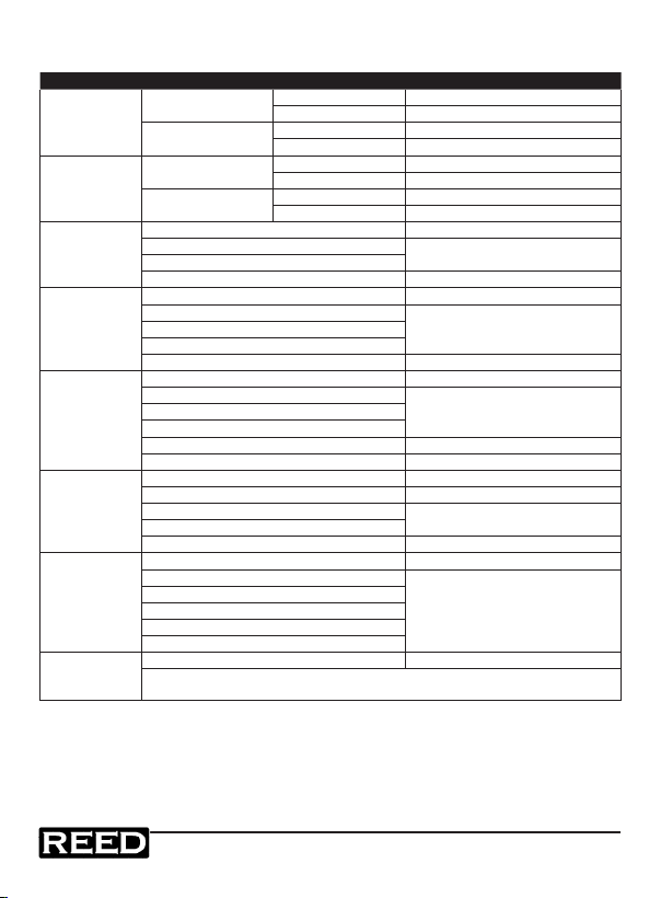
Specifications
Function Range & Resolution Accuracy (% of reading)
DC Current
40.00 ADC 0~20.00ADC ± (2.5% + 6 digits)
20.00~40.00ADC ± (3% + 6 digits)
400.0 ADC 0~300.0ADC ± (2.5% + 6 digits)
300.0~400.0ADC ± (3.5% + 6 digits)
AC Current
40.00 AAC 0~20.00AAC ± (3% + 10 digits)
20.00~40.00AAC ± (5% + 10 digits)
400.0 AAC 0~300.0AAC ± (3% + 10 digits)
300.0~400.0AAC ± (5% + 10 digits)
DC Voltage
4.000 VDC ± (0.8% + 3 digits)
40.00 VDC ± (1.5% + 3 digits)
400.0 VDC
600 VDC ± (2.0% + 3 digits)
AC Voltage
400.0 mVAC ± (1.0% + 10 digits)
4.000 VAC
± (2.0% + 5 digits)40.00 VAC
400.0 VAC
600 VAC ± (2.0% + 5 digits)
Resistance
400.0Ω ± (1.0% + 4 digits)
4.000KΩ
± (1.5% + 2 digits)40.00KΩ
400.0KΩ
4.000MΩ ± (2.5% + 3 digits)
40.00MΩ ± (3.5% + 5 digits)
Capacitance
40.00nF ±(5.0% reading + 30 digits)
400.0nF ±(3.0% reading + 5 digits)
4.000µF ±(3.5% reading + 5 digits)
40.00µF
100.0µF ±(5.0% reading + 5 digits)
Frequency
5.000Hz ±(1.5% reading + 5 digits)
50.00Hz ±(1.2% reading + 2 digits)
Sensitivity: 5~5kHz:10Vrms min.
5kHz~150kHz:40Vrms min. @ 20%
to 80% duty cycle
500.0Hz
5.000kHz
50.00kHz
150.0kHz
Duty Cycle
0.5 to 99.0% ±(1.2% reading + 2 digits)
Pulse width: 100µs - 100ms, Frequency: 5Hz to 150kHz;
Sensitivity: 5~5kHz:10Vrms min.5kHz~150kHz:40Vrms min.