reedinstruments
www com
5
Caution
• Before making measurements ensure that the function selector switch
is set on the appropriate range position.
• Always make sure that the plug of each test lead is inserted fully into
the appropriate terminal of the meter.
• Ensure that the function selector switch is set to the “OFF” position
afteruse.Whenthemeterwillnotbeinuseforalongperiodoftime,
place it in storage after removing the battery.
• Donotexposethemetertodirectsunlight,extremetemperaturesor
moisture.
• Do not use abrasives or solvents on the meter. To clean it use a damp
clothandmilddetergentonly.Onlyqualiedandtrainedservicetechni-
cians should perform calibration and repair of the meter.
ForserviceonthisoranyotherREEDproduct,contactREEDInstruments
at info@reedinstruments.com.
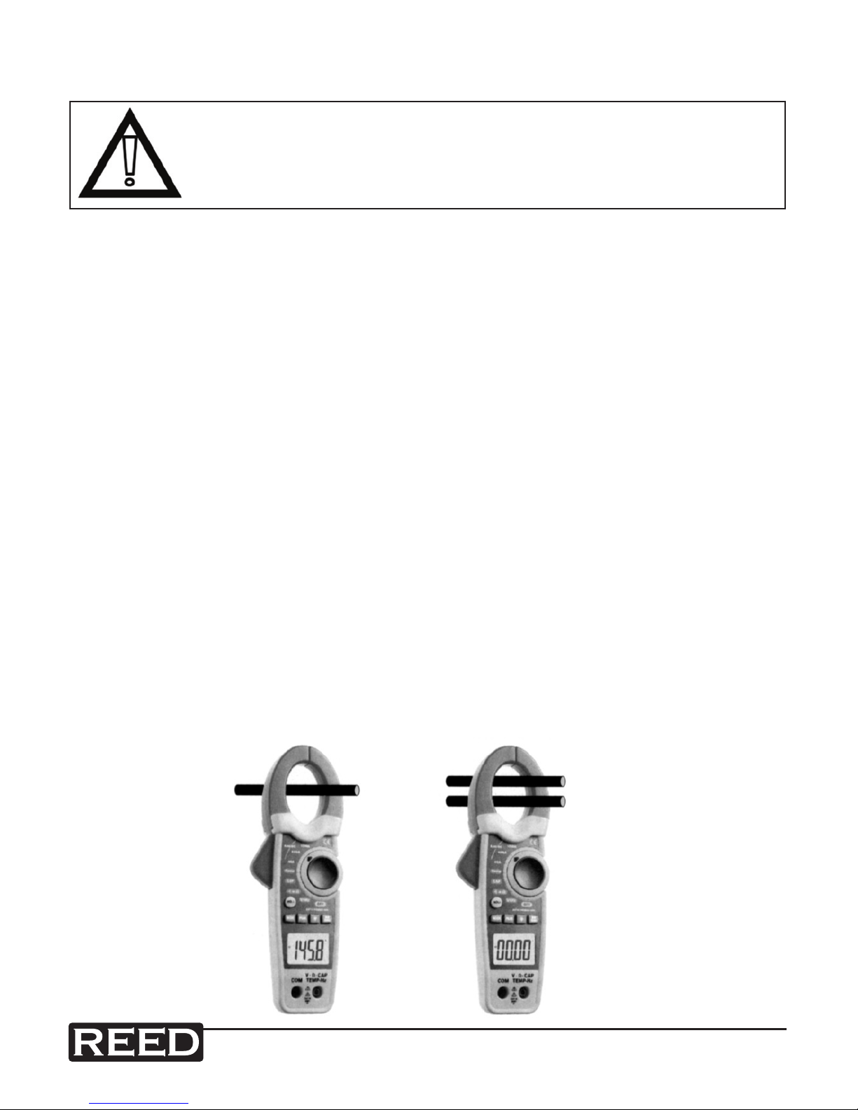
Features
• True RMS measurement of AC Current and AC Voltage
• Large 4000 count LCD display with a bargraph and a bright white LED backlight.
• Wide measuring range from 0.01A AC/DC up to 1000A AC/DC
• Measures AC and DC Voltage up to 600 volts
• Measuresresistancefrom0.01Ωupto40MΩ.
• Capacitance measurements up to 40mF
• Temperature measurements from -40°C to +1000°C and -40°F to +1832°F
• Designed to the international safety standard IEC61010 CAT III 600V /
CAT II 1000V. Pollution degree 2.
• Auto Power Off after approximately 20 minutes to conserve battery life.
• Continuity Buzzer and Diode Test.
• Frequency measurement up to 4kHz.
• Peak Hold to record the minimum and maximum readings for current & voltage.
• Data Hold switch used to freeze reading on display