2
WORK AREA
1.
Keep your work area clean and well lit. Cluttered benches
and dark areas invite accidents.
2.
Do not operate power tools in explosive atmospheres,
such as in the presence of flammable liquids, gases, or
dust. Power tools create sparks which may ignite the dust or
fumes.
3.
Keep bystanders, children, and visitors away while
operating a power tool. Distractions can cause you to lose
control.
ELECTRICAL SAFETY
1. Grounded tools must be plugged into an outlet properly
installed and grounded in accordance with all codes and
ordinances. Never remove the grounding prong or modify
the plug in any way. Do not use any adaptor plugs. Check
with a qualified electrician if you are in doubt as to
whether the outlet is properly grounded. If the tools should
electrically malfunction or breakdown, grounding provides a low
resistance path to carry electricity away from the user.
2. Avoid body contact with grounded surfaces such as pipes,
radiators, ranges and refrigerators. There is an increased
risk of electric shock if your body is grounded.
3. Don’t expose power tools to rain or wet conditions. Water
entering a power tool will increase the risk of electric shock.
4. Do not abuse the cord. Never use the cord to carry the
tools or pull the plug from an outlet. Keep cord away from
heat, oil, sharp edges or moving parts. Damaged cords
increase the risk of electric shock.
5. When operating a power tool outside, use an outdoor
extension cord marked “W-A” or “W”. These cords are
rated for outdoor use and reduce the risk of electric shock.
6. Use proper extension cords (see chart). Insufficient conduc-
tor size will cause excessive voltage drop, loss of power and
overheating.
7. Connect the tool to an AC power supply that matches the
name plate specifications. Incorrect voltage supply can
cause electrical shock or burns.
PERSONAL SAFETY
1. Stay alert, watch what you are doing and use common
sense when operating a power tool. Do not use tool while
tired or under the influence of drugs, alcohol, or medica-
tion. A moment of inattention while operating power tools may
result in serious personal injury.
2. Dress properly. Do not wear loose clothing or jewelry.
Contain long hair. Keep your hair, clothing and gloves
away from moving parts. Loose clothes, jewelry, or long hair
can be caught in moving parts.
3. Avoid accidental starting. Be sure switch is OFF before
plugging in. Carrying tools with a finger on the switch or
plugging in tools that have the switch ON invites accidents.
4. Remove adjusting keys or switches before turning the tool
on. A wrench or a key that is left attached to a rotating part of
the tool may result in personal injury.
5. Do not overreach. Keep proper footing and balance at all
times. Proper footing and balance enables better control of
the tool in unexpected situations.
6. Use safety equipment. Always wear eye protection. Dust
mask, non-skid safety shoes, hard hat, or hearing protection
must be used for appropriate conditions.
TOOL USE AND CARE
1. Use clamps or other practical methods to secure and
support the workpiece to a stable platform. Holding the
work by hand or against your body is unstable and may lead to
loss of control.
2. Do not force the tool. Use the correct tool for your applica-
tion. The correct tool will do the job better and safer at the rate
for which it is designed.
3. Do not use the tool if switch does not turn it ON or OFF.
Any tool that cannot be controlled with the switch is dangerous
and must be repaired.
4. Disconnect the plug from the power source before making
any adjustments, changing accessories, or storing the
tool. Such preventive safety measures reduce the risk of
starting the tool accidentally.
5. Store idle tools out of reach of children and other un-
trained persons. Tools are dangerous in the hands of
untrained users.
6. Maintain tools with care. Keep cutting tools sharp and
clean. Properly maintained tools, with sharp cutting edges are
less likely to bind and are easier to control.
7. Check for misalignment or binding of moving parts,
breakage of parts, and any other condition that may affect
the tool’s operation. If damaged, have the tool serviced
before using. Many accidents are caused by poorly main-
tained tools.
8. Use only accessories that are recommended by the
manufacturer for your model. Accessories that may be
suitable for one tool may become hazardous when used on
another tool.
SERVICE
1. Tool service must be performed only by qualified repair
personnel. Service or maintenance performed by unqualified
personnel could result in a risk of injury.
2. When servicing a tool, use only identical replacement
parts. Follow instructions in the Maintenance section of
this manual. Use of unauthorized parts or failure to follow
Maintenance Instructions may create a risk of electric shock or
injury.
SPECIFIC SAFETY RULES
The Operator’s Manual contains specific safety information and
instructions for your protection against serious injuries including:
•Loss of fingers, hands, arms or other body parts if clothing or
gloves get caught in moving parts.
•Electrical shock or burns from contact with wires, motor or other
power drive parts.
•Impact injuries, including broken bones if machine tips over or
workpiece falls.
•Eye injuries, including being blinded by the workpiece or
workpiece chips.
Read and follow the safety labels on the machine.
Know the location and functions of all controls before using the
tool.
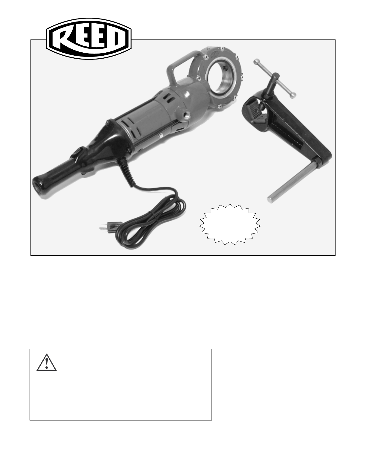
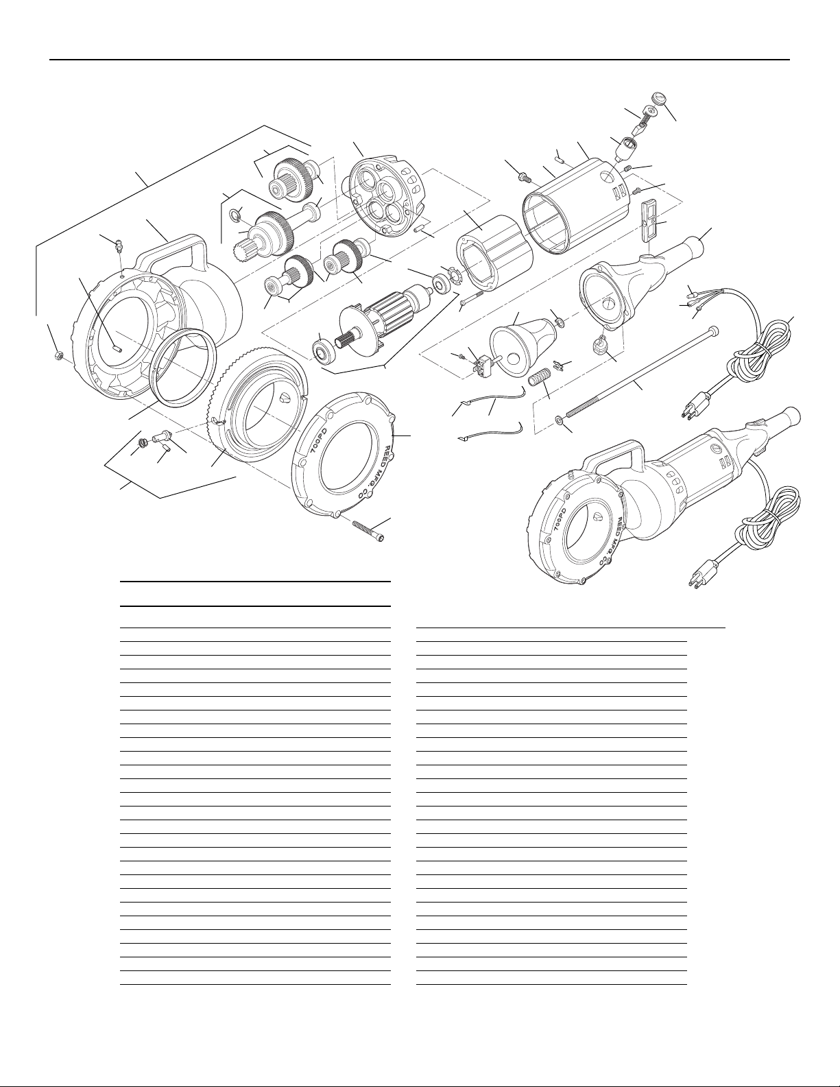
Reed Manufacturing Co.
700PD Power Drive
Minimum Wire Gauge for Cord Set
Nameplate TOTAL LENGTH (IN FEET)
Amps 0 - 25 26 - 50 51 - 100
0 - 6 18 AWG 16 AWG 16 AWG
6 -10 18 AWG 16 AWG 14 AWG
10 - 12 16 AWG 16 AWG 14 AWG
12 - 16 14 AWG 12 AWG
NOT
RECOMMENDED