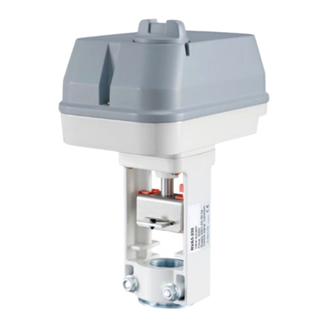
Regin RVAN18-24A User manual

INSTRUCTION
i
Read this instruction before installation
and wiring of the product
RVAN18-24A 1
Valve actuator for 0(2)...10 V control
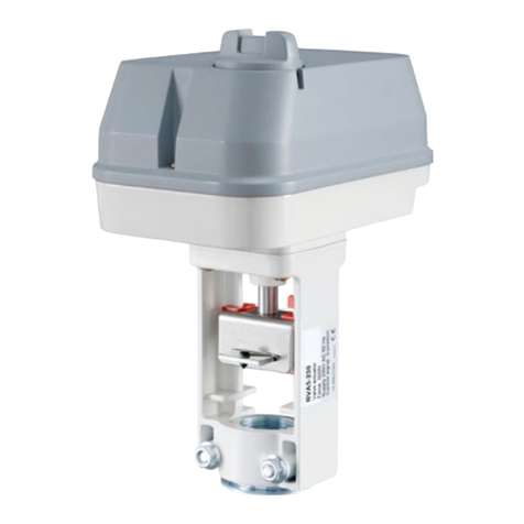
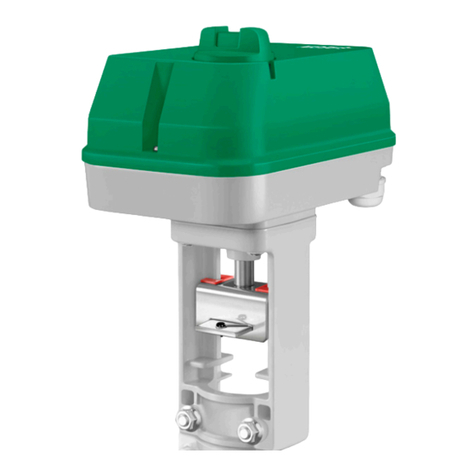
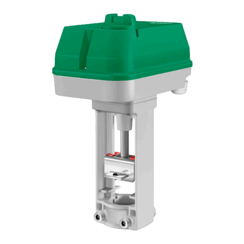
RVAN18-24A is a valve actuator designed for control of Regin valves.
The actuator has automatic self stroke adjustment and can be oper-
ated manually.
Technical data
Supply voltage 24 V AC ±15 %, 50/60 Hz
or 24 V DC ±15 %
Control signal 0(2)...10 V DC
Power consumption Max. 8 W
Stroke 10...52 mm
Stroke time 3 s/mm
Force 1800 N
Ambient temperature 0...50°C
Storage temperature -40...80°C
Ambient humidity 10...90 % RH
Dimensions (WxHxD) 198 x 309 x 133 mm
Protection class IP54
Installation
If the valve stem lock and valve throat adaptor are not already mounted
on the valve, mount them. Pull the valve stem out as far as possible.
Remove the screws (hex key 6 mm) and clamp from the actuator yoke.
Depress the spring-loaded tab on the drive rod coupling device and t the
valve stem into the coupling.
Release the tab to connect the valve to the actuator. The position of the
yoke on the valve stem adaptor must be adjusted so that the clamp screw
holes line up with the groove in the valve throat adaptor. If the drive rod
needs to be moved in or out for this, depress the central button of the
control knob and turn it clockwise to extend the drive rod and counter-
clockwise to retract it (see Manual override). Mount the screws and the
clamp. Tighten the screws until the actuator is rmly attached.
Disassembly takes place in reverse order.
Mounting positions
90º
90º
Wiring
24 V AC/DC
1 2 3 4 5
12345 6
Override input
Y 0(2)...10 V DC
Control signal from
controller
U 0...10 V DC
Measuring voltage
for position indication
Signal neutral
YU B
MG0 G
Stroke and end position calibration
Stroke and end position calibration is not necessary due to a con-
struction utilizing end position stops. When the valve reaches the end
position, a force is generated. Once the force of the actuator reaches
a predened level, the limit switch automatically halts the drive motor.
Override
Activation of the override input will force the valve to the maximum
open position.
Manual override
To manually set the valve position, rst depress the central part of the
knob, until it clicks and remains depressed (1 in the gure). Then the
valve position can be changed manually by turning the knob (2 in the
gure). When the knob is turned clockwise, the drive rod is pushed
outwards and when the knob is turned anti-clockwise, the drive rod is
pulled inwards.
To return to normal operation, set the knob so that it is in line with the
text ”Auto” on the cover. Then depress the outer parts of the knob (3
in the gure). The central depressed part will pop out, and the actua-
tor will return to normal operation.
Note: After any manual operation the actuator will always run through
a zero point calibration.
DIP switches
There are ve DIP switches for setting different functions. Follow the
table below for setting the DIP switches.
Adjusted settings will be valid only after the next power-on.
RVAN18-24A
10578A
SEP 13
EN

RVAN18-24A 2
1 (On) 0 (Off)
SW1 Spindle down when the
valve is closed
Spindle up when the valve is
closed (FS=factory setting)
SW2 Y = 2...10 V DC Y = 0...10 V DC (FS)
SW3 Reverse operation Direct operation (FS)
SW4 Y signal split in accordance
with the setting of SW5
No split function (FS)
SW5 5(6)...10 V = 0...100 % 0(2)...5(6) V = 0...100 % (FS)
SW1 Operational direction of the valve
On: The valve is closed when the stem is in its lowest position.
Off: The valve is closed when the stem is in its highest position.
SW2 Control signal
On: 2...10 V DC
Off: 0...10 V DC
The actuator can also be connected to a 4...20 mA control signal.
In this case, a 500 Ohm resistor should be installed between the
control signal input (terminal 3) and system neutral (terminal 2)
and SW2 should be set to position On (2...10 V DC).
The control signal will then be converted to 2...10 V DC.
SW3 Reverse/Direct operation
On: Reverse operation. The actuator closes the valve on increasing
control signal.
Off: Direct operation. The actuator opens the valve on increasing
control signal.
SW4 Split function
On: Split function. Two actuators can share a control signal and work
in sequence.
Off: No split function.
SW5 Working range when using split function
On: 5…10 V= 0…100 % (6…10 V when SW2=On)
Off: 0…5 V= 0…100 % (2…6 V when SW2=On)
LEDs
The actuator has two LEDs with indications according to the table below.
Indication
Green steady light Actuator working properly
Green light quick ashing Test run in progress
Green light slow ashing The setting was changed during the
operation. The new setting will be
valid after the next power on.
Red and green steady light End position reached
Red light slow ashing Override operating mode
Red steady light Operation faulty, either the improper
installation or the valve stroke lost
End position markers
There is a red and a blue plastic end position marker on the actuator
linkage. The markers can easily be moved in order to show when the
actuator is closed/open for heating/cooling.
For heating valves, the red marker should be in the completely open valve
position and the blue marker in the completely closed valve position.
For cooling valves, the blue marker should be in the completely open
valve position and the red marker in the completely closed valve position.
EMC emissions & immunity standards
This product conforms to the requirements of the EMC Directive
2004/108/EC through product standards EN 60730-1:2000 and
EN 60730-2-14:1997.
RoHS
This product conforms with the Directive 2011/65/EU of the European
Parliament and of the Council.
Contact
AB Regin, Box 116, 428 22 Kållered, Sweden
Tel: +46 31 720 02 00, Fax: +46 31 720 02 50
www.regincontrols.com, [email protected]
Ventilställdon för 0(2)...10 V-styrning
RVAN18-24A är ett ventilställdon för styrning av Regins ventilsorti-
ment. Ställdonet har automatisk slaglängdsjustering och går att styra
manuellt.
Tekniska data
Matningsspänning 24 V AC ±15 %, 50/60 Hz
eller 24 V DC ±15%
Styrsignal 0(2)...10 V DC
Effektförbrukning Max. 8 W
Slaglängd 10...52 mm
Ställtid 3 s/mm
Ställkraft 1800 N
Omgivningstemperatur 0...50°C
Lagringstemperatur -40...80°C
Omgivande luftfuktighet 10...90 % RH
Dimensioner (BxHxD) 198 x 309 x 133 mm
Skyddsklass IP54
Installation
Om spindeltopp och ventilhalsadapter inte redan är monterade på
ventilen, montera dem. Dra ut ventilspindeln så långt det går.
Ta bort skruvarna (insexnyckel 6 mm) och klämman från ställdonets
ok.
Tryck in den fjädrande brickan på drivspindelns kopplingsanordning
och passa in spindeltoppen i kopplingen.
Släpp brickan för att koppla ventilen till ställdonet. Okets läge på ven-
tilhalsadaptern justeras så att klämmans skruvhål kommer i linje med
spåret på ventilhalsadaptern. Om drivspindeln behöver yttas in eller
ut för att detta ska ske, tryck ned mittknappen på manöverratten och
vrid denna medurs för att ytta ut spindeln och moturs för att ytta in
spindeln (se Manuell överstyrning). Montera skruvarna och klämman.
Dra åt skruvarna så att ställdonet sitter stadigt fast.
Nedmontering i omvänd ordning.
i
INSTRUKTION
RVAN18-24A
SV
Läs denna instruktion innan produkten monteras
och ansluts
RVAN18-24A 3
Monteringspositioner
90º
90º
Inkoppling
1 2 3 4 5
12345 6
Överstyrningsingång
Y 0(2)...10 V DC
Styrsignal från
regulator
U 0...10 V DC
Mätspänning för
lägesindikering
24 V AC/DC
Signal neutral
YU B
MG0 G
Slaglängds- och ändlägeskalibrering
Slaglängds- och ändlägeskalibrering är ej nödvändig på grund av en
konstruktion med inbyggda ändlägesbrytare. En ställkraft byggs upp
när ventilen når ändläget. När ställkraften uppgår till den inställda
nivån stoppar en brytare automatiskt drivmotorn.
Överstyrning
När överstyrningsingången aktiveras tvingas ventilen till maximalt
öppet läge.
Manuell överstyrning
För att manuellt ställa in ventilpositionen, tryck först ned mittknappen på
ratten tills den klickar och stannar kvar i nedtryckt läge (1 i guren). Ventil-
positionen kan då ändras manuellt genom att vrida på ratten (2 i guren).
Vid medurs vridning skjuts drivstången utåt och vid moturs vridning dras
den inåt.
För att återgå till normal drift, ställ ratten i linje med texten ”Auto” på
locket. Tryck sedan ned de yttre delarna av ratten (3 i guren). Mittknap-
pen kommer att hoppa upp och ställdonet återgår till normal drift.
OBS: Efter manuell hantering genomför ställdonet alltid en fullständig
nollpunktskalibrering.
DIP-switchar
Det nns fem DIP-switchar för att ställa in olika funktioner. Följ tabellen
nedan för inställning av dipswitcharna.
Nya inställningar kommer att gälla först efter nästa spänningstillslag.
1 (On) 0 (Off)
SW1 Spindel ned vid stängd
ventil
Spindel upp vid stängd ventil
(FI=fabriksinställning)
SW2 Y = 2...10 V DC Y = 0...10 V DC (FI)
SW3 Omvänd verkan Direkt verkan (FI)
SW4 Y-signalsplit enligt
inställning av SW5
Ingen splitfunktion (FI)
SW5 5(6)...10 V = 0...100 % 0(2)...5(6) V = 0...100 % (FI)
SW1 Ventilens arbetsriktning
On: Ventilen är stängd när spindeln är i sitt nedre läge.
Off: Ventilen är stängd när spindeln är i sitt övre läge.
SW2 Styrsignal
On: 2...10 V DC
Off: 0...10 V DC
Det går även att ansluta ställdonet till 4...20 mA styrsignal.
I detta fall ska ett 500 Ohm motstånd monteras mellan
ingången för styrsignal (plint 3) och systemnoll (plint 2)
och SW2 ställas i läge On (2...10 V DC).
Styrsignalen kommer då att omvandlas till 2...10 V DC.
SW3 Omvänd/Direkt verkan
On: Omvänd verkan. Ställdonet stänger ventilen vid ökande
styrsignal.
Off: Direkt verkan. Ställdonet öppnar ventilen vid ökande
styrsignal.
SW4 Splitfunktion
On: Splitfunktion. Två ställdon kan dela styrsignal och arbeta
i sekvens.
Off: Ingen splitfunktion.
SW5 Arbetsområde vid splitfunktion
On: 5…10 V= 0…100 % (6…10 V då SW2=On)
Off: 0…5 V= 0…100 % (2…6 V då SW2=On)
Lysdioder
Ställdonet har två lysdioder med indikeringar enligt nedanstående
tabell.
Indikering
Fast grönt ljus Ställdonet fungerar ordentligt
Grönt ljus som blinkar snabbt Provkörning pågår
Grönt ljus som blinkar långsamt Inställningen ändrades under
körning. Nya inställningar kom-
mer att gälla först efter nästa
spänningstillslag.
Fast rött och grönt ljus Ändläget har nåtts
Rött ljus som blinkar långsamt Driftläget överstyrs
Fast rött ljus Felaktigt handhavande, an-
tingen var installationen felaktig
eller så gick ventilens slaglängd
förlorad

RVAN18-24A 4
i
ANLEITUNG
RVAN18-24A
DE
Diese Anleitung vor Montage und Anschluss
des Produktes bitte durchlesen
Ventilstellantrieb für 0(2)...10 V-Ansteuerung
RVAN18-24A ist ein Stellantrieb für die Ansteuerung von Regin Ventilen.
Der Stellantrieb ist mit automatischer Hubanpassung und Handbedienung
ausgestattet.
Technische Daten
Versorgungsspannung 24 V AC ±15 %, 50/60 Hz,
oder 24 V DC ±15 %
Stellsignal 0(2)...10 V DC
Leistungsaufnahme Max. 8 W
Hubweg 10...52 mm
Laufzeit 3 s/mm
Stellkraft 1800 N
Umgebungstemperatur 0...50ºC
Lagertemperatur -40...80°C
Umgebungsfeuchte 10...90 % rel.F.
Abmessungen (BxHxT) 198 x 309 x 133 mm
Schutzart IP54
Installation
Ventiladapter und Spindeladapter anbringen, falls sie noch nicht am Ventil
montiert sind. Dazu den Ventiladapter mittels der beigelegten Schrauben
(mit Imbussschlüssel 6 mm) auf dem Ventil befestigen.
Jetzt die Ventilspindel so weit wie möglich herausziehen und den
Spindeladapter mit Kontermutter auf der Ventilspindel montieren.
Arretierungsklemme vom Stellantrieb entfernen.
Die Kupplungsplatte der Antriebsstange drücken und gleichzeitig die
Ventilspindel in die große Öffnung einfügen.
Zum Einrasten Knopf loslassen. Jetzt die Antriebskonsole soweit
drehen, bis sich die Bohrung der Arretierungsklemme und die Nut des
Ventiladapters auf gleicher Position benden. Sollte die Antriebsstange
hierfür bewegt werden müssen, ist der mittlere Teil des Steuerknopfs zu
drücken und zu drehen (im Uhrzeigersinn bewegt die Antriebs-stange
nach unten, gegen den Uhrzeigersinn nach oben). Schrauben und Ar-
retierungsklemme anbringen. Schrauben anziehen bis der Stellantrieb
fest montiert ist.
Demontage erfolgt in umgekehrter Reihenfolge.
Ändlägesmarkeringar
Det nns en röd och en blå ändlägesmarkering i plast på ställdonets
stativ. Markeringarna kan enkelt yttas för att visa när ställdonet är
stängt/öppet för värme/kyla.
Vid värmeventil ska den röda markeringen vara i läget för helt öppen
ventil och den blå markeringen i läget för helt stängd ventil.
Vid kylventil ska den blå markeringen vara i läge för helt öppen ventil
och den röda markeringen i läge för helt stängd ventil.
EMC emissions- och immunitetsstandard
Produkten uppfyller kraven i EMC-direktivet
2004/108/EG genom produktstandarder EN 60730-1:2000 och EN
60730-2-14:1997.
RoHS
Produkten uppfyller Europaparlamentets och rådets direktiv 2011/65/
EU.
Kontakt
AB Regin, Box 116, 428 22 Kållered
Tel: +46 31 720 02 00, Fax: +46 31 720 02 50
www.regin.se, [email protected]
Einbaulagen
90º
90º
Anschluss
24 V AC/DC
1 2 3 4 5
12345 6
Override input
Y 0(2)...10 V DC
Control signal from
controller
U 0...10 V DC
Measuring voltage
for position indication
Signal neutral
YU B
MG0 G
Hubweg- und Enpunktkalibrierung
Eine Hubweg- und Endlagenkalibrierung wird nicht benötigt, da bei
Erreichen der Endlage eine Stellkraft generiert wird. Erreicht diese ein
vorbestimmtes Niveau, stoppt ein Endlagenschalter automatisch den
Antriebsmotor.
Übersteuerung
Bei Aktivierung des Übersteuerungseingangs wird das Ventil
zwangsweise ganz geöffnet.

RVAN18-24A 5
Handbedienung
Die Ventilstellung kann manuell eingestellt werden, indem der mittlere
Teil des Drehknopfes heruntergedrückt wird, bis er einrastet (1 in der
Abbildung). Danach kann die Ventilstellung durch Drehen des Knopfes
verstellt werden (2 in der Abbildung). Im Uhrzeigersinn wird die
Antriebsstange nach unten, und gegen den Uhrzeigersinn nach oben
bewegt.
Für erneuten Normalbetrieb den Knopf drehen, bis er in einer Linie mit
dem Text „Auto“ (auf dem Gehäuse) ist. Danach auf den äußeren Rand
des Knopfes drücken (3 in der Abbildung). Der mittlere Teil wird dann
entsperrt, und der Stellantrieb schaltet wieder in Normalbetrieb um.
Hinweis: Nach Handbedienung wird der Stellantrieb immer den Nullpunkt
abgleichen.
DIP-Schalter
Der Stellantrieb verfügt über 5 DIP-Schalter zur Einstellung ver-
schiedener Funktionen. In der folgenden Tabelle werden die Ein-
stellungen der DIP-Schalter beschrieben.
Änderungen der Einstellungen sind erst ab dem nächsten Einschalten
gültig.
1 (On) 0 (Off)
SW1 Schließpunkt unten Schließpunkt oben
(WE=Werkseinstellung)
SW2 Y = 2...10 V DC Y = 0...10 V DC (WE)
SW3 Invertierte Stellrichtung Normale Stellrichtung (WE)
SW4 Y-Signal-Splittung entspre-
chend Einstellung an SW5
Keine Splittung (WE)
SW5 5(6)...10 V = 0...100 % 0(2)...5(6) V = 0...100 % (WE)
SW1 Wirkrichtung des Ventils
On: Das Ventil ist geschlossen, wenn sich die Spindel in der niedrigsten
Position bendet.
Off: Das Ventil ist geschlossen, wenn sich die Spindel in der höchsten
Position bendet.
SW2 Stellsignal
On: 2...10 V DC
Off: 0...10 V DC
Der Stellantrieb kann auch mit einem 4...20 mA-Stellsignal angesteuert
werden. In diesem Falle ist ein 500-Ω-Widerstand zwischen Stellsignale-
ingang (Kl. 3) und Neutralleiter (Kl. 2) anzubringen, und SW2 muss auf
On (2...10 V DC) stehen. Dann wird das Stellsignal vom Regler in 2...10 V
DC umgewandelt.
SW3 Invertierte / normale Stellrichtung
On: Invertierte Stellrichtung. Bei ansteigendem Stellsignal schließt der
Stellantrieb das Ventil.
Off: Normale Stellrichtung. Bei ansteigendem Stellsignal öffnet der
Stellantrieb das Ventil.
SW4 Splittung
On: Splittung. Ein Stellsignal wird auf zwei Stellantriebe aufgeteilt, die
nacheinander arbeiten.
Off: Keine Splittung.
SW5 Arbeitsbereich bei Splittung
On: 5…10 V= 0…100 % (6…10 V wenn SW2=On)
Off: 0…5 V= 0…100 % (2…6 V wenn SW2=On)
LEDs
Der Stellantrieb ist mit einer roten und einer grünen LED ausge-stattet,
die Folgendes anzeigen:
Anzeige
Stetiges grünes Licht Stellantrieb funktioniert fehlerfrei
Grünes, schnell blinkendes
Licht
Testlauf
Grünes, langsam blinkendes
Licht
Einstellungen während des Testlaufs
geändert. Die neuen Einstellungen
sind ab dem nächsten Einschalten
gültig.
Stetiges rotes und grünes
Licht
Endlage erreicht
Rotes, langsam blinkendes
Licht
Betriebsmodus Übersteuerung
Stetiges rotes Licht Fehlfunktion; entweder inkorrekte
Installation oder fehlender Hubweg
Endlagenanzeige:
An der Konsole des Stellantriebs benden sich eine rote und eine
blaue Endlagenmarkierung. Diese Markierungen können einfach
verschoben werden, um anzuzeigen, wann das Ventil zum Heizen/
Kühlen offen/geschlossen ist.
Bei Heizventilen sollte die rote Markierung die offene Endlage, und
die blaue Markierung die geschlossene Endlage anzeigen.
Bei Kühlventilen sollte die blaue Markierung die offene Endlage, und
die rote Markierung die geschlossene Endlage anzeigen.
Elektromagnetische Verträglichkeit
Dieses Produkt entspricht den Anforderungen der EMV-Richtlinie
2004/108/EG durch Erfüllung der Normen EN 60730-1:2000 und EN
60730-2-14:1997.
RoHS:
Dieses Produkt entspricht den Anforderungen der Richtlinie 2011/65/
EU des europäischen Parlamentes und des Rates.
Kontakt
RICCIUS + SOHN GmbH Vertriebsbüro Deutschland, Haynauer Str.
49, 12249 Berlin Tel: +49 30 77 99 40, Fax: +49 30 77 99 413 info@
riccius-sohn.eu, www.regincontrols.de

RVAN18-24A 6
i
Veuillez lire cette instruction avant de procéder
à l’installation et au raccordement de l’appareil.
INSTRUCTION
RVAN18-24A
FR
Moteur de vanne pour contrôle 0(2)...10 V
L’actionneur RVAN18-24A est prévu pour le pilotage de vannes
Regin. L’ajustement de la course est automatique. Le moteur dispose
d’une commande manuelle.
Caractéristiques techniques
Tension d’alimentation 24 V AC ±15 %, 50/60 Hz,
ou 24 V DC ±15 %
Signal de commande 0(2)...10 V DC
Puissance consommée 8 W max.
Course 10...52 mm
Temps de course 3 s/mm
Force 1800 N
Température ambiante 0...50ºC
Température de stockage -40...80°C
Humidité ambiante 10...90 % HR
Dimensions (LxHxP) 198 x 309 x 133 mm
Indice de protection IP54
Installation
Si ce n’est pas déjà fait, montez l’écrou de blocage de la tige et
l’adaptateur sur la vanne. Tirez la tige au maximum.
À l’aide d’une clé de 10, retirez les vis et l’attache de l’actionneur.
Appuyez sur le ressort du dispositif d’attache de la tige, et insérez la
tige de la vanne.
Lâchez le ressort pour raccorder la vanne à l’actionneur. An que les
trous pour les vis de l’attache soient alignés avec l’axe à l’intérieur
de l’adaptateur, ajustez la position de l’actionneur sur l’adaptateur
de la vanne. Si vous avez besoin de faire rentrer ou sortir la tige
d’actionnement pour réaliser cette opération, appuyez sur la partie
centrale du bouton de commande manuelle. Ensuite, tournez le dans
le sens des aiguilles d’une montre pour faire sortir la tige, ou dans le
sens inverse pour la faire rentrer (voir Commande manuelle). Montez
l’attache et les vis. Vissez jusqu’à ce que l’actionneur soit fermement
xé sur la vanne.
Pour démonter l’actionneur, suivez les instructions précédentes dans
le sens inverse.
Positions de montage
90º
90º
Raccordement
24 V AC/DC
1 2 3 4 5
12345 6
Y 0(2)...10 V DC
U 0...10 V DC
Signal neutre
Signal de commande
du régulateur
Tension de mesure
pour l’indicateur
de position
Entrée forçage
YU B
MG0 G
Étalonnage de la course et des limites
L’étalonnage de la course et des limites n’est pas nécessaire grâce à
la présence de butées. Lorsque la vanne atteint la butée, elle rencontre
une résistance. Une fois que la force de l’actionneur a atteint un niveau
prédéni, l’interrupteur de limitation coupe automatiquement le moteur.
Forçage
L’utilisation de l’entrée de forçage permet de commander la vanne en
position complètement ouverte.
Commande manuelle
Pour régler manuellement la position de la vanne, appuyez sur la
partie centrale du bouton jusqu’à entendre un clic. Elle doit rester
enfoncée (nº1 sur le schéma ci-dessus). Il est alors possible de
modier manuellement la position du boisseau en tournant le bouton
(nº2 sur le schéma ci-dessus). Tournez dans le sens des aiguilles
d’une montre pour faire sortir la tige d’actionnement, ou dans le sens
inverse pour la faire rentrer.
Pour revenir en mode normal, repositionnez le bouton an qu’il soit
aligné avec le texte « Auto ». Appuyez sur les côtés du bouton (nº3
sur le schéma ci-dessus). La partie centrale se débloque et retourne
en position normale (non enfoncée). L’actionneur fonctionne de nou-
veau automatiquement.
Note : Après chaque manœuvre manuelle, le point zéro est étalonné
automatiquement.
Interrupteurs DIP
Les différentes fonctions de l’actionneur peuvent être congurées
grâce à cinq interrupteurs DIP. Voir le tableau ci-dessous pour plus de
détails.
Les nouveaux réglages prendront effet à la prochaine mise sous
tension.
1 (ON) 0 (OFF)
SW1 La tige est en bas lorsque
la vanne est fermée
La tige est en haut lorsque
la vanne est fermée (RU =
Réglage usine)
SW2 Y = 2...10 V DC Y = 0...10 V DC (RU)
SW3 Action inversée Fonctionnement direct
SW4 Split signal Y selon le rég-
lage de SW5
Pas de fonction de split (RU)
SW5 5(6)...10 V = 0...100 % 0(2)...5(6) V = 0...100 % (RU)

RVAN18-24A 7
SW1 Direction opérationnelle de la vanne
On : La vanne est fermée lorsque la tige est poussée à fond, c.-à-d. dans
sa position la plus basse.
Off : La vanne est fermée lorsque la tige est tirée à fond, c.-à-d. dans
sa position la plus haute.
SW2 Signal de commande
On : 2...10 V DC
Off : 0...10 V DC
L’actionneur peut aussi fonctionner avec un signal 4...20 mA.
Dans ce cas, une résistance de 500 Ω doit être raccordée entre
l’entrée du signal de commande (borne 3) et le neutre (borne 2).
SW2 doit être réglé sur On (2...10 V DC). Le signal de commande
4...20 mA est alors converti en un signal 2...10 V DC.
SW3 Course directe/inversée
On : Action inversée. L’actionneur ferme la vanne quand le signal de
commande augmente.
Off : Fonctionnement direct. L’actionneur ouvre la vanne quand le signal
de commande augmente.
SW4 Fonction split
On : Fonction split active. Deux actionneurs peuvent partager un même
signal de commande et travailler en séquence.
Off : Fonction split inactive.
SW5 Plage de fonctionnement avec la fonction split
On : 5…10 V= 0…100 % (6…10 V quand SW2=On)
Off : 0…5 V= 0…100 % (2…6 V quand SW2=On)
Indications
Le moteur est équipé de deux LEDs dont la signication est décrite dans
le tableau ci-dessous.
Indication
Voyant vert xe L’actionneur fonctionne correctement
Voyant vert clignotant
rapidement
Test en cours
Voyant vert clignotant
lentement
Le réglage a été changé pendant le
fonctionnement. Le nouveau réglage
prendra effet à la prochaine mise
sous tension.
Voyants rouge et vert
allumés xes
Fin de course atteinte
Voyant rouge clignotant
lentement
Commande forcée
Voyant rouge xe Erreur de fonctionnement (montage
incorrect ou étalonnage de course
perdu).
Repères de n de course
Deux repères en plastique (un rouge et un bleu) permettent de marquer
les positions de n de course de l’actionneur. Ils peuvent également être
déplacés an de marquer la position ouverte/fermée de l’actionneur pour
le chauffage/refroidissement.
Avec une vanne de chauffage, utilisez le repère rouge pour
marquer la position de la vanne lorsqu’elle est totalement ouverte et le
marqueur bleu pour marquer sa position lorsqu’elle est totalement fermée.
Avec une vanne de refroidissement, utilisez le repère bleu pour marquer
la position de la vanne lorsqu’elle est totalement ouverte et le marqueur
rouge pour marquer sa position lorsqu’elle est totalement fermée.
Directive compatibilité électromagnétique (CEM)
Ce produit répond aux exigences de la directive 2004/108/CE du Parle-
ment européen et du Conseil (CEM) au travers de la conformité aux
normes EN 60730-1:2000 et EN 60730-2-14:1997.
RoHS
Ce produit répond aux exigences de la directive 2011/65/UE du
Parlement européen et du Conseil.
Contact
Regin FRANCE, 32 rue Delizy, 93500 Pantin
Tél : +33(0)1 71 00 34, Fax : +33(0)1 71 46 46
www.regin.fr, [email protected]
Table of contents
Languages:
Other Regin Controllers manuals

Regin
Regin TTC80F User manual

Regin
Regin CORRIGO L10 User manual

Regin
Regin OPTIGO OP10 User manual

Regin
Regin REGIO RC-DTO User manual

Regin
Regin RVAPC-24A User manual

Regin
Regin Corrigo User manual

Regin
Regin TTC40FX User manual

Regin
Regin TT-S4/D User manual

Regin
Regin AQUA230T User manual

Regin
Regin TTC 2000 User manual

Regin
Regin RCF Series User manual

Regin
Regin HR1-DH User manual

Regin
Regin RCF-230CTD-EC User manual

Regin
Regin ALC230A User manual

Regin
Regin RVAR5-24A User manual

Regin
Regin REGIO ARDO User manual

Regin
Regin Corrigo U10 Series User manual

Regin
Regin SPINN/D User manual

Regin
Regin RVASM16 User manual

Regin
Regin RDAS7S-24C User manual