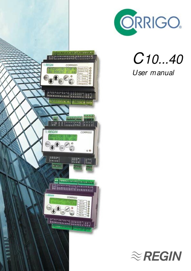
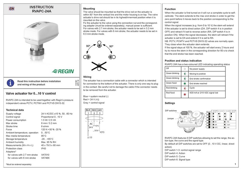
Regin Corrigo C10-LON User manual

2418C JAN 00 1.5.5
CORRIGO C10-LON INSTRUCTION
Corrigo C10-LON is a controller primarily intended
for controlling air handling units. It can easily be
adapted to suit different types of units.
Corrigo C10-LON has built-in capability for LON
communication. See separate LON interface manual.
Corrigo C10-LON has three 0...10 V DC control outputs
in sequence for controlling for example heating / heat
exchanger / cooling.
It has a number of functions and possibilities, such as
DX-cooling in one or two steps, outdoor temperature
compensation, fire damper exercise, control and
monitoring of fans and circulation pump, free cooling,
heat-exhanger efficiency calculation etc.
Corrigo C10-LON can also receive and handle a number
of alarms such as fan and filter alarm, smoke alarm,
chiller alarm, heat-exchanger alarm and has a free relay
output for total alarm.
Corrigo C10-LON has a year-base real-time clock,
week-scheduler , holiday calendar, holiday periods and
automatic normal time/daylight saving time change-over.
Installation
Mount the unit on a DIN rail in a cabinet or separate
enclosure.
For mounting in the cabinet front, use mounting kit FMC.
Degree of protection IP20
Ambient temperature 0...50°C
Wiring
Supply voltage
Terminals 42 and 43: 24 V AC, ±15%, 50/60 Hz.
Sensors AI3...AI8
Use PT1000 sensors. (See data sheet 4-150).
The choice of which sensors to connect is determined by
the choice of functions. The table, fig 3 can be used as
an aid in determining which sensors to install.
Connect the sensors according to the terminal schema-
tics on page 6.
N.B. All AI-inputs must refer to the signal neutral termin-
als for AI-inputs (terminals 24, 27, 30, 33).
AI4 has different functions depending on settings.
1. Efficiency calculation - exhaust air sensor.
2. Liquid-connected heat exchanger - limiting sensor in
the exchanger circulation system.
3. External setpoint. Input for setpoint signal.
These functions are mutually exclusive.
Only one of them may be chosen.
AI8 is, depending on setting, used for:
1. Frost protection sensor for applications with water
heated heater.
2. High temperature limiting switch for applications with
electrical heater.
When used for high temperature limiting switch it must be
connected to a free contact closing on alarm.
Fan supervision,
supply air fan, exhaust air fan AI1, AI2
Connect AI1 and AI2 to free contacts that open when the
fans stop.
Either in form of pressure switches monitoring the
pressure over each fan or as free contacts in the fan
motor relays.
N.B. Since these signals control vital functions they must
be connected for the unit to work as intended.
Digital inputs DI1...DI8
The digital inputs DI1...DI8 must refer to terminal 22.
N.B. Terminal 22 must not be connected to any other
terminals but should only be used as reference for units
connected to DI1...DI8.
The inputs may only be connected to potential free
contacts.
Closed contact activates alarm or function.
Unused inputs are to be left open.
DI1 Input for filter guards
DI2 Input for circulation pump indication.
Must be connected for systems with water heating.
DI3 Input for chiller alarm
DI4 Input for rotation sentinel or ice build-up sentinel for
heat exchanger.
DI5 Input for smoke alarm.
DI6 Input for fire damper end-position indication, external
alarm or external switches ”not in Auto position”.
(See textblock on DO6/DI6 on page 6).
DI7 Input for start of extended running time for single
speed fan systems or high speed for two speed fan
systems.
DI8 Input for start of extended running time at low speed
for two speed fan systems
DI7 and DI8 should, depending on settings, either be
wired to a momentarily closing pushbutton or to, for
example, a timer.
If DI7 and DI8 are both closed at the same time the unit is
shut down.
If a separate handswitch for setting the running mode is
installed it should be wired according to figure 1 or 2.
!
IMPORTANT: Read these
instructions before installation
and wiring of the product.
1-speed fans 2-speed
INSTRUCTION 1
ð
Fig 3
Fig 1
High
Low
0
Auto
DI7
DI8
H
0
Auto
DI8
DI7
Fig 2
Tel:+46 (0)31 795 44 60 Fax:+46 (0)31 795 38 50
Box 116
428 22 KÅLLERED, SWEDEN

2418C JAN 00 1.5.5
CORRIGO C10-LON INSTRUCTION
Analogue 0...10 V DC control outputs, AO1, AO2,
AO3
Output signal 0...10 V DC, 5 mA. Short circuit proof.
AO1 Control output Y1
AO2 Control output Y2
AO3 Control output Y3
These outputs must refer to terminal 41, Signal neutral.
Since signal neutral in the Corrigo is galvanically
separated from system neutral the signal neutral from
the actuator must be connected to terminal 41 even if
the actuator and the Corrigo share a common trans-
former.
The function of the different outputs depends on the
configuration settings but the sequence order will always
be Y3 àY2 àY1 on increasing heat demand.
Other control outputs, DO1...DO7
The digital outputs DO1...DO6 are triac controlled.
0,5A, 24 V AC. Short term peak load 1A.
Output DO7 is a potential free relay contact.
The outputs are paired to 24 V AC supply inputs. (See
terminal schematics, page 6).
For higher voltages and currents use relay modules
RM6-24/D or RM6H-24/D that are specially designed for
use with Corrigo.
Some of the outputs have alternative functions
depending on the system configuration. This means for
example, that DX cooling cannot be combined with
control of two-speed fans.
DO1Control supply air fan or supply air fan high speed
for two-speed fans.
DO2Control exhaust air fan or exhaust air fan high
speed for two speed fans.
DO3Control circulation pump or for electric heating
interlocking.
DO4Control DX-chiller 1or supply air fan low speed for
two-speed fans.
DO5Control DX-chiller 2 or exhaust air fan low speed for
two speed fans.
DO6Ecternal frost protection or fire damper exercising.
(See text section DO6/DI6 page 6).
DO7Potential free relay contact for alarm output.
1 A, 24 V AC/DC. Closes on alarm.
Buttons and display
Language
The menu text language can be changed.
Hold the !button depressed during power up to enter the
setup mode. Then press !again and a blinking marker will
appear next to the current language. Select the desired
language by using the arrow buttons. When the marker is
next to the desired language, press OK. Press OK again
to return to the normal menu system.
All information that can be shown on the display is
organised in menues in a ”menu-tree”.
Using the buttons on the front you can move between the
different menues in the tree, look at parameters, change
settings, display and reset alarms.
What you can see and do is governed by your log-on
level.
The ”Trunk” of the menu-tree contains the following
menues:
Logon
Configuration Only shown in level 3
Control temp ïStarting point
Running mode
AI Analogue in
DI Digital in
AO Analogue out
DO Digital out
Scheduler
Alarm settings Not shown in level 0
Settings Only shown in level 2 and 3
During normal running when the buttons are not in use a
series of menu pages is shown.
The display alternates between, a general display with
product description and clock, setpoint/actual tempera-
ture, and output status for the control outputs Y1, Y2, Y3.
To gain access to the menu-tree press OK and the
display will change to Control temp.
By pressing éand êyou can move up and down the
tree. The arrows to the right in the display indicate
whether there are menu pages above or below the one
shown.
>Temp control á
AI Analogue in â
To move out onto any of the ”branches” press OK. Out on
the branch you can then move about in the same way
using the arrowbuttons. By pressing Esc you can jump
back towards the trunk.
In menu pages with settable parameters you shift to
”Setting mode” by pressing !.
A dark blinking marker will then appear in the first settable
position. By using the arrow buttons the value can be
changed. When the correct value is shown press OK and
the marker will move to the next position. After OK on the
last position the new value is stored and the ”Setting
mode” is ended.
To abort without change press Esc and the marker will
move back to the previous position. Setting mode is
aborted automatically after a few minutes button-inactivity.
Shows the alarm queue. Displays active and non-
acknowleged alarms. The alarm-LED above the button is
lit when there are alarms in the queue.If there are multiple
alarms use the arrow buttons to move between pages.
Alarms are acknowleged by pressing OK.
To abort press Esc.
Login
Corrigo has 4 different login levels to prevent the user
from inadvertently changing any settings.
0Without logging in most of the important parameters
can be viewed, alarms can be acknowleged but no
parameters can be changed.
1Main setpoint, time and date can be set.
Outputs can be manually set and the running mode
can be set to manually on or off.
2Gives access to most setpoints and running para-
meters.
3Gives total access.
Used by the commissioning engineer for system
configuration.
Enables changing of login codes.
To login when the display shows the normal series of
information menues, first press OK and the display will
show Control temp.
Control Funct. á
>0 Suppl Air cnt â
INSTRUCTION 2
ð ð
*CORRIGO C10* Setpoint/Actual Y1 / Y2 / Y3
Mo 980907 10:10 20.0ºC / 20.0ºC 0% / 45% / 0%

2418C JAN 00 1.5.5
CORRIGO C10-LON INSTRUCTION
Press éuntil the cursor arrow points at Login. Press
OK.
The login menu will be displayed.
To log in press !and a marker will be shown at the first
digit. Press éê to change the value. Press OK to
acknowlege the correct value and the marker will move
to the next digit.
If you make an error you can return to the previous digit
by pressing Esc.
After OK on the last digit the code is evaluated.
An incorrect code is rejected and an errormessage is
displayed.A correct code will display an acknowledging
message showing the login level.
After 2 seconds the system returns to the main menu.
Factory codes
On delivery the following codes are installed
Level 0 0000 Level 0 is default without having to log on
Level 1 1111
Level 2 2222
Level 3 3333
These codes can be changed when logged in at level 3.
Enter the login menu again.
Press the êuntil the menu for the level you wish to
change is shown.
Press !to enter Setting mode. A marker will be shown
at the first digit. Press éê to change the value.
Press OK to acknowlege the correct value and the
marker will move to the next digit.
If you make an error you can return to the previous digit
by pressing Esc.
After OK on the last digit the new code is acknowleged.
Save the codes in a safe place. Especially the code for
level 3.
Should the code for level 3 be lost, a one-day code can
be obtained from Regin.
Set your cod
0000 Level:0
Configuration
Configuration implies the commissioning setting of all the
parameters in Corrigo.
The configuration menues are only accessible at level 3.
Choose the menu Configuration in the main menu.
Normal method (A quick method is described at the end
of the configuration section).
The configuration section comprises a number of menu
pages (A...S). Go through the pages one at a time.
In each page, choose the alternative valid for the
application on hand.
Each menu page is here described in short, showing the
available alternatives.
For detailed information, see the manual for Corrigo C10.
A. Control function
0. Constant supply air temperature
1. Constant supply air temperature with outdoor tempera-
ture compensation
2. Room temperature control with cascade control of the
supply air temperature.
3. Room temperature control with minimum/maximum
limiting of the supply air temperature.
4. Room temperature control without supply air tempera-
ture sensor.
5. Outdoor temperature controlled change-over between
constant supply air temperature control with outdoor
temperature compensation or room temperarature
control.
6. Exhaust air temperature control with minimum/
maximum limiting of the supply air temperature.
B. Heater type
0. Water heated. (AI8 Frost protection sensor)
1Electric heater. (AI8 High temperature limit)
C. Output sequence Y1
0-Output not active
1AO1 Heater
2AO1 Damper
3AO1 Cooler
D. Output sequence Y2
0-Output not active
1AO2 Plate exchanger (DI4 ice-up sensor)
2AO2 Rotating exchanger (DI4 rotation sentinel)
3AO2 Liquid connected exch. (AI4 Limit sensor in
the exchanger circuit)
Exhaust
temp
Outdoor temp
Control Funct. á
>0 Suppl Air cnt â
4AO2 Damper
5AO2 Heater
6AO2 Cooler
E. Output sequence Y3
0-Output not active
1AO3 Cooler
2AO3 Heater
F. Frost protection (Only if water heating is chosen).
0Not active
.Y1 Y1 forced open on frost risk.
2Y2 Y2 forced open on frost risk.
3Y1 Aut Reset.Y1 forcedopen, automatic reset.
4Y2 Aut Reset.Y2 forced open, automatic reset.
G. Shutdown mode (Only if water heating is chosen).
0No
1Yes
When the system is shut down Corrigo will contol the
valve actuator to maintain a preset temperature at the
frost protection sensor. Only activated if the circulation
pump is running.
Needs frost protection sensor on AI8.
H. Pump stop (Only if water heating is chosen).
0No
1Yes
The water circulation pump is stopped when there is no
heating demand and the outdoor temperature is above a
preset temperature. Activation delayed 15 minutes
Stopped pump is exercised 5 minutes/day at 12:00.
Needs outdoor temperature sensor on AI5.
I. Efficiency calculation
0No
1Yes
Heat exchanger efficiency is calculated usin exhaust air
temperature, extract air temperature and outdoor
temperature.
At efficiency values <50% and full output on Y2 the
alarm ”Low efficiency” is activated.
Cannot be combined with liquid connected exchanger.
Needs exhaust air
sensor on AI3,
extract air sensor
on AI4 and
outdoor sensor
on AI5.
Extract air temp
INSTRUCTION 3
ð ð

2418C JAN 00 1.5.5
CORRIGO C10-LON INSTRUCTION
J. DX cooling
0No
11 stage
22 stages
33 stages binary
The outputs DO4 and DO5 are used to control DX
chillers in stages.
K. Cooling recovery
0No
1Yes
If the exhaust air is a preset number of degrees colder
than the outdoor temperature the heat exchanger or
mixing dampers will be set for maximum recovery. A
heat exchanger will be set tu full capacity and dampers
to maximum recirculation.
Needs exhaust sensor on AI3 and outdoor sensor on
AI5.
L. Free cooling, (Night cooling)
0No
1Yes
The function is only active during off-periods
If the room temperature exceeds a preset temperature
and the outdoor temperature is a preset value lower than
the room temperature the supply and exhaust air fans
are started to give free cooling. The outputs Y1, Y2, Y3
are all blocked.
The function is blocked at outdoor temperatures lower
than a preset value to prevent condensation problems.
Needs room sensor on AI7 and outdoor sensor on AI5.
M. Function input DI6 and output DO6
0External alarm + Frost protection
1Auto + Frost protection
2Fire damper exercise.
See text block about the function DO6/DI6, page 6.
N. Fire alarm
0Alarm only. Both fans continue to run .
1Alarm and both fans are stopped.
2Alarm and only the supply air fan is stopped.
2Alarm and only the exhaust air fan is stopped
O. Function DI7/DI8
0Function not used
1Pushbutton. Instantanious closure gives extended
running for preset time.
2Timer. Extended running as long as the contact is
closed.
P. Two speed fan
0No
1Yes (Cannot be chosen if DX cooling has been
chosen)
Q. External setpoint
0No
1Yes
Cannot be combined with efficiency calculation or liquid
connected exchanger.
Setpoint device TG-R4/PT1000 is connected to AI4.
R. Daylight saving time
0No
1Yes
Automatic change to DST at 02:00 the last Sunday in
March.
Back to normal time at 03:00 the last Sunday in October.
S.This function not available to Corrigo C10
The configuration code (see below) for this function must
always be set to 0.
S. Factory settings
No / Yes. On yes all parameters will be reset to factory
values. Mustbe used with utmost care.Should only be
used by the commissioning engineer.
When the configuration is terminated by leaving the
configuration branch by pressin Esc an automatic restart
with the new parameters will take place. The login level
will be reset to 0.
Configuration, quick method
The top two menu pages on the configuration branch
show two configuration codes Configuration code 1 and
Configuration code 2.
Each position in the code represents, in order, the values
set in the menues A...S described above. The menu T
”Factory settings” is not included in the code.
The codes can be set directly in these two pages.
N.B. The code for position S must always be set to 0
Code schematics
By using the supplied code schematics it is easy to
determin the code for any control application.
We recommend that you fill in the values in the line
provided and keep it in the system manual.
Other menu branches
Control temp
In this menu branch you can look at and set most control
values for the temperature control.
See also menu branch Settings
Which of the following menues that are shown and which
values that are settable depends on the chosen control
function and which login levl that has been used.
The table shows all menues and the control functions with
which they are shown.
1Setpoint/Actual temp. Control function 0, 2, 3, 4.
2Calculated setpoint Actual temp. Control function 1, 5, 6.
3Output % for Y1, Y2, Y3. Unused output shows ___.
Control function 0, 1, 2, 3, 4, 5, 6.
4Setpoint/Compensation. Control function 1, 5.
5Setpoint Room/Supply air Control function 5.
6Setpoint/Actual value. Supply air. Control function 2.
7Min-/Maximum limits. Control function 2, 3, 5, 6.
8Setpoint DX/Actual value. Room. Control function 5.
9P-band/I-time/Neutral zone. Control function 0, 1, 2, 3, 4,
5, 6.
10 Cascade factor/I-time room. Control function 2.
11 Outdoor temp. compensation. Breakpoint 1.
Control function 1, 5.
12 Outdoor temp. compensation. Breakpoint 2.
Control function 1, 5.
13 Outdoor temp. compensation. Breakpoint 3.
Control function 1, 5.
14 Outdoor temp. compensation. Breakpoint 4.
Control function 1, 5.
The breakpoints must be placed with 1 lowest and 4
highest.
State the temperature and compensation for each point.
For temperatures lower than point 1 and higher than point
4 the compensation is constant and equal to the value set
for respective point.
1
23
4
Setpoint
Outdoor temp.
CONFIG.CODE 1
0011.1110.0000 CONFIG.CODE 2
0100.010
INSTRUCTION 4
ð

2418C JAN 00 1.5.5
CORRIGO C10-LON INSTRUCTION
Diode Text Function yellow Function red
1SF Supply fan on SF error
2EF Exhaust fan on EF error
3Pump Pump on Pump error
4Y1 Output Y1 Over temp limit
Heating or frost protection
5Y2 Output Y2 Alarm
Exch Blinks on defrost Heat exchanger
6Y3 Cool Output Y3 Alarm chiller
7Filter --- Filter alarm
Alarm -- --- Alarm active
Running mode
In this menu the running mode for the system can be
checked and also set to manual control.
To the left the display shows Auto/Manual and to the right
the present running mode.
The modes AUTO/ON/OFF can be set.
In AUTO the running mode is set by the scheduler
program or by signals on DI7/DI8.
If the controller is configured for two-speed fans the
modes AUTO/LOW/HIGH/OFF can be set.
The menu is available from level 1 and up.
AI Analogue inputs
Displays current values for AI1...AI8.
The displayed sensor temperature can be adjusted
by ±2K. Available for level 3.
Maximum and minimum temperatures since last reset can
be shown. Activated in menu ”Settings”.
DI Digital inputs
Displays current values for inputs DI1...DI8.
AO Analogue outputs
Shows current values for AO1...AO3.
The outputs can be manually set. From level 1 and up.
If an output is not reset to AOTO within 15 seconds an
alarm is activated.
DO Digital outputs
Shows current values for DO1...DO7.
The outputs can be manually set. From level 1 and up.
If an output is not reset to AUTO within 15 seconds an
alarm is activated.
Scheduler
The Corrigo has a year-base clock. This means that a
week-schedule, individual holidays and holiday periods
for a full year can be set.
The clock has at least 24 hours running reserve.
1. Clock
Here weekday, date and time are set. Level 1 and up.
2. Scheduler period 1, 2, 3.
Setting of running periods. Level 2 and up.
Corrigo has 3 scheduler periods so that separate
running times can be set for, for example, weekdays,
Saturdays and Sundays/holidays. In each period, mark
the days and time interval in which the system should
be in normal running mode. Use the arrow keys to
select/deselect days in the period. End each selection
with OK.
The day H is used if the system is to have running time
during holidays or holiday periods.
3. Reduced 1, 2, 3.
3 periods for running with reduced airflow.
Should not overlap periods set for normal running.
Should periods overlap Corrigo will choose normal
running before reduced.
4. Dates for holidays. Level 2 and up.
A total of 10 individual holidays can be set. Running
time during a holiday is set by programming the day
H into one of the three scheduler periods. If none of
the periods contains the day H the system will be shut
down on holidays.
5. Holiday periods. Level 2 and up.
2 periods comprising any number of days may be
programmed. Running time during a holiday is set by
programming the day H into one of the three
scheduler periods. If none of the periods contains the
day H the system will be shut down on holidays.
Alarm settings
Here all settings for the alarm system are set.
1. Sensor alarm
Should the actual temperature differ from the setpoint
by more than the set value an alarm will be activated
after a set time.
2Outdoor temperature range within which sensor alarm
is permitted.
To prevent alarms when the outdoor temperature
leads to conditions beyond the system capacity. (For
example at temperatures higher than the setpoint in
systems without cooling).
3Alarm delay for the supply air fan.
Startup alarm supression time.
4Alarm delay for the exhaust air fan.
Startup alarm supression time.
5Blocking of the alarm output relay.
The alarm output relay can be blocked so that alarms
only will be forwarded during the set time. Outside the
set period only frost alarm, high temperature limit
alarm and fire alarm will activate the alarm relay.
Other alarms will be blocked. All alarms will however,
at all times be registered in the internal alarm list and
indicated by the red flashing alarm diod. The alarm
list menues function as normal.
Settings Only shown to levels 2 and 3
A number of settings that generally only are set at
commissioning.
1Setpoint frost protection system
2Setpoint Shutdown control
3Pump stop. Minimum outdoor temp and delay time
4Supply fan run on time for cooling electric heater
5100% on startup
6Extension of running time when using pushbutton
7P-band for Y2, Y3. Factor of P-band for Y1
8Min fresh air when using mixing damper on Y2
9Free cooling. Min outdoor temp and min temperature
difference indoor/outdoor
10 Free cooling. Room temperature setpoint.
11 Cooling recovery. Differential outdoor/return temp
12 DX cooling. Minimum on and off times
13 Lowered minimum limit by DX cooling
14 Time for fire damper exercise
15 Exchanger min.temp and P-band for liquid connected
exchanger
16 Force low speed on fans on low outdoor temerature
17 Show Minimum/Maximum values for AI3...AI8
LED’s
The LEDs are connected to the functions of certain in-
and outputs. Normal running indication is yellow. A red
LED signifies an error. The text strip can easily be
changed to reflect various configurations
INSTRUCTION 5
ð
6. Stop unit on alarm from rotating exchanger
A rotating heat exchanger alarm on input DI4 will stop
the whole unit.
This in order to prevent uneconomic running and
running att too low a temperature.
Is only displayed if rotating exchanger has been
configured.
ð

2418C JAN 00 1.5.5
CORRIGO C10-LON INSTRUCTION
Damper 1
0° 90° DI6
Terminal 22
Damper 2
Damper 3
Damper ..
DO6
DI6
High
High
Low
Low
max 5
minutes max 5
minutes
DO6/DI6
The output/input pair DO6/DI6 can be configured for
different functions.
When Corrigo is used with relay unit RM6H-24/D or if
external switches for manual fan control are used, fire
damper exercising cannot be done through the Corrigo.
DO6/DI6 are then used for other purposes
0. Frost alarm / External alarm
DO6 is used to stop the fans in the event of frost risk.
DO6 is normally closed but will open on a frost alarm on
AI8. DI6 is used as input for external alarm signals.
1. Frost alarm / Auto position
DO6 is used to stop the fans in the event of frost risk.
DO6 is normally closed but will open on a frost alarm on
AI8. DI6 is used to activate an alarm if any of the manual
switches on RM6H-24/D is left in other position than
”Auto” for longer than 15 seconds.
2. Fire damper exercising
Wire all the damper end-position switches to DI6
according to the figure above. The contacts must close
when the actuator is at either end position.
At a preset time DO6 will activate all the dampers. DI6
must then be deactivated within 5 minutes, indicating
thet the dampers have left their normal end position , or
an alarm will be activated. When DI6 has been
deactivated it must be activated again within 5 minutes
indicating that the dampers have reached the other end
point. When DI6 is activated the output DO6 is
deactivated and the dampers begin to return to the start
position. To avoid an alarm output DI6 must once again
be deactivated within 5 minutes and then activated
again within 5 minutes indicating that the dampers are
back in their original position.
Factory settings
Configuration Factory settins
Config.code 1 0011.1110.0000
Config.code 2 0100.010
A. CONTROL FUNCTION 0 Supply air temp control
B. HEATER TYPE 0 Water heater
C. SEQUENCE Y1 1 Heating
D. SEQUENCE Y2 1 Plate exchanger
E. SEQUENCE Y3 1 Cooling
F. FROST PROTECTION 1 Y1
G. SHUTDOWN CONTROL 1 Yes
H. PUMP STOP 0 No
I. EFFICIENCY MONITORING. 0 No
J. DX-COOLING 0 No
K. COOLING RECOVERY 0 No
L. FREE COOLING 0 No
M. FUNCT. DI6/DO6 0 Ext. alarm+frost prot.
N. FIRE ALARM 1 SF + EF Stop
O. FUNCTION DI7/8 0 ---
P. TWO-SPEED FANS 0 No
Q. EXTERNAL SETPOINT 0 No
R. DAYLIGHT SAVING TIME 1 Yes
S. FUNCTION NOT AVAILABLE 0
T. FACTORY SETTING No
Control Temp
Setpoint 20.0°C
P-Band / I-time / Neutral zone 20K / 60s / 2K
INSTRUCTION 6
Storage of programmed parameters
All settings are stored in non-volatile memory so the unit
does not need reprogramming after a long power
failiure.
The clock has a power reserve of at least 24 hours.
After longer power failiures the clock will need resetting
but not the programmed scheduler parameters.
The alarm list will be erased at a power failiure.
EMC emissions & immunity standards:
This product conforms with the requirements of Euro-
pean EMC standards CENELEC EN 50081-1 and EN
50082-1 and carries the CE mark.

CONFIGURATION- Corrigo C10-LON A B C D .EFGH. I JKL
Configuration code 1 . .
A Control function
0. Supply air control 0
1. Supply air control with outdoor temperature compensation 1
2. Room control with cascaded supply air temperature control 2
3. Room control with min/max limiting of supply air temp. 3
4. Room control, single sensor 4
5. Supply air control/Room control. Outdoor temp dependent 5
6. Exhaust air control with min/max limit of supply air temp 6
B Heater type
0. Water heater 0
1. Electric heater 1
C Output Y1
0. Not active 0
1. Heating 1
2. Damper 2
3. Cooling 3
D Output Y2
0. Not active 0
1. Plate heat exchanger 1
2. Rotating heat exchanger 2
3. Liquid connected heat exchanger 3
4. Damper 4
5. Heating 5
6. Cooling 6
E Output Y3
0. Not active 0
1. Cooling 1
2. Heating 2
F Frost protection (Water heating only)
0. Not active 0
1. Active on Y1 1
2. Active on Y2 2
3. Active on Y1 with automatic alarm reset 3
4. Active on Y2 with automatic alarm reset 4
G Shutdown mode (Water heating only)
0. No 0
1. Yes 1
H Pump stop (Water heating only. Requires outdoor sensor)
0. No 0
1. Yes 1
I Efficiency monitoring
0. No 0
1. Yes 1
J DX-cooling
0. No 0
1. 1-step 1
2. 2-step 2
3. 3-step binary 3
K Cooling recovery
0. No 0
1. Yes 1
L Free cooling
0. No 0
1. Yes 1

CONFIGURATION- Corrigo C10-LON MNOP. QRS
Configuration code 2 .0
M Function DI6/DO6
0. External alarm & frost protection 0
1. Auto position & frost protection 1
2. Fire damper exercising
N Fire alarm
0. Alarm only 0
1. Alarm + supply air and exhaust air fans stop 1
2. Alarm + supply air fan stops 2
3. Alarm + exhaust air fan stops 3
O Function DI7/DI8
0. Not active 0
1. Pushbutton 1
2. Timer 2
P 2-speed fans (Can not be combined with DX-cooling)
0. No 0
1. Yes 1
Q External setpoint
0. No 0
1. Yes 1
R Daylight saving time
0. No 0
1. Yes 1
S This function is not available for Corrigo C10
The code must always be set to 0 0

2418C JAN 00 1.5.5
CORRIGO C10-LON
Corrigo C10 ist ein Regelzentrale für die Steuerung
für in erster Hand Klimaanlagen. Er einfach für ver-
schiedene Varianten von Geräten eingestellt werden.
Corrigo C10 hat drei 0..10 V DC Steuerausgänge in
Sequenz für die Steuerung von z.B. Wärme /
Rückgewinnung / Kälte. Er hat viele Funktionen und
Möglichkeiten, wie z.B. Kälteanlagen in ein oder zwei
Ebenen, Außentemperaturkompensation,
Feuerklappenrutine, Steuerung und Überwachung von
Ventilatoren und Umwälzpumpen, Nachtlüftung,
Wirkungsgradmessung etc.
Corrigo C10 kann außerdem viele Alarmmeldungen
entgegennehmen und bearbeiten, wie z.B. Ventilator-,
Filterüberwachung, Feueralarm, Kältemaschinenalarm,
Wärmetauscher-Rotationswächter usw. Und hat einen
potentialfreien Ausgang für Summenalarm.
Corrigo C10 hat eine eingebaute Realzeituhr mit
Gangreserve, Wochenzeituhr auf Jahresbasis,
Feiertagskalender, Urlaubsperioden und automatische
Sommer-/Winterzeitumstellung.
Fig 3
Fig 1
Hohe Geschw.
Niedr. Geschw
0
Auto
DI7
DI8
Hand
0
Auto
DI8
DI7
1-Geschw. Vent. 2-Geschw. Vent.
Fig 2
ANWEISUNG
Montage
Montage von der Regelzentrale auf eine DIN-Schiene in
einen Schaltschrank oder in gesonderter Kapselung.
Für die Montage in einer Schrankfront, wird
Montagesatz FMC verwendet.
Schutzklasse IP20
Umgebungstemperatur 0-50°C
Anschluß
Speisespannung
Klemme 42 und 43: 24 V AC, +/- 15%, 50/60 Hz.
Fühler AI3...AI8
PT1000 Fühler einsetzen. (siehe Datenblatt 4-150)
Die Regelfunktionen bestimmen welche Fühler eingesetzt
werden sollen.
Die Tabelle neben (Bild 3) kann zur einfachen
Bestimmung der Fühler genutzt werden.
Fühler gemäß der Klemmenliste anschließen.
ACHTUNG: Alle AI-Eingänge sollen in Referenz zu den
Signalnullklemmen der AI-Eingänge stehen. (Klemme
24,27,30,33).
AI4 wird, in Abhängigkeit von der Einstellung, entweder für
1. Wirkungsgradmessung – Abluftstemperaturfühler
2. Warmwasserbatterie – Min-Begrenzungsfühler im
Wärmetauscherkreis
3. Externer Sollwert – Eingang für Sollwertsignal
verwendet.
Fühler...
Diese Funktion sind deshalb gegenseitig auszu-
schließen. Nur eine der Funktionen kann gewählt
werden.
AI8 wird, in Abhängigkeit von der Einstellung, entweder
für
Frostschutz in Applikationen mit Wasserbatterie
Überhitzungsschutz in Applikationen mit Elektroheizung
Wenn er als Eingang für den Überhitzungsschutz
verwendet wird, soll er an einem potentialfrei
schließenden Schalter angeschlossen werden.
Ventilatorüberwachung, Zuluftsventilator, Ablufts-
ventilator AI1, AI2
AI1 und AI2 sollen an einem potentialfreien Schalter der
beim Ausfall des Ventilators öffnet, angeschlossen
werden.
Entweder in Form eines Druckschalters der den
Differenzdruck über den Ventilator mißt, oder in Form
eines potentialfreien Schalters im Steuerschalter des
Ventilators.
ACHTUNG: Da diese Signale vitale Funktionen bei der
Regelung steuern, müssen sie angeschlossen werden,
damit Corrigo funktionieren kann.
Digitale Eingänge DI1...DI8
Die digitalen Eingänge DI1...DI8 sollen zur Klemme 22
referieren.
ACHTUNG Klemme 22 darf nicht an Signal- und
Meßnull im Corrigo angeschlossen werden, sondern darf
nur als Referenz für Einheiten die an DI1...DI8 angesch-
lossen sind, eingesetzt werden.
Referenzspannung ist 24 V AC.
Die Eingänge dürfen nur an potentialfreie Schalter
angeschlossen werden. Geschlossener Schalter
aktiviert Alarm oder Funktion.
Nicht genutzte Eingänge werden offen gelassen.
DI1 Eingang für Filterwächter
DI2 Eingang für Indikation von Umwälzpumpe
ACHTUNG: Muß an Systemen mit Wasserbatterie
angeschlossen werden.
DI3 Eingang für Summenalarm von Kältemaschine
DI4 Eingang für Rotationswächter oder
Frostschutzwächter von Wärmetauscher
DI5 Eingang für Feueralarm
DI6 Eingang für Brandschutzklappenindikation, externer
Alarm oder Alarm für externer Umschalter „Nicht in
Autofunktion“. Siehe Kästchen DO6/DI6
ANWEISUNG 1
!
WICHTIG: Lesen Sie diese
Anweisung vor Montage und
Anschluß des Produktes.
Tel:+46 (0)31 795 44 60 Fax:+46 (0)31 795 38 50
Box 116
428 22 KÅLLERED, SWEDEN

2418C JAN 00 1.5.5
CORRIGO C10-LON
DI7 Eingang für verlängerter Betrieb bei Betrieb mit
Ventilatoren mit einer Geschwindigkeit bzw. verlängerter
Betrieb mit hoher Geschwindigkeit beim Betrieb mit
Ventilatoren mit zwei Geschwindigkeiten.
DI8 Eingang für Start vom verlängerten Betrieb, niedrige
Geschwindigkeit beim Betrieb mit Ventilator mit zwei
Geschwindigkeiten.
DI7 und DI8 werden, in Abhängigkeit von der
Einstellung, entweder an momentan schließenden
Druckknopf oder z.B. an einem Timer, angeschlossen.
Falls DI7 und DI8 gleichzeitig geschlossen werden, wird
Corrigo das Gerät abschalten.
Bei der Montage mit externen Handschaltern für die
Steuerung der Betriebsarten, gemäß Bild 1 und 2
anschließen.
ANWEISUNG ANWEISUNG 2
Ausgänge
Analoge 0...10V DC Steuerausgänge AO1,AO2,AO3
Ausgangssignal 0...10V DC, 5 mA. Kurzschlusssicher.
AO1 Steuerausgang Y1
AO2 Steuerausgang Y2
AO3 Steuerausgang Y3
Diese Ausgänge sollen zur Klemme 41, Meßnull
referieren.
Da die Meßnull von Stellantrieben an Klemme 41
angeschlossen werden, auch wenn der Stellantrieb und
Corrigo an dem gleichen Transformator angeschlossen
sind.
Die Funktion der Ausgänge ist abhängig von der
Konfiguration, aber die Sekvenzfolge ist immer Y3-Y2-
Y1 bei steigendem Wärmebedarf.
Weitere Steuerausgänge DO1... DO7
Die digitalen Ausgänge DO1...DO6 sind Triac-gesteuert,
0,5 A, 24 V AC. Kurzzeitige Belastung 1 A.
Die Ausgänge werden Paarweise mit 24 V AC (siehe
Klemmenliste) gespeist.
Für höhere Spannungen und Ströme, Relaismodul
RM6-24/D oder RM6H-24/D, die für diesen Einsatz
angepaßt sind, einsetzen. Manche Ausgänge erhalten
alternative Funktionen in Abhängigkeit von der Applika-
tion. Dies bedeutet z.B., daß eine Kältemaschine nicht
mit einer Steuerung eines Gebläses mit zwei
Geschwindigkeiten kombiniert werden kann.
DO1 Steuert Zuluftsventilator oder hohe
Geschwindigkeit für Zuluftventilatoren mit zwei
Geschwindigkeiten
DO2 Steuert Fortluftsventilator oder hohe
Geschwindigkeit für Fortluftventilatoren mit zwei
Geschwindigkeiten
DO3 Steuert Umwälzpumpe falls vorhanden.
DO4 steuert Kältemaschine 1 falls vorhanden oder
Zuluftsventilator niedrige Geschwindigkeit bei zwei
Geschwindigkeiten.
DO5 Steuert Kältemaschine 2 falls vorhanden oder
Fortluftsventilator niedrige Geschwindigkeit bei
zwei Geschwindigkeiten.
DO6 Steuert externe Frostschutzverriegelung oder
Feuerklappenrutine (siehe Kästchen DO6/DI6)
DO7 Potentialfreier Relaisschalter der für die
Sammelstörmeldung genutzt wird, 1 A, 24 V AC/
DC. Schließt bei Alarm
Steuertasten und Fenster
Sprachauswahl
Corrigo ermöglicht das Anzeigen von Text im Fenster in
verschiedene Sprachen. Die Wahl der Sprache wird
durch drücken auf der Taste !während Corrigo an die
Spannung angeschlossen wird, ermöglicht. Um die
Sprache zu ändern, nochmals auf die Taste !drücken.
Ein Anzeige wird neben der aktuellen Sprache
angezeigt. Zum Ändern éoder êdrücken. Wenn die
gewünschte Sprache gewählt ist, OK drücken.
Nochmals OK drücken um wieder in das normale
System zu gelangen. Jede Information die im Fenster
angezeigt werden kann ist in Abschnitten in einen
Eingabe/anzeigebaum organisiert. Mit Hilfe der Tasten
an der Gerätefront kann man verschiedene Abschnitte
im Eingabe/anzeigebaum wählen, Parameter
überprüfen, Einstellungen ändern, Alarme ablesen und
quittieren.
Verschiedene Loginebenen führen zu verschiedenen
Zugang und Befugnissen.
Der Stamm des Eingabe/anzeigebaumes besteht aus
den folgenden Abschnitten:
Einloggen
Konfigurierung wird nur in Ebene 3 angezeigt
Regelung Temp. Anfangskästchen im Eingabe/
anzeigebaum
Betriebsart
AI Analoge Eingänge
DI Digitale Eingänge
AO Analoge Ausgänge
DO Digitale Ausgänge
Kalender
Alarmeinstellungen wird in Ebene 0 nicht angezeigt
Einstellungen wird nur in Ebene 2 und 3
angezeigt
Unter normalem Betrieb, wenn die Tasten nicht betätigt
werden, wird eine wiederholende Serie von Informatio-
nen angezeigt. Die Anzeige wechselt zwischen
Startkästchen mit Produktbezeichnung und Uhr,
Sollwert/Istwert für die Temperaturregelung und dem
Regelstatus für die Ausgänge Y1, Y2 und Y3.
Um zum Eingabe/anzeigebaum zu kommen, OK
drücken, wobei Corrigo zum Abschnitt Regelung Temp.
wechselt.
Mit éund êbewegt man sich aufwärts oder abwärts
entlang dem Stamm. Die Pfeile Rechts im Fenster
zeigen an ob es Abschnitte über oder unter dem
aktuellen gibt.
Um auf eine Verzweigung zu kommen, OK drücken. Auf
der Verzweigung kann man sich in der gleichen Weise
mit dem Pfeilen bewegen. Mit Esc bewegt man sich
zurück zum Stamm.
In den Abschnitten mit variablen Parametern wechselt
man zu „Ändern“ durch drücken auf !.
Eine blinkende Anzeige ist im ersten variablen Feld zu
sehen. Mit den Pfeiltasten kann der Wert geändert
werden. Wenn ein richtiger Wert eingestellt ist, wird dies
mit OK bestätigt, wobei die Anzeige in das nächste Feld
springt.
Nach OK im letzten Feld wird der geänderte Wert
gespeichert und das System verläßt „Ändern“.
Um eine Änderung ohne Maßnahme zu verlassen, Esc
drücken, wobei die Anzeige ein Feld zurück springt.
„Ändern“ wird nach einigen Minuten Inaktivität automat-
isch abgebrochen.
%Öffnet Alarmliste. Anzeige von aktiven und nicht
quittierten Alarmen im Fenster. Die Leuchtdiode für
Sammelstörmeldung, oberhalb der Taste, leuchtet wenn
Alarme in der Liste vorhanden sind. Sind mehrere
Alarme vorhanden, werden éund êfür das Blättern
zwischen diesen, verwendet. Ein Alarm wird mit OK
quittiert. Um ohne Maßnahme abzubrechen, Esc
drücken.
*CORRIGO C10* Sollwert/Istwert Y1 / Y2 / Y3
Mo 980907 10:10 20.0ºC / 20.0ºC 0% / 45% / 0%
>Regelung Temp á
AI Analog eing. â
REGELFUNKT. á
>0 Zuluftsregl â
Table of contents
Other Regin Controllers manuals

Regin
Regin REGIO MINI RC-DO User manual

Regin
Regin OPTIGO OP10 User manual

Regin
Regin RDAS7S-24C User manual

Regin
Regin PCMTV50-F20 User manual

Regin
Regin OPTIGO OP5 User manual

Regin
Regin RVAN5-24 User manual

Regin
Regin RVAZ4-24 User manual

Regin
Regin PULSER/D User manual

Regin
Regin RVAN25-24 User manual

Regin
Regin CORRIGO C40-LON User manual

Regin
Regin TTC40FX User manual

Regin
Regin CORRIGO L10 User manual

Regin
Regin ALD24A1 User manual

Regin
Regin TTC80F User manual

Regin
Regin RVAR10-230 User manual

Regin
Regin Regio Midi User manual

Regin
Regin Regio Maxi User manual

Regin
Regin RVAZ4-230 User manual

Regin
Regin RVAZ2-24 User manual

Regin
Regin Corrigo U10 Series User manual