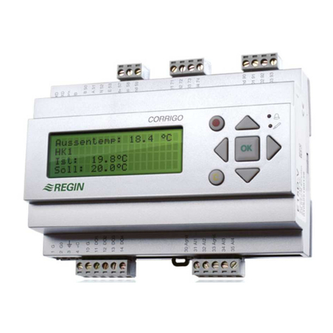
Regin CORRIGO L10 User manual

3071-A JAN 01
CORRIGO L10
!
IMPORTANT: Read these
instructions before installation
and wiring of the product.
Tel +46 (0)31 720 02 00 Fax +46 (0)31 720 02 50
Box116
42822 KÅLLERED SWEDEN
www.regin.se
INSTRUCTION 1
INSTRUCTION
Mount the controller on a DIN-rail in a panel or in a
seperate casing.
If installed in a panel front, use assembly kit FMC.
Protection class IP20
Ambient temperature 0...50ºC
Installation
Wiring
Supply voltage - Terminal 24...26
Terminals for supply 24V AC, system neutral och
protective earth.
Analogue inputs AI1...AI4 - Plint 15...19
Use Pt1000 type sensors. The usage for each sensor
is determined by the selected controller options. Use
the table on the left (Fig. 1) for quick reference to
determine sensor usage. Connect selected sensors
according to the list.
N.B. All AI inputs must refer to the common terminal for
these inputs (terminal 19). This terminal may not be
connected to any other terminals in the system.
AI1 is used, depending on configuration, either for:
1. Outdoor temperature.
2. External setpoint - input for setpoint signal.
These function are mutually exclusive. Only one of them
can be selected at a time.
CORRIGO L10 is a less complex digital controller
compared to the C10 model. This controller is
intended for use with air-handling systems and has a
simple easy-to-learn user interface. It also comes
with many system options to ensure flexibility.
CORRIGO L10 controls temperature in up to three
sequences which are configurables as either heat,
cool, damper, plate heat-exchanger or rotating heat-
exchanger. Different types of controlling functions can
be selected including supply air control with or without
compensation or zone/room control with or without
cascade function. In addition to the basic control
features it has a number of abilities such as DX-
cooling in one or two stages, controlling and monitoring
fans and pumps, alarm handling, etc.
CORRIGO L10 has a real-time clock with battery backup,
weekly timing period and automatic setting/resetting of
daylight saving time periods.
L10 is also available with a LON communication option
(model L10-LON).
Sensors...
AI2 is used for zone/room temperature in some control-
ler configurations.
AI3 is used for supply air temperature in some control-
ler configurations.
AI4 is used, depending on configuration, either for:
1. Frost protection in systems with water heater. If
shutdown mode is selected, L10 uses this input as
control value when the fans are stopped.
2. Overheat protection in systems with electric heater. In
this case it should be connected to a potential free
closing switch.
Digital inputs DI1...DI4 - Plint 3..7
The digital inputs are activated by closing switch
against terminal 7 (DI+).
N.B. This terminal must not be wired together with other
signal and/or system neutrals in the system but only as
reference point to DI1...DI4.
Reference voltage 24VAC.
DI1 Pressure switch / fan run indicator or
Fan overload protector.
DI2 Pump run indicator
DI3 Extended run (timer/pushbutton/presence) or
smoke alarm or external alarm.
DI4 Alarm for: chiller, heat exchanger, smoke detector
or external alarm.
Analogue outputs
0...10V DC outputs AO1...AO3 - Terminal 20...23
Signal 0...10V DC, 5mA.
AO1 Control output Y1
AO2 Control output Y2
AO3 Control output Y3
These outputs must refer to terminal 23, which is
signal neutral. N.B. In CORRIGO L10 this terminal is
internally connected to system neutral.
The functions of the outputs depend on the current
control configuration but the sequence order is always
Y3 ðY2 ðY1 on increasing heat demand.
Fig 1

3071-A JAN 01
CORRIGO L10 INSTRUCTION 2
INSTRUCTION
Other control outputs
Digital outputs DO1...DO5 - Terminal 8...14
These outputs are divided into two types:
DO1 and DO2 are of triac type and can handle 24V AC /
0.5A (1A short pulse load).
DO3, DO4 and DO5 are potential free relay outputs and
can handle 230V AC / 5A.
DO1 DX cooling stage 1
DO2 DX cooling stage 2 or frost protection interlock
DO3 Fan control
DO4 Pump control or electric heating interlock.
DO5 Alarm output
Language selection
CORRIGO L10 has the ability to show display in different
languages. To select another language, simply press
and hold down the !key while applying power to the
unit, it now enters language selection mode. Release
the button. To change, press the ! button once
again. The display now shows current selected
language. Press éor êbuttons until desired
language appears. Then press OK to confirm and
store your selection. Press OK once again to leave the
language selection mode and revert to the normal
menu system.
All the information which can be shown on the display
are organised as menu frames in a ’tree’-shaped
layout. This tree can be navigated up/down and left/right
using the keypad on the front. You can look at control
parameters, change parameter values and handle
alarms.
Authorization levels when logging in controls the
amount of access given to a user when accessing
parameters.
The ”trunk” of the menusystem consists of the following
menu frame items:
Login
Configuration Only shown in level 3
Inputs
Outputs
Scheduler
Settings Only shown in level 2 and 3
During normal operation when keys are not used a
series of information frames are scrolled in the display.
The first one consists of a frame showing product
identity, current time and running mode. The second
one shows setpoint/actual value for the controller and
the third shows the output levels for Y1, Y2 and Y3.
To enter the menutree press the OK key. The menu
frame will change to display Inputs.
Use the éand êkeys to move up and down the
menutree trunk. Arrows in the right margin show
whether there are more frames to be displayed above
or below current menu frame. To enter one of the
”branches” press OK. When on a branch you can use
the arrow keys in a similar manner as the trunk to see
choices or subframes. Use the Esc key to jump back
in towards the trunk.
When in a menu frame with adjustable parameter(s)
you can enter ”edit mode” by pressing the !key.
Edit mode is confirmed by a flashing cursor in the first
editable field. Use the arrow keys to change the value.
Then press the OK key to confirm and store the
changed value and the cursor will jump to the next
editable field. Repeat this procedure for the next field.
After pressing OK at the last editable field the menu-
system will leave the edit mode and resume browse
mode.
To discard a change without saving it press Esc. The
cursor jumps back to the previous field. The edit mode
is automatically abandoned after a minute of inactivity.
The key opens access to the alarm queue. It
shows active and unconfirmed alarms in the display.
The LED indicator for alarm out lights when there is at
least one alarm in the queue. It is located above the
key. If there are more than one alarm pending, use the
éê keys to browse them. Confirm with the OK key. To
abandon without any action, press the Esc key.
Setpoint/Actual
20.0°/20.0°
*CORRIGO L10-1*
O 12:09 AUT/ON Y1 / Y2 / Y3
0%/ 45%/ 0%
%
%
Login
CORRIGO L10 has 4 different user levels to prevent
changes being made to important settings by mistake.
0Not logged in. Allows user to see the most important
values and manage alarms but not to make any
changes.
1Main setpoint value, date and time can be set.
Outputs can be overridden by manual setting and
main operating mode can also be set manually to on
or off.
2Gives user access to other setpoint values and run
time settings.
3Access granted to all settable parameters. Used by
system manager when configuring the system. User
can also alter system login codes at this level.
Login procedure: If the scrolling information display is
showing press the OK key at which the display shows
Inputs.
Press the ékey until the menu frame arrow points to
Login.
Select this branch by pressing the OK key.
Login menu is now shown.
To log in, press the !key and a cursor appears at the
first code digit. Press the éê keys to increase or
decrease the value.
Press the OK key to confirm and advance to next code
digit.
If you enter the wrong value by mistake, simply press
the Esc key to revert to previous entry.
After pressing the OK key at the last code digit the login
passcode is evaluated.
Invalid passcode will render an error message. Correct
passcode results in a message stating the user level
entered.
The menusystem reverts to main menu after ca: 2 sec.
Factory settings
Corrigo L10 is delivered with following default
usercodes:
Level 1 1111
Level 2 2222
Level 3 3333
Login at level 3 to be able to change these codes.
>Inputs
á
Outputs
â
Control funct.
á
0 Suppl. air cn
â
3071-A JAN 01
CORRIGO L10 INSTRUCTION 3INSTRUCTION
Go to the login menu.
Press the êkey until the level code you wish to
change appears.
Enter the ”edit mode” by pressing the !key. A blinking
cursor appears at the first code digit.
Press the éê keys to change digit value up or down.
Press the OK key to store and confirm current digit and
advance to next code digit.
If you make a mistake you can revert to previous field by
pressing the Esc key.
When you press the OK key at the last code digit you
will see a confirmation on the newly entered login
passcode.
Store the login passcodes in a safe place. Especially
the level 3 passcode. If you lose the level 3 passcode, a
time limited emergency passcode can be obtained
from Regin AB.
Changing login passcodes
Configuration
Configuration is the process of setting all runtime
parameters in the Corrigo L10 at installation time.
The configuration menu entries are only accessible at
user level 3.
Select and enter the configuration menu.
Display shows:
Normal method (Quick method is described later in
the configuration section).
The configuration part encompasses a number of
menu frames (A...N). Advance through the menu frames
in the order you encounter them. For every menu entry,
choose the relevant setting for the application at hand.
The menu entries are briefly described here with the
available options.
For a more in-depth description please refer to the
technical manual for CORRIGO L10.
A. Control function
0Supply air control
1Supply air control with compensation
2Room/zone control with supply air temperature
cascading function.
3Room/zone control with supply air temperature
min/max limiting.
4Room/zone control without supply air temperature
sensing.
5Supply air control with compensation/Room
control with outdoor temperature dependant
changeover.
B. Output sequence Y1, Y2, Y3 (AO1, AO2, AO3)
0Heat / - / - (Y2,Y3 notactive)
1Heat / Cool / - (Y3 not active)
2Heat / Damper / - (Y3 not active)
3Heat / Damper / Cool
4Heat / Plate Exchg. / - (Y3 not active)
5Heat / Plate Exchg. / Cool
6Heat / Rot. Exchg. / - (Y3 not active)
7Heat / Rot. Exchg. / Cool
8Cool / - / - (Y2,Y3not active)
D. Frost protection
0Not activated
1Y1 Y1 Forced when frost hazard pending
2Y1 Aut.Reset Y1 Forced, automatic reset
E. Shutdown mode
Only applicable when heater is water type.
0No
1Yes
Shutdown mode means that if the system is shut down
for any reason Corrigo L10 will control the water valve
actuator to obtain a preset temperature at the frost
protection sensor. This is activated only if the pump
output DO4 is active.
This function requires a frost protection sensor at AI4.
C. Heater type
0Water heater (AI4 Frost protection)
1Electric heater (AI4 Overheat protection)
F. Pump stop
Only applicable when heater is water type.
0No
1Yes
The pump is stopped with a 15 min shut-off delay when
no heat demand is pending and outdoor temperature
exceeds a preset value. When in the stopped state an
anti-clog function runs the pump for 5 minutes every
day at 12:00.
Requires an outdoor sensor at AI1.
G. Function select - AI1
0Outdoor sensor
1External setpoint
Normally AI1 is used as input for outdoor temperature
sensor. If external setpoint is desired, change setting
and connect a setpoint adjust unit to AI1.
When set to external setpoint, no other functions
requiring outdoor temperature sensing can be used.
H. Function select - DI1
0. Fan alarm
1. Fan status indicator
Fan alarm: Connect DI1 to one or several alarm
contacts i.e. fan overcurrent protector or temperature
limit switch. On closure of the contact CORRIGO will
trigger an alarm and the unit will be shut down. Settable
alarm delay.
Fan status indicator: Connect DI1 to one ore more
pressure switches or run-indicator contacts. The
contact must be closed in order for the system to run
and the analogue outputs to be activated. If the DI1
signal is deactivated while DO3 is active the Corrigo
will activate an alarm and stop the system. Alarm delay
is fixed at 30 seconds
I. Function select - DI3
Input for use with various functions.
0. Input is not used
1. Timer for extended runtime. Presence detectors can
also be used with this setting. The system runs as
long as the input is activated.
2. Pushbutton. System runs preset extended time
after the input has been pulsed.
3. Smoke alarm. Fans are stopped on alarm.
4. External alarm. Shown as ”Extern. alarm” in alarm
queue.
Control funct.
á
0 Suppl. air cn
â

3071-A JAN 01
CORRIGO L10 INSTRUCTION 4
INSTRUCTION
J. Function select - DI4
0. Input is not used
1. Heat exchanger / Frost protection, plate exchanger
2. Alarm rotating Exchg.
3. Alarm cooling unit
4. Alarm from smoke detector. Fans are stopped
on alarm.
5. External alarm. Shown as ”Extern. alarm” in alarm
queue.
The input can be used for variuos functions. To be able
to use the plate exchanger defrosting function, the
mode selector must be set to 1 (Heat exchanger frost
detection).
K. Function select - DO1, DO2
0. -- / --
1. DX1 / --
2. -- / Frost interlock
3. DX1 / Frost interlock
4. DX1 / DX2
5. DX Binary stepping
When DX cooling is selected, at least one of the
outputs must be configured as cooling control output.
When an external fan control circuit breaker is used in
systems with frost protection, it is recommended that
this breaker is routed via this interlock output. This is to
prevent forced (manual) fan run when frost alarm is
pending.
Config.code
0501.0000.010
â
L. Factory settings
Use this option to return CORRIGO L10 to factory settings.
Press the !key, choose ”Yes” and confirm choice
with the OK key.
If you enter the !-mode and change your mind, you
can leave the edit mode by pressing the Esc key and
nothing will be changed.
User login level will be reset to 0.
All of the configuration settings and values will be reset
to its default value if this command is executed. Use
with caution. Only authorized personnel may use this
command.
The top entry in the configuration menu branch is a
shortform of the entire configuration, the config.code.
The numbers on the botton line correspond from left to
right to the menu entries A...K discussed here
previously.
Configuration, quick method
Menu entry ’L’ is not included in the configuration code.
All the configuration settings can be edited directly in
this this menu frame.
Code matrix
Using the code matrix appended it is easy to determine
the code for each control application. We recommend
that you fill this form out and save it for later reference in
the user manual.
Other menu branches
Inputs
Shows momentary values for AI1...AI4 and DI1...DI4.
Analogue inputs can be trimmed ±2K to compensate
losses. This requires user level 3.
A filter factor can be applied toAI1...AI4 if the values
appear unstable. Refer to menu branch ”Settings”.
You can also inspect min and max values for AI1...AI4
since last value reset. Refer to menu branch ”Settings”.
Outputs
Shows momentary values for AO1...AO3 and
DO1...DO5. Outputs can be forced. This requires user
level 1. If output is not set back to AUTO-mode within 15
seconds, an ”Output forced” alarm is asserted.
Scheduler
Corrigo L10 has a scheduler based on a one-week
period. This means that the days of the week can be
individually selected or deselected i the period. The
scheduler can handle power losses for at least 24
hours without loss of data.
1.Set time.
Sets weekday, date and time. Requires user level 1.
2.Period 1, 2, 3
Setting of the weekly program. Requires user level 2.
Corrigo L10 has 3 period settings for the weekly
program.
Settings
Only shown at user levels 2 or 3. This is where the
runtime parameters are set. The parameters shown
depends on the configuration
1. Running mode (Auto/Manual/Off)
2. Setpoint/Actual temperature
3. Calculated setpoint/Actual temperature
4. Setpoint supply air
5. Setpoint supply air/Compensation
6. Setpoint room/Outdoor temp for change-over
7. Min/Max limiting for supply air
8. P-Band (Y1) / I-time / Neutral zone
9. P-Band Y2 & Y3. As factor to P-Band(Y1)
10.Cascade factor and I-time
11. Room P-band/I-time
12.Compensation - Breakpoint 1
13.Compensation - Breakpoint 2
14.Compensation - Breakpoint 3
15.Compensation - Breakpoint 4
Settings 12...15:
Used in cases when outdoor temp. compensation
is selected.
The breakpoins should be placed so that BP1 is at
the lowest outdoor temperature and BP4 is at the
highest.
When temperature goes lower than BP1 or higher
than BP4 compensation amount is constant and set
to the amount for the breakpoint just passed. See
figure in next page.
For each period, choose the weekdays and time for
which the system should operate normally. Use the
arrow keys to select/deselect weekdays.
Confirm each day with the OK key.
3. Automatic DST adjustment
0. No
1. Yes
Automatic change to DST at 02:00 the last Sunday
in March.
Back to normal time at 03:00 the last Sunday in
October.

3071-A JAN 01
CORRIGO L10 INSTRUCTION 5
INSTRUCTION
Terminal connections overview
Technical support
Consult your local Regin dealer.
EMC emissions and immunity standard
This product meets or exceeds requirements for
european EMC standards CENELEC EN50081-1 and
EN50082-1 and carries the CE mark.
LVD
This product conforms with the LVD directives IEC730-1
and IEC730-2-9.
Fig. 2
Lightemitting diode (LED)
Corrigo L10 has an LED to indicate one or more
alarms in the alarm queue. When not lit it means there
are no alarms in the alarm queue. If it flashes, new
unconfirmed alarms are pending. If it is constantly lit it
means that there are confirmed but non-reset alarms in
the queue.
16.Setpoint frost protection
17.Setpoint shutdown mode
18.Pump stop temperature and delay
19. Extended run time with pushbutton on DI3
20.Cool-down time (when using electric heater)
21.DX minimum On/Off times
22.Lowered min limit on DX-cooling
23.Outdoor temp. for blocking DX-cooling
24.Show min/max for analogue inputs (Yes/no)
25.DampingofAI1...AI4
26.Parameters for deviation alarm (max diff. and delay).
27.Outdoor temperature span
28.Alarm delay - fans
29.Alarm output blocking
The alarm output can be blocked so that some
pending alarms only activate the alarm output
during certain times. In the blocked state all alarms
are blocked except frost alarm, over-temperature
alarm and smoke alarm that will always trigger the
alarm output. Although an alarm has been blocked it
will be registered and indicated by the alarm
indicator on the front panel. Texts in the alarm
queue will appear as normal.
Settings...(continued)
Factory settings
Configuration Default setting
Config. code 0501.0000.010
A. CONTROL FUNCT. 0 Supply air control
B. OUTPUT SEQUENCE 5 Heat/Plate exchg./Cool
C. HEATERTYPE 0 Water heater
D. FROST PROTECTION 1 Y1
E. SHUTDOWNMODE 0 No
F. PUMP STOP 0 No
G. FUNCTIONAI1 0 Outdoor temperature
H. FUNCTION DI1 0 Fan alarm
I. FUNCTION DI3 0 Input not used
J. FUNCTION DI4 1 Frost detection
K. FUNCTION DO1,DO2 0 Outputs not used
Storage of parameters and settings
All settings and paramters are stored in non-volatile
memory. this means that CORRIGO L10 does not have to
be reprogrammed even when subjected to very long
periods of power loss.
The real time clock in CORRIGO L10 has a powerfail
backup that lasts for about 24 hours. If subjected to
longer periods of power loss, the clock has to be set
again but the run periods in the scheduler are not
affected. Any alarms in the alarm queue will be lost
pending power failure.
1
2
3
4
5
6
7
8
9
10
11
12
13
14
15
16
17
18
19
20
21
22
23
24
25
26
Net A (L10-LON only)
NetB(L10-LON only)
DI4 Alarms cooler/Exchg./Smoke/Ext.
DI3 Ext.runtime/Smokealarm/Ext.alarm
DI2 Pumpindicator
DI1 Fan malfuct.alarm/Fan indicator
DI+ CommonDI1..DI4
C1/2 24V AC input
DO2 DX cooler stage 2
DO1 DX cooler stage 1
DO3..5 Common relay pole
DO5 Alarm output
DO4 Controlpump
DO4 Control fans
AI1 Outdoor temp./External setpoint
AI2 Roomtemperature
AI3 Supply air temperature
AI4 Frost prot./High temperature limit
MSignal neutral
AO1 Y1 0..10V DC
AO2 Y2 0..10V DC
AO3 Y3 0..10V DC
MSignal neutral
24V AC
N System neutral
Protective earth
24VAC / 0.5A
230V AC
5A
24V AC
Supply voltage

CONFIGURATION - Corrigo L10 AB C D .EFGH. I JK
Configuration code . .
A Control function
0. Supply air control 0
1.Supply air control withoutdoor temperature compensation 1
2. Room control with cascaded supply air temperature control 2
3. Room control with min/max limiting of supply air temp. 3
4. Room control, single sensor 4
5.Supply air control/Room control.Outdoor temp dependent 5
BOutpus sequences Y1, Y2, Y3
0. Heating / - / - 0
1. Heating / Cooling / - 1
2. Heating / Dampers / - 2
3. Heating / Dampers / Cooling 3
4. Heating / Plate exchanger / - 4
5. Heating / Plate exchanger / Cooling 5
6. Heating / Rotating exchanger / - 6
7. Heating / Rotating exchanger / Cooling 7
8.Cooling 8
C Heater type
0.Water heater 0
1. Electric heater 1
D Frost protection
0. Not active 0
1.Active on Y1 1
2. Active on Y1 with automatic alarm reset 2
EShutdown mode
0. No 0
1. Yes 1
F Pump stop
0. No 0
1. Yes 1
G Function AI1
0.Outdoortemperature sensor 0
1. External setpoint device 1
H Function DI1
0.Fan alarm 0
1. Fan indication 1
I Function DI3
0.Notactive 0
1.Timer 1
2. Pushbutton 2
3.Alarm, smoke detector 3
4. External alarm 4
J Function DI4
0. Not active 0
1.Freeze-upprotectionplate-exchanger 1
2.Alarm, rotatingexchanger 2
3.Alarm, chiller 3
4.Alarm, smoke detector 4
5. External alarm 5
K Function DO1, DO2
0. -- / -- 0
1. DX1 / -- 1
2. -- / Frost interlock 2
3. DX1 / Frost interlock 3
4.DX1/ DX2 in sequence 4
5.DX1/ DX2 binary 5
Numbers in bold indicate factory settings
Other manuals for CORRIGO L10
1
Table of contents
Other Regin Controllers manuals

Regin
Regin RVAN18-24 User manual

Regin
Regin RVAN18-24A User manual

Regin
Regin TTC25X User manual

Regin
Regin RVAN10-24 User manual

Regin
Regin Regio Midi User manual

Regin
Regin RDAS7S-24C User manual

Regin
Regin RDAS20-24C User manual

Regin
Regin EXOcompact C80 User manual

Regin
Regin PULSER HC-LON User manual

Regin
Regin RCF Series User manual

Regin
Regin RVAZ4-230 User manual

Regin
Regin RVAZ2-24 User manual

Regin
Regin REGIO RC-DTO User manual

Regin
Regin TTC80F User manual

Regin
Regin REGIO ARDO User manual

Regin
Regin PULSER-ADD User manual

Regin
Regin CORRIGO L10 User manual

Regin
Regin ED-RUD User manual

Regin
Regin TTC 2000 User manual

Regin
Regin Corrigo U10 Series User manual