6.
The factory electrical connections of these devices, along
with information on the connection of detection devices (initiat-
ing zones 1 and 2), signaling devices, and supervisory outputs
to the Potter PFC4410-RC Releasing Control Panel are includ-
ed in this bulletin. The power supply, standby emergency power
supply, battery charger and rectier circuitry are all contained
within the PFC4410 panel. Batteries that provide 90 hours of
standby power are provided with the panel. For additional in-
formation and detailed wiring diagrams, please refer to Potter
Manual #5403550 (Installation, Operation and Instruction of
PFC4410-RC Releasing Control Panel).
Note: In order for the solenoid valve to maintain a warranty it must
remain sealed as it came from the factory. If there are concerns
about the valve’s internal components, immediate replacement is
recommended.
System Operation (Double Interlock)
To fully activate (discharge water from) the Reliable Model
DDX Type F PrePaK system, a re detection device must ac-
tivate and pneumatic pressure must be lost from the sprinkler
system piping (normally from the activation of one or more re
sprinklers).
When the system is properly set for service, the water sup-
ply pressure simultaneously acts on both the underside of the
deluge valve’s clapper and on the valve’s push rod by means
of the pressurized push rod chamber. The resultant pressure
force acting on the push rod, in unison with the mechanical ad-
vantage of the deluge valve lever, is more than sufcient to hold
the valve clapper in the closed position against the water supply
pressure.
Energizing the releasing solenoid valve is only one of the
events required towards opening the deluge valve. Air pres-
sure in the sprinkler system must also be reduced to a level
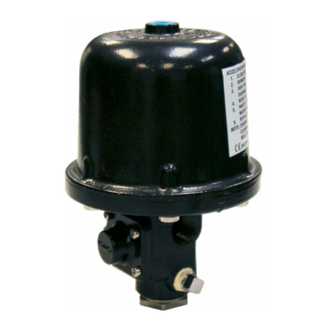
low enough to activate the Model LP Dry Pilot Actuator. Both
of these events allows the deluge valve’s push-rod chamber to
be vented to drain through its outlet. Since the push-rod cham-
ber pressure cannot be replenished through the inlet restriction
as rapidly as it is vented, the pressure falls rapidly. When the
push-rod chamber pressure drops below one-third of the wa-
ter supply pressure, the force acting beneath the valve clapper
becomes greater than the push-rod force acting on the lever
which causes the clapper to open. Refer to Reliable Technical
Bulletin 751 for further details.
Once the clapper has opened, the lever acts as a latch, pre-
venting the clapper from returning to the closed position. Water
from the supply flows through the deluge valve into the system
piping and also through the alarm outlet to activate water flow
alarm devices. Note that the solenoid valve will be maintained
open by the Potter Model PFC-4410-RC Releasing/Control
Panel latching feature until it is reset for operation.
After system shutdown and draining, the Model DDX Deluge
Valve clapper is easily reset without special tools using the ex-
ternal reset feature. Restore detection devices by resetting or
replacing any operated device. Once detection devices are re-
stored the system can be reset (see Resetting Model DDX Type
F Double Interlock Preaction System).
Resetting Model DDX Type F Double Interlock
Preaction System
1. Close the valve controlling water supply to the Deluge
Valve and close the air or nitrogen supply to the sprinkler
system.
2. Close the pushrod chamber supply valve.
3. Open main drain valve and drain system.
4. Open all drain valves and vents at low points throughout
the system, closing them when flow of water has stopped.
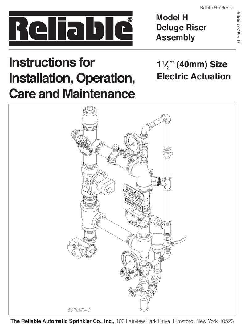
Open the Model B Manual Emergency Station to relieve
pressure in the pushrod chamber of the Deluge Valve.
5. With the alarm line valve open, push in the plunger of
ball drip valve, forcing the ball from its seat, and drain the
alarm line.
6. With the Model B Manual Emergency Station open,
push in and rotate the Deluge Valve’s external reset knob
counterclockwise (when facing the valve), until you hear a
distinct noise indicating that the clapper has reset. Note:
The reset knob can be rotated only while pressure in the
pushrod chamber is vented to atmospheric conditions (0
psig).
7. Inspect and replace any portion of the detection system
and/or sprinkler system subjected to re conditions.
8. Open the pushrod chamber supply valve and allow wa-
ter to ll the pushrod chamber. Close the Model B Manual
Emergency Station.
9. Purge all air from the actuation piping: Open the so-
lenoid valve by operating a detector or an electric manual
emergency station. Note that the Model LP Dry Pilot Actua-
tor should also be open since there is no pneumatic pres-
sure on the system.
10. While water is flowing through the solenoid valve AND
the actuator, cause the actuator to close rst by applying air
or nitrogen pressure to the system.
11. Open the air or nitrogen supply quick ll valve to restore
supervisory pressure in the sprinkler system and close the
dry pilot actuator. Allow the pressure to build to the level
specied in Table A, then set the pneumatic supply to au-
tomatic operation. (Note: To build supervisory air pressure
in the sprinkler system, it may be necessary to temporarily
close the main drain valve and the alarm line valve until air
pressure has built up to the recommended level.)
12. After the Model LP Dry Pilot Actuator has been set,
close the solenoid valve by resetting the release control
panel. (All detectors and manual pull stations must be in a
normal state before the panel can be reset.)
Note: It is important that the piping between the solenoid
valve and the dry pilot actuator is lled with water and not
air. This is accomplished by closing the dry pilot actuator
FIRST while water is flowing through the device and closing
the solenoid valve only AFTER the actuator is completely
set.
