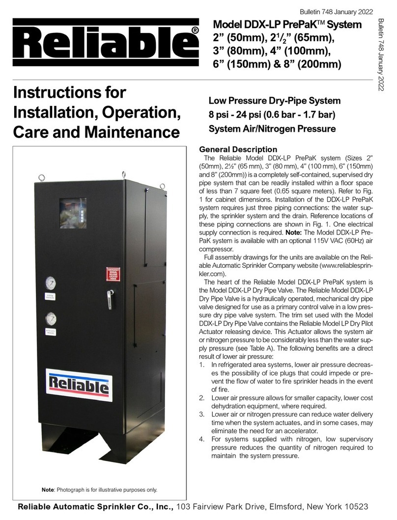
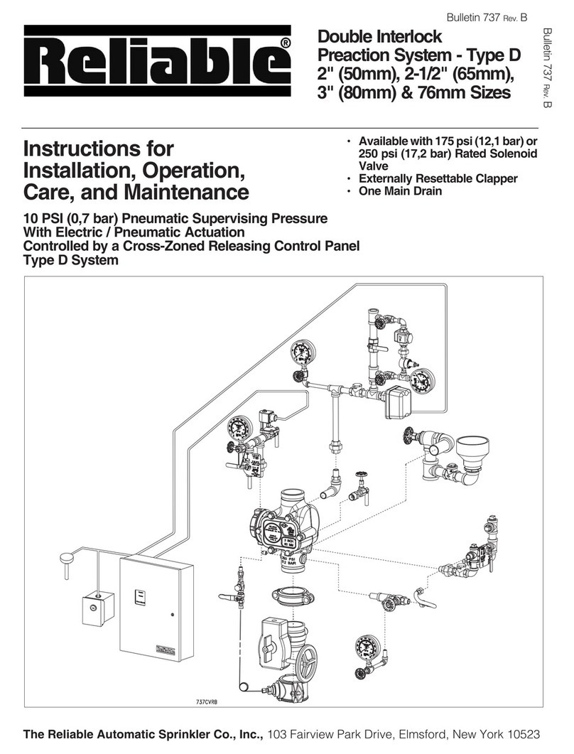
Reliable H PrePak User guide

Instructions for
Installation, Operation,
Bulletin 723 Rev.A
Model H PrePaK
Preaction System
112
²(40mm)
10 psi (0,7 bar) Pneumatic Supervising Pressure
The Reliable Automatic Sprinkler Co., Inc. , 525 North MacQuesten Parkway , Mount Vernon, New York 10552
Single Interlock
Double Interlock
Bulletin 723 Rev.A

General Description
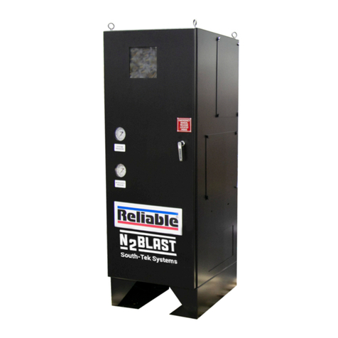
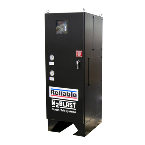
The Reliable Model H 1½²(40mm) PrePaK is a com-
pletely self-contained, supervised preaction system that
can be readily installed within a floor space of four square
feet. Installation of the PrePaK (not including exterior de-
vices, i.e., detectors and alarm bells) requires just three
piping connections: a 1½²(40mm) supply line, a 1½²
(40mm) system line, and a ¾²(20mm) drain line. Refer-
ence locations of these piping connections are shown in
Figure 1. Also, two 120 VAC electrical supply connections
are required.
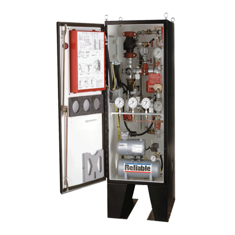
The Reliable Model H 1½²(40mm) PrePaK contains the
following components within its 64²Hx24²Wx24²D
(1625mm H x 610mm W x 610mm D) gauge 12 steel
enclosure:
•One Reliable Model H 1½²(40mm) Deluge Riser As-
sembly (See Reliable Bulletin 507).
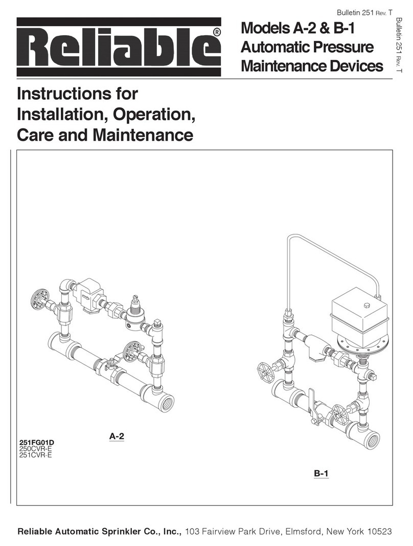
•One Reliable Model A-2 Pressure Maintenance Device
(See Reliable Bulletin 251).
•One Reliable Model G 2½²(65mm) Right-Check
Valveäw/ Preaction Trim Kit (See Reliable Bulletin
806).
•One Gast Model1 1HAB-11T-M100X 16HP Tank-Mounted
Air Compressor with 2 Gallon (7.6 liter) tank (See Reliable
Bulletin 707).
•One Potter Model PFC-4410 Fire Alarm / Releasing
Panel (See Potter Manual #5403527).
•All required fittings, gauges, electrical connectors, and
electrical devices to utilize the system in single interlock,
single interlock cross-zoned, double interlock, and dou-
ble interlock cross-zoned applications.
The Reliable Model H utilizes the Potter Model PFC-4410
Fire Alarm / Releasing Panel. This fully programmable, mi-
croprocessor based releasing panel is Underwriters Labo-
ratories, Inc. Listed and is in compliance with NFPA 13 and
NFPA 72. Because the PFC-4410 is totally zone and output
programmable, the Reliable Model H PrePaK can be uti-
lized in four different preaction applications without having
to rewire any of the factory installed devices. Once the pre-
viously described connections are completed, the 24 VDC
detectors, output devices, and relay contacts may be con-
nected to achieve the desired system implementation.
The Model H PrePaK can be used in both single and
double interlock applications. Reliable Single and Double
Interlock Preaction Systems are designed for water sensi-
tive areas, which require protection from inadvertent water
flow into the sprinkler system piping.
The major benefits of a single and/or double interlock
preaction system, when compared with a wet pipe system,
are as follows:
A. A fire alarm sounds prior to the flow of water from a sprin-
kler, which may enable extinguishing the fire by
handheld means before the operation of any sprinkler
head occurs.
B. An annunciator signals whenever the integrity of piping
or sprinklers is accidentally or intentionally disturbed;
however, no water flow or water damage will result at that
time.
C. Speedy detection and an early fire alarm are provided
by fire detectors, without the delay associated with water
delivery time in the event of a fire. Note that with a wet
pipe system, the fire alarm is delayed until after water has
begun flowing from an operated sprinkler head.
In single interlock applications, one electrical detector
senses the presence of fire, thereby causing the electrical
2.
releasing control panel to activate fire alarm devices and
latch the solenoid releasing valve in the open position.
Note that arranging detectors in a cross-zoned pattern will
require operation of two detectors before the solenoid
valve can open (Note: Cross-zoned detection systems
are not permitted in New York City and are not Factory Mu-
tual Approved). The solenoid valve, when closed, is pre-
serving supply water pressure in the inlet of the Reliable
Model H Deluge Riser Assembly. Actuating the solenoid
valve releases that water pressure, allowing water flow into
the sprinkler system in readiness for the subsequent oper-
ation of a sprinkler.
To fully operate a single interlock system with
cross-zoned detection, two separate electrical detection
systems must activate and a sprinkler must open. During
the early stages of a fire, smoke or heat activates the first
detector, which causes the control panel to produce a lo-
cal alarm and an alarm at the main fire alarm panel. Electri-
cal relays inside the releasing control panel can be used to
shut down air moving equipment or activate security
doors and other electrical devices when the panel goes
into this first alarm condition. Subsequent activation of a
second, nearby or adjacent detector, on a separate de-
tection system, will cause the panel to energize the sole-
noid valve open and release water into the sprinkler
piping. Water flowing into the sprinkler piping will simulta-
neously produce water pressure that causes the transfer
of contacts in the pressure switch mounted in the riser
assembly, thereby activating a water flow alarm device.
The flow of water into the sprinkler piping effectively con-
verts the dry system into a wet pipe system. In the event
the fire subsequently produces sufficient heat to operate a
sprinkler head, water will flow from that sprinkler, control-
ling the fire.
To flow water into a double interlock preaction system,
two events must take place. A fire detection device
must operate, and a pressure switch must be operated
by the loss of system pressure (sprinkler operation).
These two signals, both an electric signal and a pneu-
matic signal, must coexist at the releasing control panel,
which only then will energize the solenoid releasing
valve, causing water flow into the system and out of the
open sprinkler(s).
In the event that the system piping is ruptured or a
sprinkler head is accidentally opened, the system pres-
sure switch will operate and an alarm will sound. The
riser assembly, however, will not release water since the
solenoid valve remains closed due to only one input into
the control panel.
When using the Reliable Model H PrePaK in either sin-
gle or double interlock applications, the sprinkler sys-
tem is pressurized (supervised) with air provided by the
16HP tank-mounted air compressor and is monitored by
the system pressure switch.
A hydraulic manual emergency releasing station is
standard equipment in the Model H PrePaK. It is identi-
fied by a nameplate attached above the releasing valve.
Preaction trim provides a by-pass drain line and the air
supply required to supervise the preaction system at 10
psi (0,7 bar). This trim includes a UL Listed Reliable
Model G Right-CheckäValve installed with rigid
grooved pipe couplings.
Approvals
The Reliable Model H 1½²(40mm) PrePaK Preaction
System is Underwriters Laboratories Inc. (UL) Listed and
UL Certified for Canada*, as an assembled unit, in the
Figure 1 — Installation Dimensions
3.

“Special System Water Control Valves Assembled Units”
category (VKYL). New York City Approved, MEA
258-93-E, when installed in accordance with the following
guidlines and limitations:
For Single Interlock Preaction Systems:
1. Cross-zoning of preaction system detectors is prohib-
ited, except where used as a secondary system to a
gaseous suppression system.
2. A minimum of two (2) detectors must be installed for
each zone in the protected area.
3. Only Class A method of wiring detectors shall be used.
For Double-Interlock Preaction Systems:
1. Permitted only for freezer or refrigerated room applica-
tions, or where conditions will allow water to freeze in the
system piping prior to sprinkler actuation.
2. Cross-zoning of preaction system detectors is prohib-
ited, except where used as a secondary system to a
gaseous suppression system.
3. A minimum of two (2) detectors must be installed for
each zone in the protected area.
4. Only Class A method of wiring detectors shall be used.
*Electrical devices and control panel must be
specified to meet Canadian requirements. This
option is available.
Technical Data
The Reliable Model H 1½²(40mm) PrePaK is rated for a
minimum supply pressure of 20 psi (1,4 bar) and a maxi-
mum supply pressure of 175 psi (12 bar).
Friction loss, expressed in equivalent length of Sch. 40
pipe and based on Hazen-Williams formula with C=120
and a flowing velocity of 15 ft/s (4.6m/s), is 36 ft. (11m). This
friction loss value includes all components of the Model H
Riser Assembly and Model G Right-CheckäCheck Valve.
Shipping Weight: 460 lbs. (209 kg)
Enclosure Dimensions: 64²Hx24”Wx24”D
(1625mm H x 610mm W x 610mm D)
The following is a list of Technical Data Bulletins which de-
scribe the valves and devices which in this system:
Deluge Valve 507
Right-CheckäRiser Valve 806
Low Air Pressure Switch D 770-08-00 (System Sensor)
Hydraulic Emergency Station 506
Mechanical Sprinkler 612/613
Solenoid Valve 707
Water Flow Pressure Alarm D 770-08-00 (System Sensor)
Pressure Maintenance Device 707/252
Control Panel (Potter Manual #540327)
Detectors 707
Fire Alarm Devices 707
System Design Considerations
The automatic sprinklers, releasing devices, fire detec-
tion devices, manual pull stations, and signaling devices
which are utilized with the Reliable Model H 1½²(40mm)
PrePaK must be UL and/or ULC Listed, as applicable.
The steel enclosure and all interconnecting piping must
be located in a readily visible and accessible location and
in an area that can be maintained at a minimum tempera-
ture of 40°F(4°C). Note: Heat tracing is not permitted.
The solenoid valve is operated and supervised by the
Potter Electric Releasing Control Panel. Details on the elec-
trical connections of this system to a Potter Model
PFC-4410 Releasing Control Panel can by found in Potter
Manual #5403527, Installation, Operation and Instruction of
PFC-4410 Fire Alarm/Releasing Panel (this manual is in-
cluded with other pertinent manuals and shipped inside
the enclosure). This panel is fully zone and output pro-
grammable and may be adapted to several applications.
The following table provides a quick reference to various
programs (found in this Bulletin and Potter Manual
#5403527) that may be utilized with the Model H PrePaK:
(1) Refer to Potter Manual #5403527, included with the
PrePaK, for other programming options.
(2) Factory Program Setting.
System Supervising Pressure Requirements
In accordance with NFPA 13 (1996), when using the Reli-
able Model H 1½²(40mm) PrePaK in double interlock ap-
plications, a minimum of 7 psi (0,5 bar) pneumatic pressure
is required to supervise the sprinkler system. When initially
filling the system with air, the enclosure door should remain
open to provide maximum air flow to the compressor. The
Model A-2 Pressure Maintenance Device, supplied with
the system, is factory set to maintain system pneumatic
pressure at approximately 10 psi (0,7 bar).
Readjusting system pressure to approximately 10 psi
(0,7 bar) is accomplished by referring to Reliable Bulletin
251 for adjustment procedure. The low pneumatic pres-
sure supervisory switch is factory set to operate between 8
and 4 psi (0,6 bar to 0,3 bar) with decreasing pressure. Ad-
justment, if required, should be made according to Bulletin
D770-08-00 included with the switch.
System Electrical Requirements
All releasing, alarm, and detection devices in the Reliable
Model H 1½²(40mm) PrePaK are supervised by a Potter
Model PFC-4410 Releasing Control Panel. To utilize the
door of the steel enclosure as a mount for the releasing
control panel, all of the terminals are translated to two wa-
ter-tight terminal boxes mounted on the interior wall of the
enclosure. Note: The EOL resistors have also been relo-
cated. It is from these terminal boxes that all field wiring is
connected. One terminal box contains all of the 24 VDC
connections and one contains the 120 VAC connections.
The diagrams illustrating this translation of terminals are
shown in Figures 2 and 3. The Reliable Model H PrePaK is
delivered with five factory-installed electrical devices. They
consist of the following:
1. A low air, supervisory pressure switch, which is used to
monitor sprinkler piping.
2. A waterflow indicating pressure switch.
3. A releasing solenoid valve.
4. A 16HP tank-mounted air compressor.
5. A supervised, slow-close control valve.
4.
Desired
Application(1) Description Program No.
Single Interlock
Single Hazard, 2 Alarm Zones
with 1 Waterflow Zone and 2
Supervisory Zones
Potter Program #6
Custom Program
#3 (NYC)
Single Interlock,
Cross-Zoned
Single Hazard, Cross-Zoned, 2
Alarm Zones with 1 Waterflow
Zone and 2 Supervisory Zones
Potter Program
#7 (2)
Double Interlock,
2 Independent
Events
Single Hazard, 2 Alarm Zones
with 1 Waterflow Zone and 1
Supervisory Zone
Custom Program
#1
Double Interlock,
Cross-Zoned
3 Independent
Events
Single Hazard, Cross-Zoned, 3
Alarm Zones with 1 Waterflow
and 1 Supervisory Zone
Custom Program
#2

5.
Figure2—Wiring Diagram

6.
Figure3—Wiring Diagram

7.
The factory electrical connections for these devices are
illustrated in Figure 4. For information on how to install fire
detection devices to Initiating Zones 1 and 2, refer to Fig-
ures 5 or 6. For information on how to install output de-
vices, i.e., alarm bells or trouble annunciators, refer to
Figure 7. The power supply, standby emergency power
supply, battery charger and rectifier circuitry are all con-
tained within the PFC-4410 Panel. Batteries that provide
90 hours of standby power are provided with the panel.
For additional information and detailed wiring diagrams,
refer to Potter Manual #5403527, Installation, Operation
and Instruction of PFC-4410 Fire Alarm/Releasing Panel.
System Operation (Single Interlock)
To activate the Reliable Model H 1½²(40mm) PrePaK in
a single interlock application, an electrical detector (two
detectors with cross-zoned detection) must activate to fill
the system with waters. Subsequently, a sprinkler head
must open to discharge water on the fire. When a fire is
detected, the releasing control panel energizes the sole-
noid valve open and water flows from the supply through
the PrePaK to the system and to the waterflow indicating
pressure switch. The valve maintains its open position un-
til the solenoid is de-energized.
CAUTION: THE SOLENOID VALVE MUST BE
MAINTAINED OPEN TO PREVENT AUTOMATIC
CLOSING OF THE MODEL H DELUGE RISER AS-
SEMBLY. THE POTTER MODEL PFC-4410 RE-
LEASING CONTROL PANEL HAS A LATCHING
FEATURE FOR THIS PURPOSE.
After system shutdown and draining, the Model H Riser
Assembly is easily reset without special tools. Restore de-
tection devices by resetting or replacing any operated de-
vice. Once detection devices are restored, reset the
releasing control panel (Potter Manual #5403527) and the
supply pressure (see Bulletin 507, System Operation).
System Operation (Double Interlock)
To activate the Reliable Model H 1½²(40mm) PrePaK in
a double interlock application, two independent events
must coexist before water flow will occur. A fire detection
device must operate and the system pressure switch
must actuate by reducing the system supervising air pres-
sure (as a result of sprinkler operation). Operation of either
one of these items will only cause an alarm to annunciate,
and will not fill the sprinkler system piping with water. With
coexisting initiating signals, one electric and one pneu-
matic, the control panel will now energize the solenoid
valve to release water through the PrePaK into the system
piping and out the open sprinkler for complete operation
of the system.
When the releasing control panel energizes the solenoid
valve open, water flows from the supply through the riser
into the system and to the waterflow indicating pressure
switch. The valve maintains its open position until the sole-
noid is de-energized.
CAUTION: THE SOLENOID VALVE MUST BE
MAINTAINED OPEN TO PREVENT AUTOMATIC
CLOSING OF THE MODEL H DELUGE RISER AS-
SEMBLY. THE POTTER MODEL PFC-4410 RE-
LEASING CONTROL PANEL HAS A LATCHING
FEATURE FOR THIS PURPOSE.
After system shutdown and draining, the Model H
Riser Assembly is easily reset without special tools.
Restore detection devices by resetting or replacing
any operated device. Once detection devices are re-
stored, reset the releasing control panel (Potter
Manual #5403527) and the supply pressure (see Bulle-
tin 507, System Operation).
Maintenance
The Reliable Model H 1½²(40mm) PrePaK and asso-
ciated equipment shall periodically be given a thor-
ough inspection and test. NFPA 25, Inspection,
Testing and Maintenance of Water Based Fire Protec-
tion Systems, provides minimum maintenance require-
ments. Systems should be tested, operated, cleaned
and inspected at least annually, and parts replaced as
required. Periodically, open the bleeder valve on the
compressor tank to drain any condensate accumula-
tion. Refer to Bulletin 507 for information regarding
maintenance of the solenoid valve and the manual
emergency station valve. Bulletin 251 provides infor-
mation on the Model A-2 Pressure Maintenance De-
vice. Bulletin 806 describes the Model G
Right-Check™ Valve. Potter Manual #5403527 de-
scribes the PFC-4410 Fire Alarm / Releasing Panel.
Resetting Single Interlock Systems
Refer to Figure 1.
1. Close the supervised valve controlling water supply to
the Model H Riser Assembly and shut off the system air
supply at the Model A-2 Device.
2. Open all drain valves and the manual emergency station
valve to drain the system through the riser assembly.
3. Open any low point drain valves and vents throughout
the system, closing all drain valves and vents when
draining of water has stopped.
4. Inspect and replace any portion of the sprinkler system
and detection system exposed to fire conditions. Reset
detectors and PFC-4410 Releasing Control Panel. The
PFC-4410 is reset by pushing the “System Reset” but-
ton. This action will also close (reset) the solenoid valve.
5. Reset the Model H Riser Assembly in accordance with
Bulletin 507, Model H Deluge Riser Assembly Instruc-
tions for Installation, Operation, Care and Maintenance.
6. Restore the system supervising pressure to approxi-
mately 10 psi (0,7 bar) by opening the valves on the
Model A-2 Pressure Maintenance Device (refer to Bulle-
tin 251) and adjusting the regulator, as required.
7. Verify that the supervised control valve is open, and
proper monitoring has been restored. Also verify there is
no leakage from the automatic drain valve, thereby con-
firming that supply water is not leaking into the system.
Resetting Double Interlock Systems
Refer to Figure 1.
1. Close the supervised valve controlling water supply to
the Model H Riser Assembly and shut off the system’s air
supply at the Model A-2 Device.
2. Open all drain valves and the manual emergency station
valve to drain the system.
3. Open all the drain valves and vents at low points
throughout the system, closing them when flow of water
to drain has stopped.
4. Inspect and replace any portion of the sprinkler system
and detection system exposed to fire conditions. Reset
detectors. Note: It is not possible to reset the PFC-4410
panel until Step “6”, which resets the system pressure
switch, has been completed.

8.
5. Restore the system supervising pressure to approxi-
mately 10 psi (0,7 bar) by opening valves on the Model
A-2 Pressure Maintenance Device (refer to Bulletin 251)
and adjusting the regulator, as required.
6. Verify that the bypass drain valve is closed to prevent
the loss of pneumatic supervising pressure out of the
automatic drain valve. When the supervising pressure
has reached the 10 psi (0,7 bar) setting, the low air
pressure switch will automatically reset (contacts now
open).
7. With the low air pressure switch reset (Step “6”) and all
detectors replaced or reset (Step “4”), the PFC-4410
Releasing Control Panel can be reset. Pushing the
“System Reset” button on the panel will simultaneously
restore the solenoid valve to the closed condition.
8. Restore water supply to the Model H Riser Assembly in
accordance with Bulletin 507, Model H Deluge Riser
Assembly Instructions for Installation, Operation, Care,
and Maintenance.
Inspection and Testing of Single Interlock
Refer to Figure 1.
1. Water supply - be sure the supervised valve controlling
water supply to the Model H Riser Assembly is open
fully and properly supervised.
2. Other trimming valves - check that all pressure gauge
valves are open, and that the Model A-2 Pressure Main-
tenance Device ¾²NPT fill valve is closed. The two ¼²
NPT bypass line valves must be fully open.
3. Check that system supervising pressure is approxi-
mately 10 psi (0,7 bar).
4. Operation test - for detection only, operate by actuation
of a keyed manual (electrical) emergency station (refer
to Figure 5 for wiring instructions). Double interlock sys-
tems also require the supervisory pressure to be dis-
charged, through the inspectors test station or other
venting means, below 4 psi (0,3 bar) before total system
operation will occur.
Note: Total system operation testing will cause water
flow through the Model H Riser Assembly and into the
system. Where difficulty in performance is experi-
enced, contact Reliable Technical Services before any
field adjustment is to be made.
Testing Detection System Without
Causing Water Flow (Single Interlock)
Refer to Figure 1.
1. Close the supervised valve controlling water supply to
the Model H Riser Assembly, and note the water pres-
sure gauge reading. Also, shut off the system air at the
Model A-2 Device.
2. Operate the detection system - operate a cross-zoned
releasing control panel by operating two detectors.
3. Operation of the detection system must result in a
sudden drop of water pressure as the solenoid valve
opens. When the water pressure gauge drops to
zero, open main drain valve, bypass drain valve and
manual emergency station valve until all water above
the supervised control valve drains away.
4. Reset detection system - reverse operations performed
in Step “2” above. All detection devices must be reset
before the PFC-4410 Releasing Control Panel can be
reset. The solenoid valve closes when the releasing
panel is reset. Close the bypass drain valve and manual
emergency station valve.
5. Slightly open the supervised valve controlling water
supply to the Model H Riser Assembly, closing main
drain valve when water flows steadily. Open slowly, but
fully, the supervised control valve and monitor it prop-
erly.
6. It is necessary to shut down the supervisory pressure
supply (ref. Step “1”) during testing; otherwise, low
pressure annunciation can occur when the drain valves
are opened in Step “3”. Restore the supervisory pres-
sure to 10 psi (0,7 bar) at this time.
Testing Detection System Without
Causing Water Flow (Double Interlock)
Refer to Figure 1.
1. Close the supervised valve controlling water supply to
the Model H Riser Assembly, and note the lower water
pressure gauge reading.
2. Operate a double interlock system by operating one
detector and also venting the supervising pressure,
through the inspectors test station, below 4 psi (0,3 bar),
to operate the low air pressure switch.
3. Operation of a detector and the system pressure switch
must result in a sudden drop of water pressure as the
solenoid valve opens. When the water pressure gauge
drops to zero, open the main drain and bypass drain
valves until all water above the supervised control valve
drains away.
4. Reset system by following the operation described pre-
viously in Steps “5” through “7” of the section named
“Resetting Double Interlock Systems.” All detection
devices must be reset before the PFC-4410 Releasing
Control Panel can be reset.
5. Open slightly the supervised valve controlling water
supply to the Model H Riser Assembly, closing the main
drain valve after water flows steadily through it. Open
slowly, but fully, the control valve and supervise it prop-
erly. Verify there is adequate water supply pressure
and proper pneumatic supervisory pressure on the ap-
propriate gauges. There should be no pressure read-
ing on the water gauge directly above the manual
emergency releasing station when the system is prop-
erly reset.

Figure4—Wiring Diagram
9.

Figure5—Wiring Diagram
10.

Figure6—Wiring Diagram
11.

Figure7—Wiring Diagram
12.

6. Press the SELECT (middle) button until the display
reads “PROGRAM #6.”
7. Press the SET (top) button.
8. The panel is completely programmed except for the
custom banner and zone messages. Slide the pro-
gram switch back to the left.
POTTER PROGRAM #6
ZONES
#1 #2 #3 #4
OUTPUTS Supervisory Conventional Manual Release Waterflow Low Air
#1 ALARM X X
#2 ALARM X
#3 SUPERVISORY X X
#4 RELEASE X X
INPUT: 1 conventional zone, 1 manual release zone, 1 waterflow zone, 1 low air zone, 1 supervisory zone.
OUTPUT: 1 general alarm bell, 1 waterflow bell, 1 supervisory bell, 1 solenoid release circuit.
OPERATION: Activation of either the conventional zone or the manual release will operate the solenoid
release circuit and the general alarm bell.
Activation of the waterflow zone will operate the waterflow bell.
Activation of either the low air zone or the supervisory zone will operate the supervisory bell.
When either Zone #1 or #2 is in alarm, Output #1 (general alarm) and Output #4 (solenoid release)
will operate.
When Zone #3 is in alarm, Output #2 (waterflow bell) will operate.
When either Zone #4 or the supervisory zone is activated, Output #3 (supervisory bell) will operate.
Potter Program #6
Single Interlock Programming Instructions (Single
Hazard, 2 Alarm Zones, 1 Waterflow Zone, and 2
Supervisory Zones)
1. Apply power to panel.
2. Slide the program switch to the right.
3. Press the FUNCTION (bottom) button until the display
reads “PASSWORD = 000.”
4. To enter a password, press the SELECT (middle) but-
ton until the proper number is displayed above the “^”
symbol; then press the SET (top) button to move to the
next digit. After entering the third number the display
will change. (All panels are shipped with a “000” pass-
word).
5. Press the FUNCTION (bottom) button until the display
reads “PROGRAM ##” (the second “#” character refers
to the current program number).
13.

14.
Figure 8 - Wiring Diagram

Press the FUNCTION (bottom) button until the display
reads “PROGRAM ##” (the second “#” character refers
to the current program number).
Press the SELECT (middle) button until the display
reads “PROGRAM #7.”
Press the SET (top) button.
The panel is completely programmed except for the
custom banner and some zone messages. Slide the
program switch back to the left.
Potter Program #7
Single Interlock Programing Instructions (Single
Hazard - Cross-Zoned, 2 Alarm Zones, 1 Waterflow
Zone and 2 Supervisory Zones)
Apply power to panel.
Slide the program switch to the right.
Press the FUNCTION (bottom) button until the display
reads “PASSWORD = 000.”
To enter a password, press the SELECT (middle) but-
ton until the proper number is displayed above the “^”
symbol; then press the SET (top) button to move to the
next digit. After entering the third number the display
will change. (All panels are shipped with a “000” pass-
word.)
ZONES
#1 #2 #3 #4
OUTPUTS Supervisory Conventional Conventional Waterflow Low Air
#1 ALARM X X
#2 ALARM X
#3 SUPERVISORY X X
#4 RELEASE X X
INPUT: 2 conventional zones (cross-zoned), 1 waterflow zone, 1 low air zone, 1 supervisory zone.
OUTPUT: 1 general alarm bell, 1 waterflow bell, 1 supervisory bell, 1 solenoid release circuit.
OPERATION: Activation of both conventional zones at the same time will operate the solenoid release circuit and
the general alarm bell.
Activation of either conventional zone will operate the general alarm bell.
Activation of the waterflow zone will operate the waterflow bell.
Activation of either the low air zone or the supervisory zone will operate the supervisory bell.
When either Zone #1 or #2 is in alarm, Output #1 (general alarm) will operate.
When Zones #1 and #2 are in alarm at the same time, Output #4 (solenoid release) and Output #1
(general alarm) will operate.
When Zone #3 is in alarm, Output #2 (waterflow bell) will operate.
When either Zone #4 or the supervisory zone is activated, Output #3 (supervisory bell) will operate.
1.
2.
3.
4.
POTTER PROGRAM #7
5.
6.
7.
8.
15.

16.
Figure 9 - Wiring Diagram

17.
Custom Program #1
Double Interlock Programming Instructions
(Single Hazard, 2 Alarm Zones, 1 Waterflow Zone,
and 1 Supervisory Zone)
1. Apply power to the panel.
2. Slide the program switch to the right.
3. Press the FUNCTION (bottom) button until the display
reads “PASSWORD=000.”
4. To enter a password, press the SELECT (middle) but-
ton until the proper number is displayed above the “^”
symbol; then press the SET (top) button to move to the
next digit. After entering the third number, the display
will change. (All panels are shipped with a “000”
password).
5. Press the FUNCTION (bottom) button until the display
reads “PROGRAM ##” (the second “#” character re-
fers to the current program number).
6. Press the SELECT (middle) button until the display
reads “PROGRAM #7.”
7. Press the SET (top) button.
8. Slide the program switch to the left.
9. Slide the program switch to the right.
10. Press the FUNCTION (bottom) button until the display
reads “PASSWORD=000.”
11. Enter the password.
12. Press the FUNCTION (bottom) button until the display
reads “PROGRAM #7.”
13. Press the SELECT (middle) button until the display
reads “PROGRAM #0.”
The PFC-4410 assigns a “PROGRAM #0” designation
to any custom program.
14. Press the SET (top) button until the display reads “INIT
ZONE #2 CONVENTIONAL.”
15. Press the SELECT (middle) button until the display
reads “INIT ZONE #2 LOW AIR.”
This is done to eliminate Zone #2 from the program-
ming sequence. If this were not done, it would take
three events to activate Output #4 (Solenoid Release),
instead of the two, which is desired. Therefore, Zone
#2 should be empty with no devices connected to it.
16. Press the SET (top) button until the display reads
“INIT ZONE #4 LOW AIR.”
17. Press the SELECT (middle) button until the display
reads “INIT ZONE #4 CONVENTIONAL.”
18. Press the SET (top) button.
19. Press the FUNCTION (bottom) button until the display
reads “ZONE #4 OUTPUTS.”
The “v” is pointing to the first available output for the
zone indicated on the display. If the output number is
displayed, it is turned on for that zone. If the number is
not displayed, it is turned off. Output #3 will not be
available to Zone #4 because it is a supervisory output
and Zone #4 is an alarm zone.
20. Press the SELECT (middle) button. The “1” should ap-
pear under the “v.”
21. Press the SET (top) button twice. The “v” should be on
the far right of the display.
22. Press the SELECT (middle) button. The “4” should ap-
pear under the “v.”
23. Press the SET (top) button.
24. Slide the program switch to the left.
INPUT: 2 conventional zones (cross-zoned panel), 1 waterflow zone, and 1 supervisory zone.
OUTPUT: 1 general alarm bell, 1 waterflow bell, 1 supervisory bell, and 1 solenoid release circuit.
OPERATION: Activation of both conventional zones at the same time will operate the solenoid release circuit and the
general alarm bell.
Activation of any conventional zone will operate the general alarm bell.
Activation of the waterflow zone will operate the waterflow bell.
Activation of the supervisory zone will operate the supervisory bell.
When Zones #1 and #4 are in alarm at the same time, Output #4 (solenoid) and Output #1 (general
alarm) will operate.
When either Zones #1 or #4 are in alarm, Output #1 (general alarm) will operate.
When Zone #3 is in alarm, Output #2 ( bell) will operate.
When the supervisory zone is activated, Output #3 (supervisory bell) will operate.
ZONES
OUTPUTS Supervisory
#1
Conventional
#2
Low Air
(Empty)
#3
Waterflow
#4
Conventional
#1 Alarm X X
#2 Alarm X
#3 Supervisory X X
#4 Release X X
CUSTOM PROGRAM #1

18.
Figure 10 — Wiring Diagram

Custom Program #2
Double Interlock Programming Instructions
(Single Hazard - Cross-Zoned, 3 Alarm Zones, 1
Waterflow Zone, and 1 Supervisory Zone)
1. Apply power to the panel.
2. Slide the program switch to the right.
3. Press the FUNCTION (bottom) button until the display
reads “PASSWORD=000.”
4. To enter a password, press the SELECT (middle) but-
ton until the proper number is displayed above the “^”
symbol; then press the SET (top) button to move to the
next digit. After entering the third number, the display
will change. (All panels are shipped with a “000”
password.)
5. Press the FUNCTION (bottom) button until the display
reads “PROGRAM ##” (the second “#” character re-
fers to the current program number).
6. Press the SELECT (middle) button until the display
reads “PROGRAM #7.”
7. Press the SET (top) button.
8. Slide the program switch to the left.
9. Slide the program switch to the right.
10. Press the FUNCTION (bottom) button until the display
reads “PASSWORD=000.”
11. Enter the password.
12. Press the FUNCTION (bottom) button until the dis-
play reads “PROGRAM #7.”
13. Press the SELECT (middle) button until the display
reads “PROGRAM #0.”
The PFC-4410 assigns a “PROGRAM #0” designa-
tion to any custom program.
14. Press the SET (top) button until the display reads
“ZONE #4 LOW AIR”.
15. Press the SELECT (middle) button until the display
reads “ ZONE #4 CONVENTIONAL.”
16. Press the SET (top) button.
17. Press the FUNCTION (bottom) button until the display
reads “ZONE #4 OUTPUTS.”
The “v” is pointing to the first available output for the
zone indicated on the display. If the output number is
displayed, it is turned on for that zone. If the number is
not displayed, it is turned off. Output #3 will not be
available to Zone #4 because it is a supervisory output
and Zone #4 is an alarm zone.
18. Press the SELECT (middle) button. The “1” should ap-
pear under the “v.”
19. Press the SET (top) button twice. The “v” should be on
the far right of the display.
20. Press the SELECT (middle) button. The “4” should ap-
pear under the “v.”
21. Press the SET (top) button.
22. Slide the program switch to the left.
CUSTOM PROGRAM #2
INPUTS: 3 conventional zones (cross-zoned panel), 1 waterflow zone, and 1 supervisory zone.
OUTPUTS: 1 general alarm bell, 1 waterflow bell, 1 supervisory bell, and 1 solenoid release circuit.
OPERATION: Activation of all three conventional zones at the same time will operate the solenoid release
circuit and the general alarm bell.
Activation of any conventional zone will operate the general alarm bell.
Activation of the waterflow zone will operate the waterflow bell.
Activation of the supervisory zone will operate the supervisory bell.
When Zones #1, #2, and #4 are in alarm at the same time, Output #4 (solenoid release) and
Output #1 (general alarm) will operate.
When either Zones #1, #2, or #4 are in alarm, Output #1 (general alarm) will operate.
When Zone #3 is in alarm, Output #2 (waterflow bell) will operate.
When the supervisory zone is activated, Output #3 (supervisory bell) will operate.
ZONES
OUTPUTS Supervisory
#1
Conventional
#2
Conventional
#3
Waterflow
#4
Conventional
#1 Alarm X X X
#2 Alarm X
#3 Supervisory X
#4 Release X X X
19.

Figure 11 — Wiring Diagram
20.
Other manuals for H PrePak
2
Table of contents
Other Reliable Industrial Equipment manuals

Reliable
Reliable R0029B User manual

Reliable
Reliable H Deluge Riser Maintenance manual

Reliable
Reliable A-2 Maintenance manual

Reliable
Reliable H PrePak Maintenance manual

Reliable
Reliable Double Interlock Preaction System D Maintenance manual

Reliable
Reliable NS-ASAM Manual

Reliable
Reliable 500PS User manual

Reliable
Reliable F1FR56 User manual

Reliable
Reliable DDX PrePaK User manual

Reliable
Reliable B1 Maintenance manual