Installation and Adjustment
1. Securely mount the NS-ASAM enclosure to the wall using
the keyhole slots.
2. Confirm that all valves are closed.
3. Securely mount and properly pipe the primary and sec-
ondary sources of nitrogen or air in accordance with
appropriate local, state, or federal standards.
4. Connect the primary source of nitrogen or air to the prima-
ry inlet of the NS-ASAM and connect the secondary source
of nitrogen or air to the secondary inlet of the NS-ASAM.
5. Connect the NS-ASAM outlet to the port provided for pneu
matic supply to the sprinkler system (see note 1).
6. Before applying pressure to the sprinkler system, turn the
adjustment screw on the System Pressure Regulator within
the NS-ASAM fully counterclockwise.
7. Adjust the primary and secondary sources of nitrogen or
air to a recommended pressure of 120 psi (8.3 bar); the
minimum required inlet pressure is 100 psi (6.9 bar) and
the maximum rated inlet pressure is 250 psi (7.2 bar).
8. Open the Primary Inlet Valve and the Secondary Inlet
Valve.
9. Open the Bypass Valve and the NS-ASAM Outlet Valve to
allow nitrogen or air to flow into the system piping.
10. When the system pressure rises to within 2 psi (0.15 bar)
of the required system pressure, fully close the Bypass
Valve.
11. Slowly turn the adjustment screw of the System Pressure
Regulator clockwise to increase pressure to the level
required by the system. Tighten the lock-nut on the System
Pressure Regulator (see note 2).
12. If desired, supervise the contacts of the Pressure Switch in
accordance with NFPA 72 to provide notification that the
primary nitrogen or air source is depleted. The auxiliary
contacts of the pressure switch may also be supervised to
indicate depletion of the secondary source of nitrogen or
air. When supervising the auxiliary contacts, the primary
contacts of the pressure switch should remain at the
factory setting of 90 psi (6.2 bar) to indicate depletion of
the primary source and the auxiliary contacts should be
adjusted to a pressure setting of approximately 70 psi (4.8
bar).
13. If necessary, adjust the setting of the low-pressure switch
for each system.
14. Use a soap solution at all joints to verify leak-tight connec-
tions.
Notes:
1. When applying more that one system, each system must
have an individual Pressure Maintenance Device.
2. For multiple systems, the NS-ASAM system regulator must
be set a minimum of 5 psi above the highest system pres-
sure required. Use the regulator on the Pressure
Maintenance Device of each system to make final
adjustment.
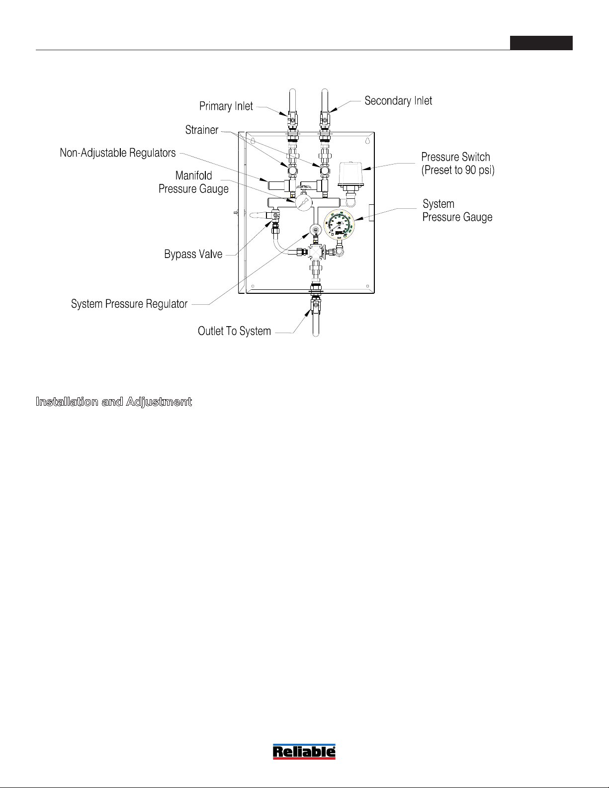
Model NS-ASAM Components Figure 2
Bulletin 254
May 2019
Page 3 of 7
www.reliablesprinkler.com