manuals.online logo
Brands
  1. Home
  2. •
  3. Brands
  4. •
  5. Reliable
  6. •
  7. Irrigation System
  8. •
  9. Reliable F3QR56 User manual

Reliable F3QR56 User manual

The Reliable Automatic Sprinkler Co., Inc., 103 Fairview Park Drive, Elmsford, New York 10523
Multilingual document:
Select your language below
Model F3QR56
Dry K5.6 (80 metric)
Quick-Response,
Standard Spray Sprinklers
Features
1. Available in the following configurations:
• Pendent with standard escutcheon
• Pendent with Model HB extended escutcheon
• Pendent with Model FP recessed escutcheon
• Pendent with Model F1 recessed escutcheon
• Concealed Pendent with Model CCP cover plate
• Horizontal Sidewall with Standard escutcheon
• Horizontal Sidewall with Model HB extended
escutcheon
• Horizontal Sidewall with Model FP
recessed escutcheon (FM Standard Response)
• Horizontal Sidewall with Model F1
recessed escutcheon (FM Standard Response)
2. Available with 1" NPT, ISO 7‑1R1, 3/4" NPT, or ISO 7‑1
R
3/4inlet fitting.
3. 3/4" NPT inlet fittings permit replacement of older 3/4"
inlet dry sprinklers without changing to a larger sprinkler
fitting.
4. Sprinklers, escutcheons, and cover plates are available
in a wide variety of standard and special application
finishes.
5. White polyester, black polyester, and Electroless
Nickel PTFE (ENT) finish sprinklers are cULus Listed as
Corrosion Resistant.
6. Available with cULus Listed 250 psi (17.2 bar) pressure
rating for Dry Pendent and select HSW configurations.
FM Approved for 175 psi (12 bar).
Product Description
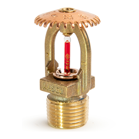
Model F3QR56 Dry sprinklers are quick‑response,
standard coverage sprinklers with a nominal K‑factor of
5.6 (80 metric). Available in Dry Pendent or Dry Horizontal
Sidewall configurations, Model F3QR56 Dry sprinklers all use
a 3 mm glass bulb operating element. See the Temperature
Ratings table in this Bulletin for available temperature ratings.
Model F3QR56 Dry sprinklers are intended for installation
on wet‑pipe, dry‑pipe, or preaction sprinkler systems in
accordance with NFPA 13, FM Property Loss Prevention
Data Sheets, and other applicable installation standards.
Model F3QR56 Dry sprinklers are available with a variety
of escutcheon options as illustrated in Figs. 1 through 3 and
Figs. 5 through 9. In addition, Model F3QR56 Dry Pendent
sprinklers are also available with the Model CCP conical
concealed cover plate as illustrated in Fig. 4. Available
sprinkler, escutcheon, and cover plate finishes are identified
in the Finishes table in this Bulletin. The Model F1 escutcheon,
Model FP escutcheon, and Model CCP cover plate are the
Concealed
(See Fig. 4)
Recessed FP Pendent
(See Fig. 3)
Recessed F1
Horizontal Sidewall
(See Fig. 9)
Horizontal Sidewall
(See Fig. 6)
Pendent
(See Fig. 1)
Recessed F1 Pendent
(See Fig. 5)
Recessed FP
Horizontal Sidewall
(See Fig. 8)
Pendent / HB
(See Fig. 2)
Horizontal Sidewall / HB
(See Fig. 7)
Bulletin 157 Rev. M_Multilingual
2
only recessed escutcheons and cover plate listed for use with
Model F3QR56 Dry sprinklers; the use of any other recessed
escutcheon or cover plate with Model F3QR56 Dry sprinklers
will void all guarantees, warranties, listings and approvals.
Inlet fittings are available with 1" NPT, ISO 7‑1R1, 3/4"
NPT, or ISO 7‑1R
3/4threads. Sprinklers with 3/4" NPT
and ISO 7‑1R
3/4inlet fittings are intended primarily for
replacement of existing 3/4" or ISO 7‑1R
3/4inlet dry
sprinklers, but may also be used in new installations.
See the Available Configurations, Listings, and Approvals
table in this Bulletin for further information on Model F3QR56
Dry sprinklers.
Available Configurations, Listings, and Approvals
Sprinkler Model Escutcheon or
Cover Plate Available Length
(See Figs. 1-9) Listings and
Approvals(1) Inlet Threads Sprinkler Identification
Number (SIN)
F3QR56 Dry Pendent
Standard Escutcheon 2"‑36" (50‑900 mm)
cULus, NYC
3/4" NPT
or
ISO 7‑1R
3/4
R5714
HB Extended Escutcheon
3
‑
1/2"‑36"
(90‑900 mm)
F1 Recessed Escutcheon
FP Recessed Escutcheon
CCP Cover Plate
Standard Escutcheon 2"‑48" (50‑1200 mm)
cULus, FM, NYC 1" NPT
or
ISO 7‑1R1
HB Extended Escutcheon
3
‑
1/2"‑48"
(90‑1200 mm)
F1 Recessed Escutcheon
FP Recessed Escutcheon
CCP Cover Plate
F3QR56 Dry
Horizontal Sidewall
Standard Escutcheon 2"‑48" (50‑1200 mm)
cULus(2), NYC(2)
3/4" NPT
or
ISO 7‑1R
3/4
R5734
HB Extended Escutcheon
3
‑
1/2"‑48"
(90‑1200 mm)
F1 Recessed Escutcheon
FP Recessed Escutcheon
Standard Escutcheon 2"‑48" (50‑1200 mm)
cULus(2), FM(3), NYC(2)
1" NPT
or
ISO 7‑1R1
HB Extended Escutcheon 3
‑
1/2"‑48"
(90‑1200 mm)
F1 Recessed Escutcheon 3
‑
1/2"‑48"
(90‑1200 mm) cULus(2), FM(3)(4), NYC(2)
FP Recessed Escutcheon
(1) For available temperature ratings and finishes see the Temperature Ratings and Finishes tables, respectively, in this Bulletin.
(2) cULus Listing and NYC for Light Hazard and Ordinary Hazard only.
(3) FM Approved for Light Hazard only.
(4) Model F3QR56 Dry Horizontal Sidewall with Model F1 or Model FP recessed escutcheon are FM Approved as Standard Response.
3
Patents
Model F3QR56 Dry series sprinklers may be covered by one or more of the following patents:
US Patent No. 5.775.431
US Patent No. 5.967.240
Listing and Approval Agencies
See the Available Configurations, Listings, and Approvals table in this Bulletin for listings and approvals applicable to each
available configuration.
1. Listed by Underwriters Laboratories, Inc. and UL Certified for Canada (cULus)
2. Certified by FM Approvals (FM)
3. Permitted in New York City based on UL Listing per Local Law 33/2007 (NYC)
Technical Data
Nominal K‑factor: 5.6 gpm/psi½(80 l/min/bar½)
Sprinkler Listing or Approval Deflector to Ceiling Distance Maximum Working Pressure
F3QR56 Dry Pendent cULus, NYC —250 psi (17.2 bar)
FM —175 psi (12 bar)
F3QR56 Dry Horizontal Sidewall cULus, NYC 4"‑6" 250 psi (17.2 bar)
6"‑12" 175 psi (12 bar)
FM —175 psi (12 bar)
Temperature
Classification Glass Bulb Color Sprinkler
Temperature Rating Cover Plate
Temperature Rating Maximum Ceiling
Temperature Listings and Approvals(1)
Ordinary Orange 135 °F (57 °C) 135 °F (57 °C) 100 °F (38 °C) cULus, FM, NYC
Red 155 °F (68 °C)
Intermediate Yellow 175 °F (79 °C) 165 °F (74 °C) 150 °F (66 °C) cULus, NYC
Intermediate Green 200 °F (93 °C) 165 °F (74 °C) 150 °F (66 °C) cULus, FM, NYC
High Blue 286 °F (141 °C) None 225 °F (107 °C) cULus, FM(2), NYC
165 °F (74 °C) 150 °F (66 °C) cULus, NYC
(1) For listed and approved sprinkler, escutcheon, and inlet configurations see the Available Configurations, Listings, and Approvals table in this Bulletin.
(2) High temperature classification is FM Approved with Standard and Model HB escutcheons only.
Finishes
Component Sprinkler Escutcheon(1) Cover Plate
Standard Finishes
Bronze Brass(3) White Paint
White Polyester(2) White Polyester Chrome
Chrome Chrome
Special Application Finishes
Electroless Nickel PTFE(2)
Electroless Nickel PTFE
Black Polyester
Customer Color Polyester
Satin Chrome
Black Paint
Custom Color Paint
Black Plating
Black Polyester(2)
Custom Color Polyester
(1) Standard and Model HB escutcheons are supplied with both the can and escutcheon finished. Model F1 escutcheons are supplied with both the collar
and escutcheon finished. Model FP escutcheons are supplied with the escutcheon finished; the cup is galvanized steel with no further finish.
(2) cULus Listed as a Corrosion Resistant Sprinkler.
(3) Brass finish available for standard, Model F1, and Model FP escutcheons only.
4
153FG01-G
Note: The sprinkler can protrudes 1/4" when escutcheon is in nominal position. Escutcheon adjustment provides −1/4" (−6 mm) to +1
‑
1/4" (+32 mm) “A”
dimension adjustment range.
Sprinkler Guard: Model C2
Fig. 1
Model F3QR56 Dry Pendent Sprinkler with Standard Escutcheon (SIN R5714)
“A” Dim. 2" to 48" (51 mm to 1219 mm) in 1/4" (6 mm) increments for 1" connections or
2" to 36" (51 mm to 914 mm) in 1/4" (6 mm) increments for 3/4" connections
SYSTEM FITTING
INLET FITTING
“A” DIMENSION
2
‑
1/8" (54 mm DIA.
HOLE IN CEILING
1
‑
21/32" DIA. (42 mm)
SPRINKLER CAN
ESCUTCHEON
NOMINAL
ESCUTCHEON
POSITION
1/4" (6 mm) PROTRUSION AT
NOMINAL ESCUTCHEON POSITION
1
‑
1/2" (38 mm)
TOTAL ADJUSTMENT
1
‑
1/4" (32 mm)
ESCUTCHEON ADJUSTMENT
1/4" (6 mm)
ESCUTCHEON ADJUSTMENT
1
‑
5/8" (41 mm)
3" (76 mm) DIA.
CEILING
CEILING
CEILING
5
157FG02B
Model F3QR56 Dry Pendent Sprinkler with Model HB Extended Escutcheon (SIN R5714)
“A” Dim. 3
‑
1/2" to 48" (89 mm to 1219 mm) in 1/4" (6 mm) increments for 1" connections or
3
‑
1/2" to 36" (89 mm to 914 mm) in 1/4" (6 mm) increments for 3/4" connections
Note: The sprinkler can protrudes 1
‑
1/4" when escutcheon is in nominal position. Escutcheon adjustment provides −1/2" (−12.7 mm) to +1/2" (+12.7 mm) “A”
dimension adjustment range.
Sprinkler Guard: Model C2
Fig. 2
SYSTEM FITTING
INLET FITTING
1/2" (12.5 mm)
ESCUTCHEON ADJUSTMENT
1" (25 mm) TOTAL
ESCUTCHEON ADJUSTMENT
1/2" (12.5 mm)
ESCUTCHEON ADJUSTMENT
NOMINAL POSITION
OF ESCUTCHEON
1
‑
5/8" (41 mm)
3
‑
1/2" (89 mm)
ESCUTCHEON DIA.
2
‑
1/2" (64 mm DIA.
HOLE IN CEILING
“A” DIMENSION
CEILING
ESCUTCHEON
1
‑
1/4" (32 mm) PROTRUSION AT
NOMINAL ESCUTCHEON POSITION
2
‑
3/16" (56 mm) DIA.
SPRINKLER CAN
6
153FG02-F
Note: Do not install the Model F3QR56 Dry Pendent sprinkler with the Model FP escutcheon in ceilings which have positive pressure in the space above.
Fig. 3
Model F3QR56 Dry Pendent Sprinkler with Model FP Recessed Escutcheon (SIN R5714)
“A” Dim. 3
‑
1/2" to 48" (89 mm to 1219 mm) in 1/4" (6 mm) increments for 1" connections or
3
‑
1/2" to 36" (89 mm to 914 mm) in 1/4" (6 mm) increments for 3/4" connections
SYSTEM FITTING
INLET FITTING
1/4" (6 mm)
ESCUTCHEON ADJUSTMENT
2
‑
1/2" (64 mm DIA.
HOLE IN CEILING
“A” DIMENSION
CEILING
ESCUTCHEON
NOMINAL
ESCUTCHEON
POSITION
3
‑
7/32" (82 mm) DIA.
SPRINKLER
CUP
CEILING
1/4" (6 mm)
ESCUTCHEON ADJUSTMENT
1/2" (12 mm) TOTAL
ESCUTCHEON ADJUSTMENT
2
‑
9/32" (58 mm) DIA.
7
153FG03-F
Model F3QR56 Dry Pendent Sprinkler with Model CCP Cover Plate (SIN R5714)
“A” Dim. 3
‑
1/2" to 48" (89 mm to 1219 mm) in 1/4" (6 mm) increments for 1" connections or
3
‑
1/2" to 36" (89 mm to 914 mm) in 1/4" (6 mm) increments for 3/4" connections
Note: Do not install the Model F3QR56 Dry Pendent sprinkler with the Model CCP cover plate in ceilings which have positive pressure in the space above.
Fig. 4
2
‑
1/2" (64 mm DIA.
HOLE IN CEILING
NOMINAL COVER
PLATE POSITION
3/16" (5 mm) COVER
PLATE ADJUSTMENT
3/16" (5 mm) COVER
PLATE ADJUSTMENT
3/8" (10 mm) TOTAL COVER
PLATE ADJUSTMENT
SYSTEM FITTING
INLET FITTING
SPRINKLER CUP
ASSEMBLY
MODEL CCP 1/2 COVER PLATE
ASSEMBLY (ADJUSTMENT
LIMITED TO 3/8" [10 mm])
CEILING
CEILING
3
‑
5/16"
(84 mm) DIA.
2
‑
9/32" (58 mm) DIA.
“A” DIMENSION
8
157FG05B
Model F3QR56 Dry Pendent Sprinkler with Model F1 Recessed Escutcheon (SIN R5714)
“A” Dim. 3
‑
1/2" to 48" (89 mm to 1219 mm) in 1/4" (6 mm) increments for 1" connections or
3
‑
1/2" to 36" (89 mm to 914 mm) in 1/4" (6 mm) increments for 3/4" connections.
Fig. 5
SYSTEM FITTING
INLET FITTING
1/4" (6 mm)
ESCUTCHEON ADJUSTMENT
2
‑
1/4" (57 mm DIA.
HOLE IN CEILING
“A” DIMENSION
CEILING
ESCUTCHEON
CEILING
2
‑
27/32" (72 mm) DIA.
1/4" (6 mm)
ESCUTCHEON ADJUSTMENT
1/2" (12 mm) ADJUSTMENT
1
‑
15/16" (49 mm) DIA.
1/8" (3 mm)
NOMINAL
ESCUTCHEON POSITION
9
157FG06B
Note: The sprinkler can protrudes 1/4" when escutcheon is in nominal position. Escutcheon adjustment provides −1/4" (−6 mm) to +1
‑
1/4" (+32 mm) “A”
dimension adjustment range.
Fig. 6
Model F3QR56 Dry Horizontal Sidewall Sprinkler with Standard Escutcheon (SIN R5734)
“A” Dim. 2" to 48" (51 mm to 1219 mm) in 1/4" (6 mm) increments for 1" connections or
2" to 36" (51 mm to 914 mm) in 1/4" (6 mm) increments for 3/4" connections
2
‑
1/8" (54 mm) DIA.
HOLE IN WALL
1
‑
1/4" (32 mm)
ESCUTCHEON ADJUSTMENT
1
‑
1/2" (38 mm) TOTAL COVER
PLATE ADJUSTMENT
SYSTEM FITTING
INLET FITTING
SPRINKLER CAN
1/4" (6 mm) PROTRUSION AT
NOMINAL ESCUTCHEON POSITION
CEILING
WALL
5/8" (16 mm)
“A” DIMENSION
1/4" (6 mm)
ESCUTCHEON ADJUSTMENT
3" (76 mm)
NOMINAL ESCUTCHEON POSITION
WALL
4" (102 mm) MIN.
12" (305 mm) MAX.
2
‑
3/32"
(53 mm)
10
157FG07B
Model F3QR56 Dry Horizontal Sidewall Sprinkler with Model HB Escutcheon (SIN R5734)
“A” Dim. 3
‑
1/2" to 48" (89 mm to 1219 mm) in 1/4" (6 mm) increments for 1" connections or
3
‑
1/2" to 36" (89 mm to 914 mm) in 1/4" (6 mm) increments for 3/4" connections
Note: The sprinkler can protrudes 1
‑
1/4" when escutcheon is in nominal position. Escutcheon adjustment provides −1/2" (−12.7 mm) to +1/2" (+12.7 mm) “A”
dimension adjustment range.
Fig. 7
SYSTEM TEE INLET FITTING
1/2" (12.7 mm)
ESCUTCHEON ADJUSTMENT
2
‑
1/2" (63.5 mm) DIA.
HOLE IN WALL
“A” DIMENSION
CEILING
ESCUTCHEON
WALL
3
‑
1/2" (88.9 mm)
ESCUTCHEON
DIA.
4" (101.60 mm) MIN.
12" (304.80 mm) MAX.
2
‑
13/64"
(55.88 mm)
DIA.
NOMINAL POSITION
OF ESCUTCHEON
SPRINKLER CAN
2
‑
3/32"
(53.18 mm)
DIA.
1
‑
1/4" (31.75 mm) NOMINAL PROTRUSION
1/2" (12.7 mm)
ESCUTCHEON ADJUSTMENT
1" (25.4 mm) TOTAL ADJUSTMENT
11
153FG08
Model F3QR56 Dry Horizontal Sidewall Sprinkler with
Model FP Recessed Escutcheon (SIN R5734)
“A” Dim. 3
‑
1/2" to 48" (89 mm to 1219 mm) in 1/4" (6 mm) increments for 1" connections or
3
‑
1/2" to 36" (89 mm to 914 mm) in 1/4" (6 mm) increments for 3/4" connections
Note: Do not install the Model F3QR56 Dry Horizontal Sidewall sprinkler with the Model FP escutcheon in walls which are positively pressurized with respect
to the protected space.
Fig. 8
SYSTEM FITTING
INLET FITTING
2
‑
1/2" (64 mm) DIA.
HOLE IN WALL
“A” DIMENSION
CEILING
ESCUTCHEON
WALL
1
‑
13/32"
(36 mm)
1/4" (6 mm)
ESCUTCHEON ADJUSTMENT
1/2" (12 mm) TOTAL
ESCUTCHEON ADJUSTMENT
WALL
CUP
1/4" (6 mm)
ESCUTCHEON ADJUSTMENT
NOMINAL
ESCUTCHEON POSITION
3
‑
7/32" (82 mm)
2
‑
19/64" (58 mm) DIA.
5/8" (16 mm)
4" (102 mm) MIN. cULus,
NYC: 6" (152 mm) MAX.
FM, LPCB, CE:
12" (305 mm) MAX.
12
157FG09B
Model F3QR56 Dry Horizontal Sidewall Sprinkler with
Model F1 Recessed Escutcheon (SIN R5734)
“A” Dim. 3
‑
1/2" to 48" (89 mm to 1219 mm) in 1/4" (6 mm) increments for 1" connections or
3
‑
1/2" to 36" (89 mm to 914 mm) in 1/4" (6 mm) increments for 3/4" connections
Fig. 9
SYSTEM FITTING
INLET FITTING
2
‑
1/4" (57 mm) DIA.
HOLE IN WALL
“A” DIMENSION
CEILING
ESCUTCHEON
WALL
2
‑
27/32"
(72 mm) DIA.
1/4" (6 mm) ESCUTCHEON ADJUSTMENT
1/2" (12 mm) TOTAL ESCUTCHEON ADJUSTMENT
WALL
1/4" (6 mm) ESCUTCHEON ADJUSTMENT
NOMINAL
ESCUTCHEON POSITION
1/8" (3 mm)
1
‑
15/16" (49 mm) DIA.
5/8" (16 mm)
4" (102 mm) MIN. cULus,
NYC: 6" (152 mm) MAX.
FM, LPCB, CE:
12" (305 mm) MAX.
13
153FG10A
157FG10C
Fig. 10
RECOMMENDED EXPOSED MINIMUM BARREL LENGTHS ALSO
APPLY TO DRY HORIZONTAL SIDEWALL SPRINKLERS
RECOMMENDED DRY SPRINKLER SEAL ARRANGEMENTS
WET PIPE
MINIMUM
EXPOSED
BARREL
LENGTH (SEE
ABOVE)
DISCHARGE END OF DRY
SPRINKLER IN COLD AREA
RECOMMENDED EXPOSED MINIMUM BARREL LENGTH WHEN
CONNECTED TO WET PIPE SPRINKLER SYSTEM
(DRY PENDENT SPRINKLER WITH STANDARD ESCUTCHEON SHOWN)
WET PIPE
IF HUMIDITY AND TEMPERATURE DIFFERENTIAL
CAUSES CONDENSATION ON THE EXPOSED
DRY SPRINKLER, CONSIDER WRAPPING
THE EXPOSED BARREL WITH INSULATION,
FOAM INSULATING TAPE OR EQUIVALENT.
SEAL THE CLEARANCE SPACE AROUND THE
SPINKLER TO AVOID LEAKAGE OF AIR INTO
THE PROTECTED AREA AND CONSEQUENT
FORMATION OF CONDENSATE AROUND THE
FRAME, WHICH COULD INHIBIT OPERATION
OR CAUSE PREMATURE OPERATION. SEE
BELOW FOR RECOMMENDED METHODS
ESCUTCHEON
DISCHARGE END OF SPRINKLER
(PROTECTED AREA)
CEILING
CLEARANCE HOLE
“A” DIMENSION
MINIMUM
EXPOSED
BARREL
LENGTH
(HEATED AREA)
3" DIA.
WET PIPE
(HEATED AREA) (HEATED AREA)
MINIMUM EXPOSED
BARREL LENGTH
(SEE ABOVE)
INSIDE FACE
DECKTITE FLASHING
RASCO #4003910
(RECOMMENDED)
CLEARANCE HOLE
INSULATED FREEZER OR
COOLER STRUCTURE OR
EXTERIOR FRAMING
(PROTECTED AREA) (PROTECTED AREA) DISCHARGE END OF DRY
SPRINKLER IN COLD AREA
SEAL
(DRY SPRINKLER WITH STANDARD ESCUTCHEON SHOWN)
AMBIENT
TEMPERATURE
EXPOSED TO
DISCHARGE END
OF SPRINKLER*
EXPOSED BARREL AMBIENT TEMPERATURE
40 °F / 4 °C 50 °F / 10 °C 60 °F / 16 °C
EXPOSED MINIMUM BARREL LENGTH**
(FACE TO FITTING TO TOP OF CEILING)***
inch (mm) inch (mm) inch (mm)
40 °F / 4 °C 000
30 °F / −1 °C 000
20 °F / −7 °C 4 (100) 0 0
10 °F / −12 °C 8 (200) 1 (25) 0
0 °F / −18 °C 12 (300) 3 (75) 0
−10 °F / −23 °C 14 (350) 4 (100) 1 (25)
−20 °F / −29 °C 14 (350) 6 (150) 3 (75)
−30 °F / −34 °C 16 (400) 8 (200) 4 (100)
−40 °F / −40 °C 18 (450) 8 (200) 4 (100)
−50 °F / −46 °C 20 (500) 10 (250) 6 (150)
−60 °F / −51 °C 20 (500) 10 (250 6 (150)
* FOR AMBIENT TEMPERATURES EXPOSED TO THE DISCHARGE
END OF THE SPRINKLER THAT OCCUR BETWEEN THE VALUES
LISTED, USE THE NEXT COOLER TEMPERATURE.
** THE MINIMUM EXPOSED BARREL LENGTH IS NOT THE SAME AS
THE “A” DIMENSION. THE MINIMUM EXPOSED BARREL LENGTH IS
BASED ON A PROPERLY SEALED PENETRATION WITH A MAXIMUM
WIND VELOCITY ON THE EXPOSEDSPRINKLER OF 30 mph (48 km/h).
LONGER EXPOSED BARREL LENGTHS WILL HELP AVOID FREEZING OF
THE WET PIPING WHERE HIGHER WIND VELOCITY IS EXPECTED.
*** THE MINIMUM EXPOSED BARREL LENGTH IS MEASURED
FROM THE FACE OF THE FITTING TO THE INSIDE FACE OF THE
WALL FOR DRY HORIZONTAL SIDEWALL SPRINKLERS.
14
016FG08C
Fig. 11
*CAUTION*
RELIABLE DRY PENDENT AND DRY HORIZONTAL SIDEWALL SPRINKLERS MAY BE INSTALLED IN A LISTED
CPVC SPRINKLER FITTING, ONLY UPON VERIFICATION THAT THE FITTING DOES NOT INTERFERE WITH THE
SPRINKLERS INLET.
Do not install dry sprinklers with standard inlets into CPVC fittings that have an internal obstruction; this will damage
the sprinkler, the fitting, or both.
Short inlet (“PL”) versions of Reliable dry sprinklers are available that may or may not be compatible with fittings
having internal obstructions in existing installations. Sprinklers with the short inlet (“PL”) should only be installed in
CPVC fittings of wet‑pipe systems.
In all cases, verify sprinkler and fitting dimensions prior to installation to avoid interference.
INTERNAL OBSTRUCTION NO INTERNAL OBSTRUCTION
FEMALE
PIPE THREAD
FEMALE
PIPE THREAD
CPVC FITTING WITH
INTERNAL OBSTRUCTION CPVC FITTING – NO
INTERNAL OBSTRUCTION
MALE PIPE THREAD MALE PIPE THREAD
SHORTER
INLET
LONGER
INLET
DRY SPRINKLER
SHORT INLET (“PL”) DRY SPRINKLER
STANDARD INLET
Be sure to order the correct sprinklers for your application
15
Fig. 13 – Model XLO2 Wrench
Fig. 12 – Model F3 or Model F3R Wrench
16
016FG10
153FG16
157FG16
Fig. 16
Material specifications
Item # Description Material specification
1Frame Brass per uns C83600
2Deflector Bronze per uns C51000
3Load screw Brass per uns C22000
4Seat adaptor Brass alloy per uns C36000
5Bulb insert Copper alloy per uns C31400
6Glass bulb Glass w/glycerin solution
7Orifice adaptor Brass alloy per uns C36000
8Outer tube Galvanized steel
9Inner tube Brass alloy per uns C23000
10 Yoke Brass alloy per uns C38000
11 Inlet Brass alloy per uns C35330
12 Cap Brass alloy per uns C54400
13 Spring washer/seal Ptfe coated beryllium nickel
14 Flip disk Brass alloy per uns C54400
15 Can/escutcheon Painted or plated mild steel
(PIPE WRENCH MAY ONLY BE USED ON
OUTER STEEL PIPE OF SPRINKLER)
APPEARANCE OF DEFLECTOR MAY
VARY DEPENDING ON MODEL
17
Model F3QR56 Dry sprinklers must only be installed in the
following fittings:
1. The side outlet of an ANSI B 16.3 class 150 (malleable or
ductile) or ANSI B16.4 class 125 (cast) iron pipe tee
2. The run outlet of an ANSI B 16.3 class 150 (malleable or
ductile) or ANSI B16.4 class 125 (cast) iron pipe tee, with
the side outlet plugged (wet‑pipe systems only)
3. Spears Manufacturing Company Brass Thread Insert
Style or Special Reinforced Plastic Thread Style Listed
adapter or tee (wet‑pipe systems only) (gasket sealed
outlets shall not be used)
4. Any Listed CPVC sprinkler adapter or tee only in
accordance with Fig. 11 and upon verification that
the CPVC adapter or tee does not interfere with the
sprinkler’s inlet (wet‑pipe systems only) (gasket sealed
outlets shall not be used)
Model F3QR56 Dry sprinklers must not be installed into
elbows, welded outlets, or gasket sealed outlets. Installation
of the Model F3QR56 Dry sprinkler is not recommend in
copper pipe systems, as this may reduce the life expectancy
of the sprinkler.
In all dry‑pipe system installations, the Model F3QR56 Dry
sprinkler must be installed with protrusion into the fitting in
accordance with Fig. 1 through Fig. 9 in this Bulletin. Do not
install Model F3QR56 Dry sprinklers with the standard (long)
inlet fitting into CPVC fittings that have an internal obstruction
(see Fig. 11); this will damage the sprinkler, the fitting, or
both. Model F3QR56 Dry sprinklers are available with a short
“PL” inlet fitting for installation on CPVC fittings of wet‑pipe
sprinkler systems only.
Model F3QR56 Dry sprinklers connected to wet‑pipe
systems must be installed with the Exposed Minimum Barrel
Length required by Fig. 10 located in a Heated Area.
An orange protective clip is factory installed on the sprinkler
to protect the glass bulb thermal element from damage. The
clip should remain in place during installation of the sprinkler
and be removed when the sprinkler system is placed in
service. Sprinklers with 3/4" NPT and ISO 7‑1R
3/4inlets
are supplied with a protective cap on the inlet that must be
removed before installation.
Use the following steps for installation:
1. Cut a hole in the wall or ceiling directly in‑line with the
outlet of the fitting. See the Installation Data table for the
recommended hole diameter based on the escutcheon
or cover plate option selected.
2. Apply pipe joint compound or PTFE tape to the male
threads of the sprinkler’s inlet fitting.
3. Install the sprinkler in the fitting using the installation
wrench specified in the Installation Data table. The Model
F3 and F3R wrenches are designed to be inserted into
the groves in the sprinkler’s wrench boss as shown
in Fig. 12. The Model XLO2 wrench is designed to fit
into the cup and engage the wrench boss as shown
in Fig. 13. Do NOT wrench any part of the sprinkler
assembly other than the wrench boss. When inserting or
removing the wrench from the sprinkler, care should be
taken to prevent damage to the sprinkler. The sprinkler is
then tightened into the pipe fitting to achieve a leak free
connection. The recommended minimum to maximum
installation torque is 22‑30 lb‑ft (30 – 40 N‑m) for 1"
NPT and ISO 7‑1R1 sprinklers, and 14‑20 lb‑ft (19 –
27 N‑m) for 3/4" NPT and ISO 7‑1R
3/4sprinklers.
3a. Alternatively, where access to the outer tube of
the sprinkler is available, the Model F3QR56 Dry
sprinkler may be installed using a pipe wrench. The
pipe wrench shall only be permitted to interface
with the galvanized steel outer tube portion of the
sprinkler (Item #8 in Fig. 16). Do NOT wrench any
other portion of the sprinkler assembly. A pipe
wrench can install the sprinkler into the fitting with
a large amount of torque; consideration should be
given to the need for future removal of the sprinkler
because the installation torque will have to be
matched or exceeded to remove the sprinkler. The
recommended minimum to maximum installation
torque is 22‑30 lb‑ft (30 – 40 N‑m) for 1" NPT and
ISO 7‑1R1 sprinklers, and 14‑20 lb‑ft (19 – 27 N‑m)
for 3/4" NPT and ISO 7‑1R
3/4sprinklers.
4. Standard and Model HB escutcheons can be installed
by slipping the escutcheon over the can until the
escutcheon is seated against the ceiling or wall. Model
F1 escutcheons are installed by pressing the escutcheon
onto the collar until the escutcheon is seated against the
ceiling or wall. The Model FP escutcheon is installed
by pressing or threading the escutcheon into the cup
by hand; the escutcheon can be tightened against the
ceiling or wall by turning the escutcheon in a clockwise
direction and removed by turning the escutcheon in a
counter‑clockwise direction. To install the Model CCP
cover plate, first remove the protective clip. Install the
Model CCP cover plate on the sprinkler by pressing or
threading the cover plate into the cup by hand; the cover
plate can be tightened against the ceiling by turning the
cover plate in a clockwise direction and removed by
turning the cover plate in a counter‑clockwise direction.
5. Remove the orange protective clip when placing the
sprinkler system in service.
Installation Instructions
The Reliable Automatic Sprinkler Co., Inc.
(800) 431-1588 Sales Offices
(800) 848-6051 Sales Fax
(914) 829-2042 Corporate Offices
www.reliablesprinkler.com Internet Address
Manufactured by Recycled
Paper
Revision lines indicate updated or new data.
The equipment presented in this bulletin is to be installed in accordance with the latest published Standards of the National Fire Protection Association, Factory
Mutual Research Corporation, or other similar organizations and also with the provisions of governmental codes or ordinances whenever applicable.
Products manufactured and distributed by Reliable have been protecting life and property for almost 100 years.
Ordering Information
Specify:
1. Sprinkler: [Model F3QR56 Dry Pendent SIN R5714]
[Model F3QR56 Dry Horizontal Sidewall SIN R5734]
2. Escutcheon/Cover Plate: [None] [Standard escutcheon]
[Model HB extended escutcheon] [Model F1 recessed
escutcheon] [Model FP recessed escutcheon] [Model
CCP cover plate – pendent only]
3. Inlet Threads: [1" NPT] [ISO 7‑1R1] [3/4" NPT]
[ISO 7‑1R
3/4]
4. Inlet Fitting: [Long – Standard Inlet Fitting] [Short “PL” –
Wet Pipe Systems only]
5. Sprinkler Temperature Rating: See Temperature Ratings
table
6. Sprinkler Finish: See Finishes Table
7. Escutcheon/Cover Plate Finish: See Finishes Table
8. Length: “A” Dimension (face of tee to face of ceiling or
wall) in 1/4" (6 mm) increments – See Fig. 1 through
Fig. 9
Note: The “A” dimension is based on a nominally gauged
pipe thread “make‑up” of .600" (15 mm) per ANSI B2.1
[approximately 7
‑
1/2threads].
EG. Printed in U.S.A. 10/16 P/N 9999970175
Installation Data
Sprinkler
Model Escutcheon or Cover Plate Suggested Hole Diameter
in Wall or Ceiling
Required Centerline of
Sprinkler Tube/Inlet to Finished
Ceiling Vertical Dimension*
Installation
Wrench
F3QR56 Dry
Pendent
Standard Escutcheon 2
‑
1/8" (54 mm)
Not Applicable
F3 or F3R
HB Extended Escutcheon 2
‑
1/2" (64 mm)
F1 Recessed Escutcheon 2
‑
1/4" (57 mm)
XLO2FP Recessed Escutcheon 2
‑
1/2" (64 mm)
CCP Cover Plate
F3QR56 Dry
Horizontal
Sidewall
Standard Escutcheon 2
‑
1/8" (54 mm) 4
‑
5/8"‑12
‑
5/8" (118 mm‑321 mm) F3 or F3R
HB Extended Escutcheon 2
‑
1/2" (64 mm)
F1 Recessed Escutcheon 2
‑
1/4" (57 mm) cULus, NYC
4
‑
5/8"‑6
‑
5/8" (118 mm‑168 mm)
XLO2
FP Recessed Escutcheon 2
‑
1/2" (64 mm)
F1 Recessed Escutcheon 2
‑
1/4" (57 mm) FM
4
‑
5/8"‑12
‑
5/8" (118 mm‑321 mm)
FP Recessed Escutcheon 2
‑
1/2" (64 mm)
* Based on 5/8" (16 mm) centerline of sprinkler tube/inlet to defector vertical distance.
Maintenance
The Model F3QR56 Dry Sprinklers should be inspected
and the sprinkler system maintained in accordance with
NFPA 25. Do not remove the factory applied thermally
sensitive wax fillet between the bulb supporting cup and the
wrenching boss. Do not replace this wax with a substitute
substance.
An Alternate substance may interfere with proper
operation of the sprinkler. Do not clean sprinklers with soap
and water, ammonia or any other cleaning fluids. Remove
dust by using a soft brush or gently vacuuming. Replace any
sprinkler which has been painted (other than factory applied)
or damaged in any way. A stock of spare sprinklers should
be maintained to allow quick replacement of damaged or
operated sprinklers. Prior to installation, sprinklers should be
maintained in the original cartons and packaging until used
to minimize the potential for damage to sprinklers that would
cause improper operation or non‑operation.

Other manuals for F3QR56

2

This manual suits for next models

2

Other Reliable Irrigation System manuals

Reliable F1FR80VdS Series Manual

Reliable

Reliable F1FR80VdS Series Manual

Reliable G5-56 Dry User manual

Reliable

Reliable G5-56 Dry User manual

Reliable F1FR-FS LO Manual

Reliable

Reliable F1FR-FS LO Manual

Reliable F1 Series Manual

Reliable

Reliable F1 Series Manual

Reliable Concealer G4A User manual

Reliable

Reliable Concealer G4A User manual

Reliable F1 Res 30 LL User manual

Reliable

Reliable F1 Res 30 LL User manual

Reliable J112SS Series Manual

Reliable

Reliable J112SS Series Manual

Reliable DDX PrePaK D Maintenance manual

Reliable

Reliable DDX PrePaK D Maintenance manual

Reliable N25 User manual

Reliable

Reliable N25 User manual

Reliable F1FR56 Manual

Reliable

Reliable F1FR56 Manual

Reliable F1 Series Manual

Reliable

Reliable F1 Series Manual

Reliable The Non-Ferrous Concealer F4FR-NF User manual

Reliable

Reliable The Non-Ferrous Concealer F4FR-NF User manual

Reliable G5-56 Manual

Reliable

Reliable G5-56 Manual

Reliable F1-300 Manual

Reliable

Reliable F1-300 Manual

Reliable DH56 HSW-PL Manual

Reliable

Reliable DH56 HSW-PL Manual

Reliable GFR Series User manual

Reliable

Reliable GFR Series User manual

Reliable F1FR56-300 QREC Series Manual

Reliable

Reliable F1FR56-300 QREC Series Manual

Reliable F156 Series Manual

Reliable

Reliable F156 Series Manual

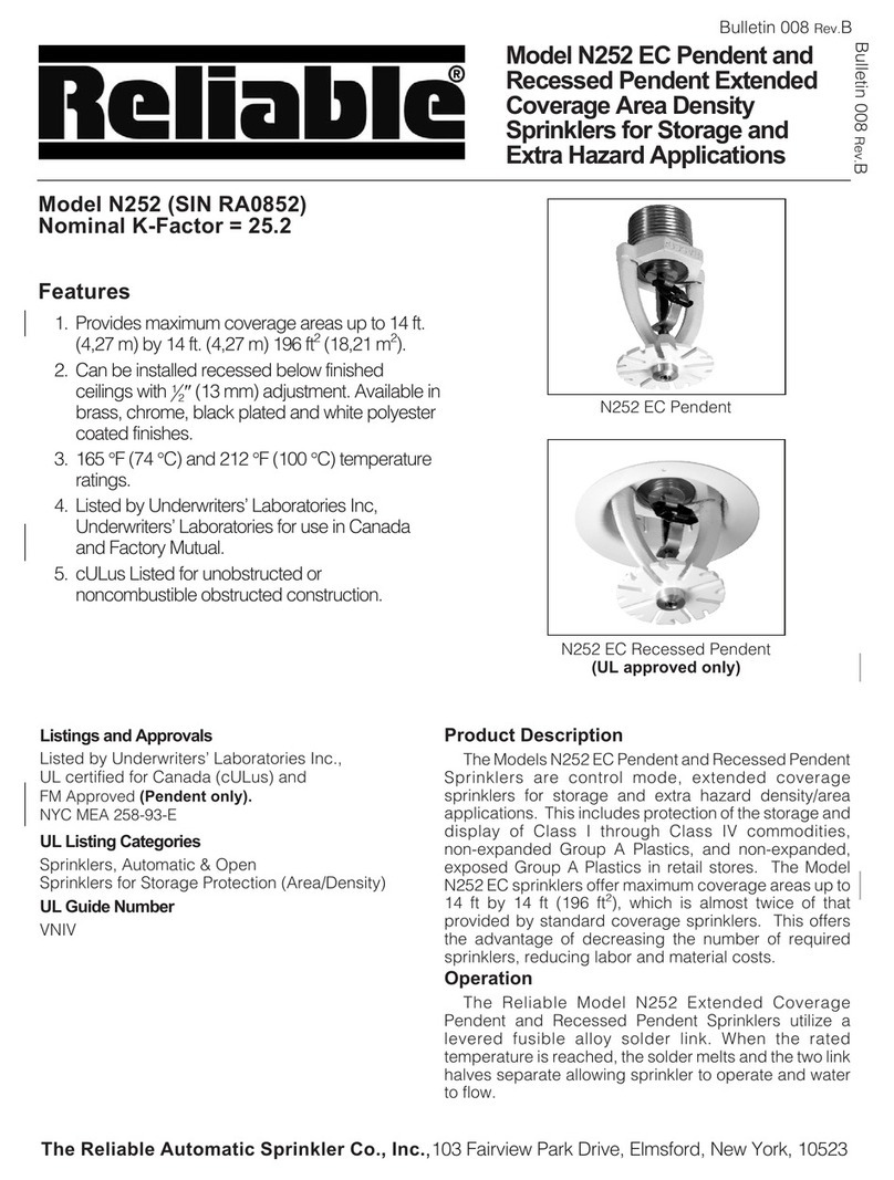
Reliable N252 EC Pendent User manual

Reliable

Reliable N252 EC Pendent User manual

Reliable DH56 Dry User manual

Reliable

Reliable DH56 Dry User manual

Reliable F156 Series User manual

Reliable

Reliable F156 Series User manual

Reliable F1FR User manual

Reliable

Reliable F1FR User manual
Reliable DH80 User manual

Reliable

Reliable DH80 User manual

Reliable F3QR56 User manual

Reliable

Reliable F3QR56 User manual
Popular Irrigation System manuals by other brands

Tyco rapid response LFII Series quick start guide

Tyco

Tyco rapid response LFII Series quick start guide

Johnson Controls tyco TY2334 manual

Johnson Controls

Johnson Controls tyco TY2334 manual

RainPoint ITV201P user manual

RainPoint

RainPoint ITV201P user manual

Orbit 27752 instruction manual

Orbit

Orbit 27752 instruction manual

Tyco Fire Product SIN S3244 manual

Tyco Fire Product

Tyco Fire Product SIN S3244 manual

Tyco ESFR-17 manual

Tyco

Tyco ESFR-17 manual

Tyco Fire Product CENTRAL TY-B instruction manual

Tyco Fire Product

Tyco Fire Product CENTRAL TY-B instruction manual

Toro ZSERIES 570Z brochure

Toro

Toro ZSERIES 570Z brochure

Orbit DripMaster Vegetable Garden Soaker System Step-by-step guide

Orbit

Orbit DripMaster Vegetable Garden Soaker System Step-by-step guide

Toro TR50 Instruction guide

Toro

Toro TR50 Instruction guide

claber 8053 instruction manual

claber

claber 8053 instruction manual

Tyco TY-FRB Series manual

Tyco

Tyco TY-FRB Series manual

Sime GEMINI Installation, use and maintenance

Sime

Sime GEMINI Installation, use and maintenance

Tyco Fire Product Star Luminous S178 instruction manual

Tyco Fire Product

Tyco Fire Product Star Luminous S178 instruction manual

Eden 94106EDAMZ manual

Eden

Eden 94106EDAMZ manual

Hunter ST Series owner's manual

Hunter

Hunter ST Series owner's manual

Sime POP-UP SPORTGUN INSTALLATION, USE, MAINTENANCE AND SPARE PARTS MANUAL

Sime

Sime POP-UP SPORTGUN INSTALLATION, USE, MAINTENANCE AND SPARE PARTS MANUAL

Tyco TY-B Series quick guide

Tyco

Tyco TY-B Series quick guide

manuals.online logo
manuals.online logoBrands
  • About & Mission
  • Contact us
  • Privacy Policy
  • Terms and Conditions

Copyright 2025 Manuals.Online. All Rights Reserved.