manuals.online logo
Brands
  1. Home
  2. •
  3. Brands
  4. •
  5. Renfert
  6. •
  7. Dental Equipment
  8. •
  9. Renfert Vario-Jet automatic User manual

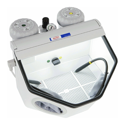
Renfert Vario-Jet automatic User manual

Vario-Jet automatic
No. 2961
Bedienungsanleitung
Instruction Manual • Mode d’emploi • Modo d’impiego
Instrucciones para el servicio • Handleiding
Renfert GmbH • Industriegebiet • 78247 Hilzingen
Germany • Tel. +49 7731 8208-0 • Fax +49 7731 8208-70
[email protected] • www.renfert.com
Made in Germany
102 21-9616
ENGLISH
Vario-Jet automatic
No. 2961
1. Introduction
We are delighted that you have decided to purchase the
Vario-Jet automatic recycling sandblaster. This unit sets
new standards with regard to function, efficiency, safety
and ergonomics.
Please note the following tips in order to ensure a long
and problem-free service life.
2. Description / Applications
The Vario-Jet automatic recycling sandblaster is for use in
dental laboratories in order to carry out the removal of
residual investment material and oxides from frameworks
(mainly model casting). It boasts a touch control pad that
is not affected by dirt and is sealed against dust in order
to ensure long and problem-free functioning.
The recycling sandblaster can be set to manual or auto-
matic mode dependent on choice. The construction of the
unit ensures excellent blasting efficiency within a short
period of time and uses comparatively less blasting mate-
rial (on average 100-300 g per hour, dependent on extrac-
tor unit). The funnel-shaped sand silo capacity of more
than 5 kg allows long periods free from interruption.
The parameters of working pressure, time, automatic /
manual and extraction On/Off + run-on time (via an exter-
nal unit) can be set on a sliding scale within the total
potential.
3. Installation / Operation
3.1 Set-up and Connection:
1. Remove all the parts found within the blasting
chamber and proceed as follows:
2. First decide whether the unit should be mounted on
the wall or simply set on the work bench. For wall
mounting, a drilling template and heavy load wall plug
set are supplied. Anchor the hooks on the wall.
Before hanging up the unit set up the connection leads
according to points 3 to 5. Mount the unit onto the
hooks via the openings on the back
3. Connect the compressed air to the unit (17) via the
blue connection hose and the connection set. Ensure
that the compressed air hose is not kinked. Then
connect the foot switch to the unit (13).
4. Set up the electrical connection to the unit using the
cable supplied (11). Please pay attention to the
voltage specified on the identification plate!
5. Connect the extraction hose to the extractor pipe at
the back of the unit (16).
When using a single-bench extraction unit connect the
electrical cable of your extraction unit to the plug (14)
on the back of the unit via the supplied adapter cable.
Set the extraction unit to continuous use mode on the
main switch. Please note the maximum allowable
connection power for extraction unit of 1200 W!
Your extraction unit will now be driven by the blasting
unit.
6. Attach the supplied blasting basket to the motor shaft
(22) by pressing down. Make sure that the supplied
hexagonal rubber mat is placed in the basket.
7. Remove the cable fastener (used to secure during
transport) from the blasting nozzle unit (25).
8. Fill the unit with approx. 5 kg of blasting material of
your choice by simply pouring it into the blasting
chamber. Maximum grain size should be 500 µm!
9. Close the glass lid as the unit will only work when it is
closed.
10.Check the required blasting pressure on the gauge (2)
and change the pressure if necessary via the pressure
reducer (1). Pull the knob out of the raster position to
re-set the blasting pressure.
11.Your unit is ready for use.
12.The use of additional compressed-air based units (jet
nozzles, fine sandblasting unit, deflasking chisel etc.)
within the blasting chamber is possible via the feeder
(20). The unit can be connected to the free adapter (19).
4. Operation
4.1 Quick overview of controls:
• On/Off switch – selection button (7)
• Selection switch for manual / automatic mode (5)
• Blasting time setting (automatic mode) – selection
buttons (3) from 1 to 60 minutes
• Manual On/Off switch for external extraction unit –
selection button (6)
• Setting for extraction unit run-on time – dial (21)
• Setting for blasting pressure – dial (1) from 1 to 6 bar
• Start button for automatic mode – selection button (10)
• Stop button for automatic mode – selection button (8)
• Pause button for automatic mode – selection button (9)
4.2 Automatic mode:
1. Put the cast objects into the basket and set the
required blasting pressure on the control (1). The
blasting nozzle unit (25) must be fixed to the holder.
2. Press the button (7) to switch on
the unit. It will go into automatic
mode. This is also visible via
the time displayed in the LED
display.
3. The time can be set from 1 to 60
minutes as required via the button (3).
This will be stored in the memory of the unit.
4. By pressing ”START” the Vario-
Jet will automatically begin the
blasting process i.e., the basket
will start turning, the extraction
unit will switch on and the unit
carries on for the programmed
amount of time. The time display flashes.
5. The blasting process can be
interrupted by pressing ”HOLD”
(9). The remaining time will
flash on the display. On re-
newing the start blasting will
continue for the remaining time.
During the pause you can work manually using the foot
switch.
6. By pressing ”STOP” (8) the blasting process will cease
regardless of whether you wanted to interrupt the pro-
cess or end it completely. The timer returns back to
the original time setting and is ready for use.
Tips & Tricks:
• Before blasting cast objects remove as much
investment material as possible
--> reduces necessary blasting time
• Remove any casting sprues
--> 50% improvement on blasting effect
• When blasting single objects place in casting
cones --> improves object rotation
4.3 Manual Mode:
1. Press the button (7) to switch on
the unit then press the button
(5) to switch the unit into
manual mode. The LED display
shows only the points.
2. The unit can now only be used
via the foot switch. The basket
will not function in manual mode.
3. The extraction unit will automatically start up when
blasting commences.
4. By re-pressing the button (5) the unit will switch back
into automatic mode.
5. The blasting nozzle unit (25) can be removed from its
holder in manual mode and be guided by hand.
4.4 Extraction Unit
1. The run-on time for the connected (14) extraction unit
can be infinitely varied between 5 and 30 seconds via
the dial (21) on the back of the unit.
2. By pressing the button (6) you can make the extraction
unit independent from the blasting process e.g., when
cleaning the unit. During the blasting process the ex-
traction unit cannot be manually switched off for safety
reasons.
3. On initial delivery the extraction unit is automatically
configured for Renfert’s extraction units. You can ope-
rate Renfert’s extraction units on the lowest setting.
Tips & Tricks:
During the extraction unit’s run-on time the set time
cannot be altered.
4.5 Warning Function:
The red LED (4) lights up when the glass screen is open
--> no blasting is possible! The display flashes.
4.6 Protective Ring on Basket:
At the inner side the basket is fitted with a protective
rubber band which prevents interlocking of the clasp
pieces in the perforated sides as well as early wear and
tear of the basket.
It is possible to remove the band, however it must be
reckoned on a higher wear and tear of the basket.
4.7 Removal of the Basket:
The basket can be easily removed for manual use of the
unit. Simply pull it forward off the shaft. Pull off using
both hands supported by a gentle shaking movement.
Now remove the basket from the blasting chamber. To
reposition press the basket onto the shaft until it clicks in
place. For improved central positioned the rubber mat
can be removed before repositioning. The shaft is visible
through an opening in the basket.
4.8 Distance between Jet Nozzle Unit and Basket:
The distance between the blasting nozzle unit (25) and
the basket, and thus to the objects to be blasted, can be
set in three levels. The standard level positions the blas-
ting nozzle unit (25) in the middle. To set for specific uses
pull the blasting nozzle unit (25) out of its holder and posi-
tion it according to your needs.
Tips and Tricks:
The blasting nozzles can be set to three levels:
• Position 1: least distance to basket
--> for regular blasting of 1-2 objects
• Position 2: middle distance to basket
--> for regular blasting of 3-5 objects
• Position 3: greatest distance to basket
--> for regular blasting of 5 or more objects
5. Areas of Caution
• Never operate a sandblaster without a suitable
dust extraction unit or suitable personal pro-
tective clothing as this can be detrimental to
your health. The type of dust extractor must
relate to the type of dust produced by your
sandblasting work. It is imperative to adhere to
the legal regulations (in Europe this means EN
60335-2-69).
• Before operating check the electrical and
pneumatic leads for damage.
• If defects are found do not activate or continue
to use the unit.
• Before opening the unit remove the plug from
the socket.
• Before changing the fluorescent lamp make
sure it is unplugged.
• Do not push the lamp too hard (danger of brea-
kage!). Wear gloves or use a protective cloth!
• Do not sandblast unprotected skin
--> danger of injury!
• Before connecting the unit check the voltage
against that on the unit ID.
• The unit interrupts blasting when the protective
glass is open. Do not readjust the switch.
Escaping blasting material may cause eye
injury.
5.1 Exclusion of liability
Renfert GmbH rejects any claims for compensation
as well as warranty claims in case of:
• the product is used for any other purpose than
those mentioned in the instruction manual
• the product is changed or amended in any way
beyond those mentioned in the instruction
manual
• the product is repaired by a non-authorized party
or the product is not fitted with original Renfert
replacement parts
• the product is used continuously despite visible
safety faults
6. Cleaning / Maintenance
From time to time your Vario Jet automatic will need
maintenance. This consists of checking the connection
leads and pipes for seals and damage as well as
cleaning the plate.
Use only solvent-free cleaning fluid when cleaning (e.g.
soapy water).
6.1 Condensed Water:
Occasionally check whether water has formed in the
maintenance unit. If so, press the drainage valve (18) on
the maintenance unit.
6.2 Removal of blasting residue via the drawer:
Open the hinges (26) after pressing the red bolt clip.
Take out the drawer and dispose of the blasting residue.
On re-inserting the drawer take care that the sand guide
pipe lies in the back left corner and is not squashed.
Place the hinges so that the hinge nose can be pulled into
the holder (27). Now close the hinges until the hinge nose
clicks into place.
6.3 Changing the Blasting Material:
To change the blasting material stand the unit on the
table and pull it slightly over the edge of the table until the
drainage lid on the bottom of the unit is visible.
Place a suitable vessel underneath this opening and
loosen both knurled screws to let out the sandblasting
material.
Tighten the lid again using the knurled screws and check
that the sieve at the base of the sand silo has no impuri-
ties in it (if it does remove them).
Fill with new sandblasting material.
Tips & Tricks:
Long-term tests have shown that optimum blasting
efficiency is achieved with 125 µm grain size.
6.4 Changing the Nozzles:
Using a hexagon key (contained in small parts set)
loosen the thread on the blasting nozzle unit (25) and
pull out the nozzle holder from the unit. To replace the
nozzle carry out the above process in reverse. Make sure
that before you replace the new nozzle all parts are free
from sandblasting material in order to guarantee perfect
functioning of the unit.
6.5 Changing the Viewing Pane:
Loosen the crosshead screws on the top hinge. Remove
the pane. The new pane can now be easily mounted by
feeding it through the upper holder from one side and then
carefully tightening the crosshead screws. Make sure the
coated side of the pane is facing into the chamber!
Note: The slight dents in the glass coating will disappear
after a short time.
Tips and Tricks:
Occasionally clean the inside of the pane using a
damp cloth in order to remove the cloudiness
caused by fine dust.
Fig. 1 Fig. 2
Fig. 3 Fig. 4
6.6 Changing the Fluorescent Lamp:
Unplug the mains cable and pull down the fluorescent lamp
out of its clamps (Fig. 1+2). Now completely remove the
protective pipe from its socket (move to the right) and
take out the fluorescent lamp (Fig. 3). Replace the lamp
by carrying out the above process in reverse. Make sure
that the fluorescent pipe is fed correctly into the rubber
holder in the protective pipe (Fig. 4) and that the reflector
is positioned correctly. In order to guarantee perfect func-
tioning of the unit you should also make sure that no
blasting material get into the lamp. Only use original
lights with integrated starter and 11 Watt power (see
replacement parts list)!
When changing the lamp do not bend it (danger of
breakage!). Wear gloves or use a cloth to avoid glass
splinters.
6.7 Changing the Hose within the Blasting
Chamber:
The blasting hoses are prone to natural wear and tear and
must, therefore, occasionally be replaced.
Disconnect the Vario-Jet from the compressed air supply
and loosen the screw cap on the screw at the back of the
blasting chamber. Make sure when replacing the new
hose that the caps are fastened tightly. Only use Renfert
replacement hose!
7. Spare Parts
You will find the order numbers for wear and tear / spare
parts in the list supplied.
8. Guarantee
When used properly Renfert guarantees all parts of the
Vario-Jet automatic - with the exception of wear and tear
parts - for 3 years. Parts given to natural wear and tear
are excluded from this guarantee (e.g. blasting nozzles,
blasting hose, lighting, connections for blasting hose,
viewing pane, filter materials etc.).
The guarantee is void for damage caused by misuse, dis-
regard of the instruction manual, cleaning, maintenance
and connection, for self-repaired units or repair by un-
trained personnel, for use of spare parts from other manu-
facturers and on influences outside the normal practice or
unauthorised in the instruction manual. Services under
guarantee do not extend the guarantee.
9. Technical Specifications
Working pressure: 1-6 bar (14.5-87 psi)
Connecting pressure: max. 10 bar (145 psi)
Air consumption: 200l/min at 6 bar (87 psi)
Voltage (pre-set by Renfert): 120/230/240 V, 50-60 Hz
Power consumption: 30 W
Max. connecting power of extractor unit: 1200 W
Power consumption (lamp): 11 W
Size of connection point for external extraction unit:
40 x 2.5 mm (1.5 in.)
Dimensions WxHxD: 405 x 650 x 440 mm
(16“ x 24“ x 17“)
Weight (unfilled): approx. 28.5 kg (60 lbs)
Noise level according to DIN 45635-01-KL3: < 72 dB(A)
10. Parts supplied
1Vario-Jet automatic blasting unit
1 foot switch, electric
1 connector lead
1 connector pipe for compressed air system
1 connector set
1 small parts set with drilling template
1 instruction manual
1 spare parts list
11. Units available
No. 2961-0000 Vario-Jet automatic, 230 V
No. 2961-1000 Vario-Jet automatic, 120 V
No. 2961-2000 Vario-Jet automatic, 240 V
12. Accessories
Renfert supplies the following abrasive materials suitable
with the Vario-Jet:
Cobra aluminium oxide
No. 1594-1205 50 µm, white 5 kg canister
No. 1594-2201 50 µm, white 25 kg sack
No. 1584-1005 90 µm, white 5 kg canister
No. 1583-1005 110 µm, white 5 kg canister
No. 1583-2000 110 µm, white 25 kg sack
No. 1587-1005 125 µm, pink 5 kg canister
No. 1587-2000 125 µm, pink 25 kg sack
No. 1585-1005 250 µm, white 5 kg canister
No. 1585-2000 250 µm, white 25 kg sack
Rolloblast glass beads
No. 1594-1305 50 µm 5 kg canister
No. 1594-2301 50 µm 25 kg sack
No. 1589-1005 100 µm 5 kg canister
Satinat
No. 1595-1005 50 µm 5 kg canister
Fault
Unit doesn’t blast, warning lamp
flashing.
Air flow present but no sand
coming through.
No air, no sand.
On/Off switch doesn’t work.
Basket shakes, doesn’t move.
Blasting chamber gets too dusty.
Consumption of blasting material
too high.
Objects fall out of the basket.
Blasting time too long / reduced
blasting effect.
Extraction unit still runs even
when blasting has been
interrupted.
Heavy dust build-up during
blasting.
Cause
• Glass pane is not closed.
• Magnet (24) is missing.
• Protective switch is defect.
• Amount of sand too low.
• Filter on suction point of suction
pipe is blocked.
• Suction pipe defect.
• Nozzle is blocked.
• No power connection.
• Unit fuse is defect.
• Basket is stuck mechanically.
• Too little suction power.
• Extraction unit blocked.
• Suction power is too high.
• Too many objects.
• The blasting cones are sheltering
the objects.
• Too little working pressure.
• Too great distance from nozzle.
• Too little blasting material in unit.
• Blasting material lead pipe is
blocked / defect.
• Blasting nozzle is split.
• Air power of the compressor is too
low.
• A certain run-on time is normal in
order to remove any dust still
present in the chamber.
• The switch for the external
extraction unit (6) was reactivated.
• No extraction unit connected.
• Extraction power too weak.
Remedy
• Close the pane.
• Replace the magnet (see spare
parts list).
• Exchange during service.
• Fill with more sand.
• Clean the filter.
• Exchange the suction pipe.
• Open the blasting nozzle unit (25)
and clean the nozzle.
• Connect to the power supply.
• Change fuse (12+15). Replacement
fuse in set. If it happens again
--> repair.
• Release by removing and replacing
the basket.
• Raise suction power on extraction
unit.
• Raise suction power by closing the
air holes (23) under the pane
holder (use sticky tape).
• Clean extraction unit.
• Reduce suction power.
Warning: too little suction power
can lead to dirty blasting material.
• Reduce to a maximum of 6 objects.
• Remove blasting cones before
starting.
• Increase working pressure
(recommended working pressure:
4-5 bar).
• Move nozzle further forward.
• Unit should be filled with min. 4-5
kg blasting material.
• Remove sand and check / replace
lead pipe.
• Replace nozzles.
• Dehydrate the compressor. Use a
more powerful unit.
• Regulate the run-on time between
5 and 30 seconds via the control on
the back of the unit.
• Switch off the external extraction
unit.
• Connect an extraction unit.
• Close the air holes (23).
• Increase extraction power.
13. Troubleshooting Guide
Fault
Switch for external extraction
does not work.
Foot switch doesn’t work.
Extraction unit doesn’t work.
Pulsating sand flow.
Independent switching off while
working.
Cause
• Extraction unit is not controlled by
blasting unit.
• Unit is in automatic mode.
• Extraction unit is not controlled by
the sandblasting unit.
• Extraction unit is not switched to
continuous mode.
• Fuse (15) for extraction unit is
defect.
• Blasting material is used or too
impure.
• Too low supply voltage.
• Inadequate grounding because
the device is located too far from
the nearest ground connection.
Remedy
• Connect the extraction unit power
cable to the blasting unit.
• Interrupt automatic mode using
HOLD button (9).
• Switch to manual (5).
• Connect the extraction unit power
cable to the blasting unit.
• Switch the extraction unit to
continuous mode.
• Change the fuse (15) - replacement
fuse found in set. If it happens
again --> repair.
• Renew blasting material.
• Checking of the power capacity of
the mains supply.
• Temporary switching off of other
more powerful units.
• Decrease the distance to the
nearest ground connection.
Subject to modification.
14
15
13
11
12
1 2 3
9 810
654 7
16 17 18 19
20
26 27
21
23
22
25
24
EG-Konformitätserklärung
RenfertGmbH,Industriegebiet, 78247Hilzingen
Hiermiterklärenwir, daßdie Bauart desUmlaufstrahlgerätes
Vario-Jet folgendeneinschlägigenBestimmungen inder jeweils
gültigenVersionentspricht:
EG-Richtlinie EMV (89/336/EWG)
EG-Richtlinie Maschinen (89/392/EWG) i.d.F. 98/38 EWG
EG-RichtlinieelektrischeBetriebsmittel zurVerwendung
innerhalbbestimmterSpannungsgrenzen (73/23/EWG)
Angewendeteharmonisierte Normen:
EN 292 T.1; EN 292T.2; EN 60204 T.1; EN 50082-1;
EN 55011; EN 50081-1; DIN EN 61000-4-2;
DIN EN 61000-4-3; DIN EN 61000-4-4; DIN EN
61000-4-5; DIN EN 61000-4-6; DIN EN 61000-4-11
AngewendetenationaleSpezifikationen: DIN45635T.1
_____________________________
MichaelPreuß,Konstruktionsleiter Hilzingen, 20.03.00
Declaration of CE Conformity
RenfertGmbH,Industriegebiet, 78247Hilzingen
We herewith confirm that the construction of the Vario-Jet
sandblastercomplieswith thefollowingnorms:
EC Directive on EMC (89/336/EEC)
EC Directive on Machines (89/392/EEC), Vers. 98/38/EEC
EC Directive on Electrical Equipment for Use Within Certain
VoltageRanges (73/23/EEC)
Harmonisednormsapplied:
EN 292 T.1; EN 292T.2; EN 60204 T.1; EN 50082-1;
EN 55011; EN 50081-1; DIN EN 61000-4-2;
DIN EN 61000-4-3; DIN EN 61000-4-4; DIN EN
61000-4-5; DIN EN 61000-4-6; DIN EN 61000-4-11
National specifications applied: DIN 45635 T.1
_____________________________
Michael Preuß, Head of Construction Hilzingen,20.03.00
Déclaration de conformité CE
RenfertGmbH,Industriegebiet, 78247Hilzingen
Nous assurons que le type de construction de la sableuse
automatique Vario-Jet est conformeauxnormes:
Directive CE sur la CEM (89/336/CEE)
DirectiveCE surlesmachines
(89/392
/CEE),vers. 98/38/CEE
Directive CE sur les moyens d'exploitation électriques desti-
nés à l'utilisation à l'intérieur de certaines limites de tension
73/23/CEE
Normesharmoniséesutilisées:
EN 292 T.1; EN 292T.2; EN 60204 T.1; EN 50082-1;
EN 55011; EN 50081-1; DIN EN 61000-4-2;
DIN EN 61000-4-3; DIN EN 61000-4-4; DIN EN
61000-4-5; DIN EN 61000-4-6; DIN EN 61000-4-11
Spécifications nationales apliquées: DIN45635T.1
_____________________________
MichaelPreuß,Chef de construction Hilzingen,20.03.00
Verklaring van EG-conformiteit
RenfertGmbH,Industriegebiet, 78247Hilzingen
Bijdezenverklaren wijdatde constructievande zandstraler
Vario-Jetaan devolgende normenvoldoet:
EG-richtlijn EMV (89/336/EG)
EG-richtlijn machines (89/392/EG) - 98/38 EG
EG-richtlijn elektrische produktiemiddelen voor
gebruik binnen bepaalde spanningslimieten
(73/23/EG)
Geharmoniseerdenormendie vantoepassing zijn:
EN 292 T.1; EN 292T.2; EN 60204 T.1; EN 50082-1;
EN 55011; EN 50081-1; DIN EN 61000-4-2;
DIN EN 61000-4-3; DIN EN 61000-4-4; DIN EN
61000-4-5; DIN EN 61000-4-6; DIN EN 61000-4-11
Duitse normen die van toepassing zijn: DIN 45635 T.1
_____________________________
MichaelPreuß,chef Constructie Hilzingen,20.03.00
Dichiarazione di conformità
secondo le norme della C.E.
RenfertGmbH,Industriegebiet, 78247Hilzingen
Conlapresente dichiariamochela costruzionedella sabbiatrice
Vario-Jet corrispondeallenorme seguenti:
DirettivaCE sullacompatibilitàelettromagnetica
(89/336/CE)
Direttiva CE sui macchinari (89/392/CEE) nella versione
98/38/CEE
Direttiva CE sulle apparecchiature elettriche da usare entro
determinati limiti di tensione 73/23/CEE
Normearmonizzateapplicate:
EN 292 T.1; EN 292T.2; EN 60204 T.1; EN 50082-1;
EN 55011; EN 50081-1; DIN EN 61000-4-2;
DIN EN 61000-4-3; DIN EN 61000-4-4; DIN EN
61000-4-5; DIN EN 61000-4-6; DIN EN 61000-4-11
Norme tedesche applicate: DIN45635 T.1
_____________________________
Michael Preuß, Caporeparto costruzione Hilzingen, 20.03.00
Declaración de conformidad
según la C.E.
RenfertGmbH,Industriegebiet, 78247Hilzingen
Porlapresente declaramosquela construccióndelaparatode
chorreado Vario-Jet correspondealas siguientesprescripciones
pertinentes:
NormaCEcompatibilidadelectromagnética(89/336/CEE)
Norma CE máquinas (89/392/CEE) versión 98/38 CEE
Norma CE medios de producción eléctricos para la utiliza-
ción dentro de límites de tensión determinados 73/23/CEE
Normasarmonizadasque hansido aplicadas:
EN 292 T.1; EN 292T.2; EN 60204 T.1; EN 50082-1;
EN 55011; EN 50081-1; DIN EN 61000-4-2;
DIN EN 61000-4-3; DIN EN 61000-4-4; DIN EN
61000-4-5; DIN EN 61000-4-6; DIN EN 61000-4-11
Especificacionesnacionales quehansidoaplicadas:
DIN 45635T.1
_____________________________
Michael Preuß, Jefe de Construcción Hilzingen,20.03.00

This manual suits for next models

1

Other Renfert Dental Equipment manuals

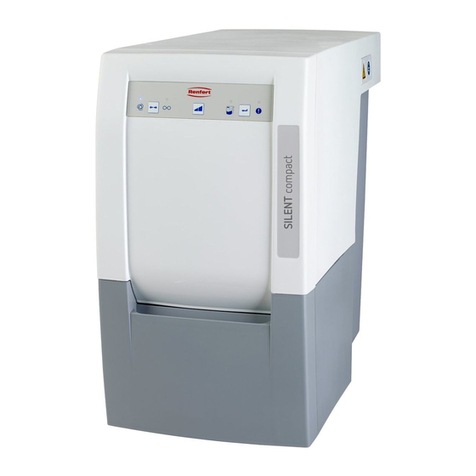
Renfert SILENT compact Reference guide

Renfert

Renfert SILENT compact Reference guide

Renfert EASY view+3D User manual

Renfert

Renfert EASY view+3D User manual

Renfert POWER User manual

Renfert

Renfert POWER User manual

Renfert SIMPLEX sliceware User manual

Renfert

Renfert SIMPLEX sliceware User manual

Renfert Waxlectric light I User manual

Renfert

Renfert Waxlectric light I User manual

Renfert Duomix II User manual

Renfert

Renfert Duomix II User manual

Renfert SYMPRO User manual

Renfert

Renfert SYMPRO User manual

Renfert hotty Installation guide

Renfert

Renfert hotty Installation guide

Renfert Twister evolution Operating and installation instructions

Renfert

Renfert Twister evolution Operating and installation instructions

Renfert MT plus User manual

Renfert

Renfert MT plus User manual

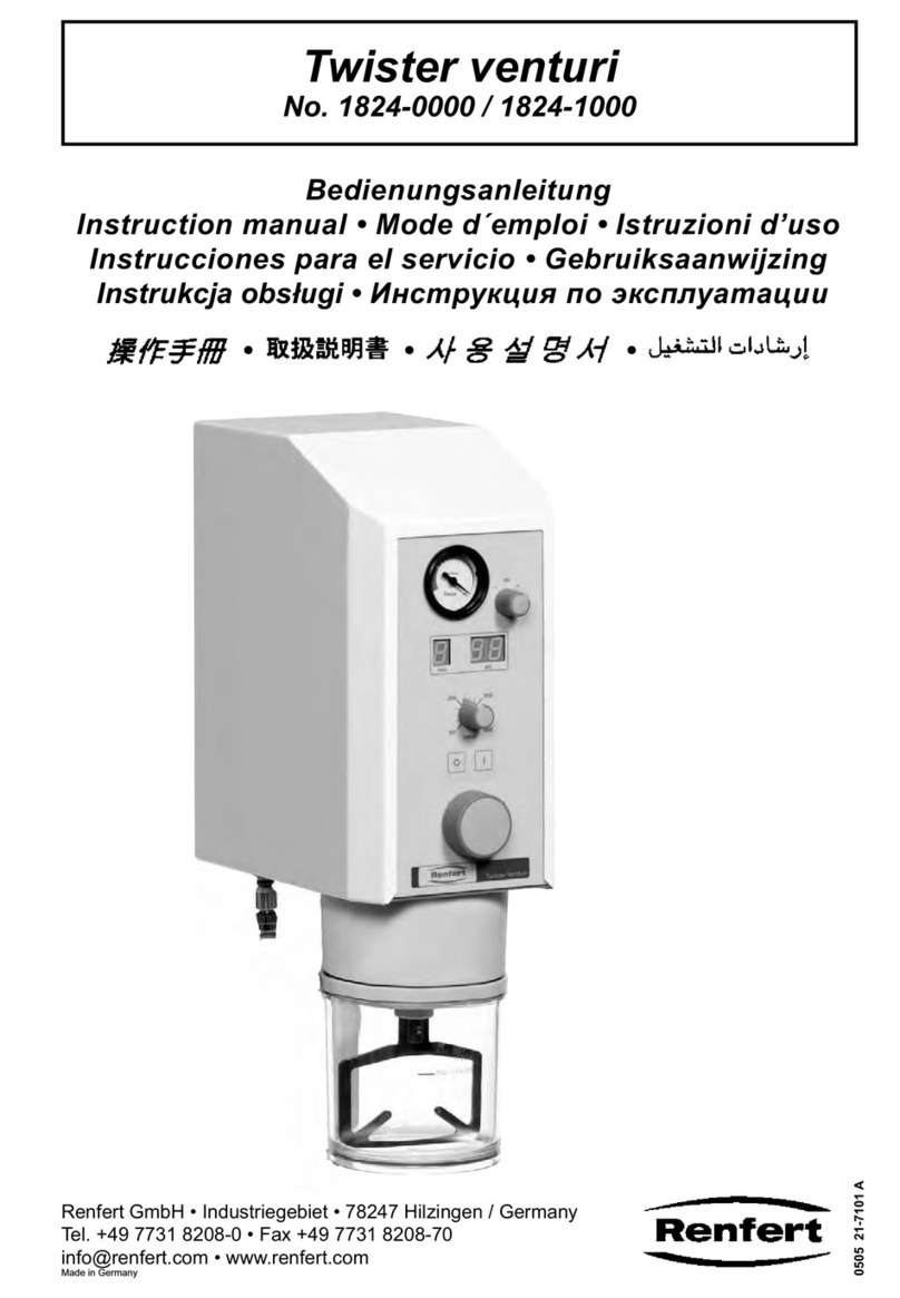
Renfert Twister venturi User manual

Renfert

Renfert Twister venturi User manual

Renfert Vario basic Installation guide

Renfert

Renfert Vario basic Installation guide

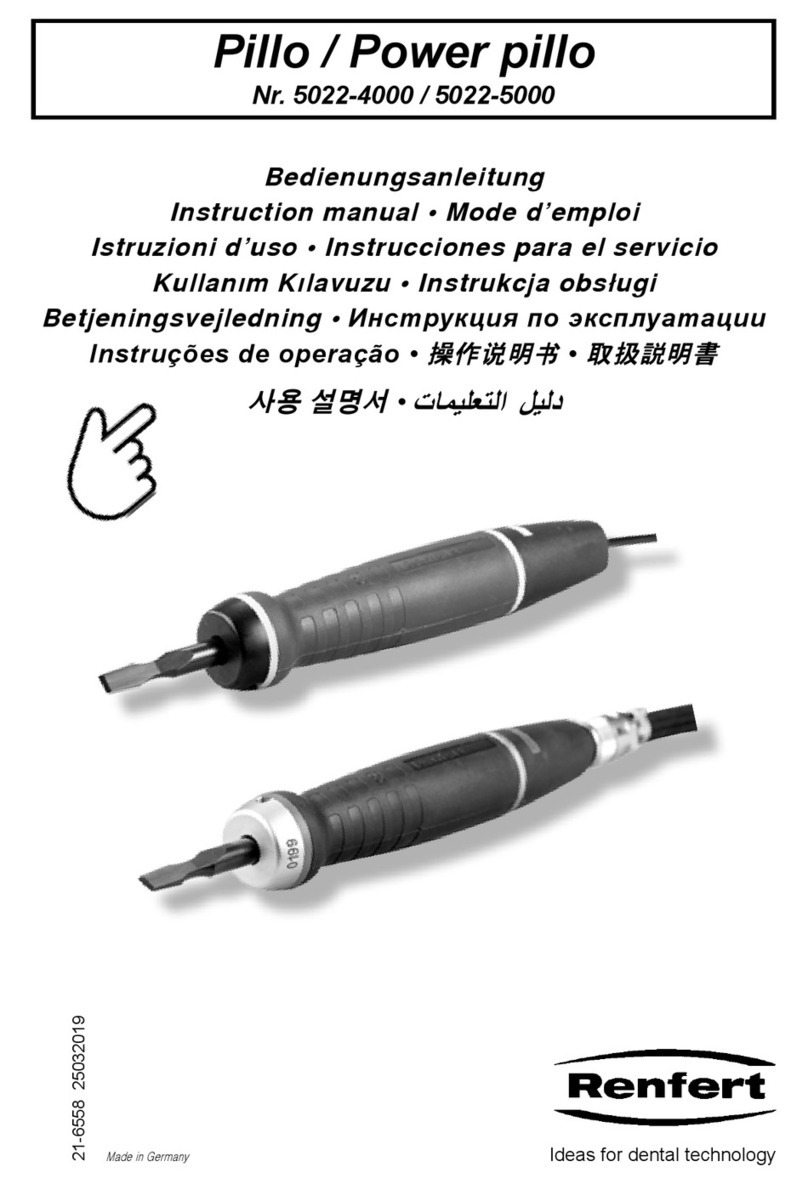
Renfert Power-Pillo User manual

Renfert

Renfert Power-Pillo User manual

Renfert TOP spin User manual

Renfert

Renfert TOP spin User manual

Renfert Sympress 6000-0000 User manual

Renfert

Renfert Sympress 6000-0000 User manual

Renfert Waxlectric light I User manual

Renfert

Renfert Waxlectric light I User manual

Renfert Waxlectric light I Installation guide

Renfert

Renfert Waxlectric light I Installation guide

Renfert MT 2 User manual

Renfert

Renfert MT 2 User manual

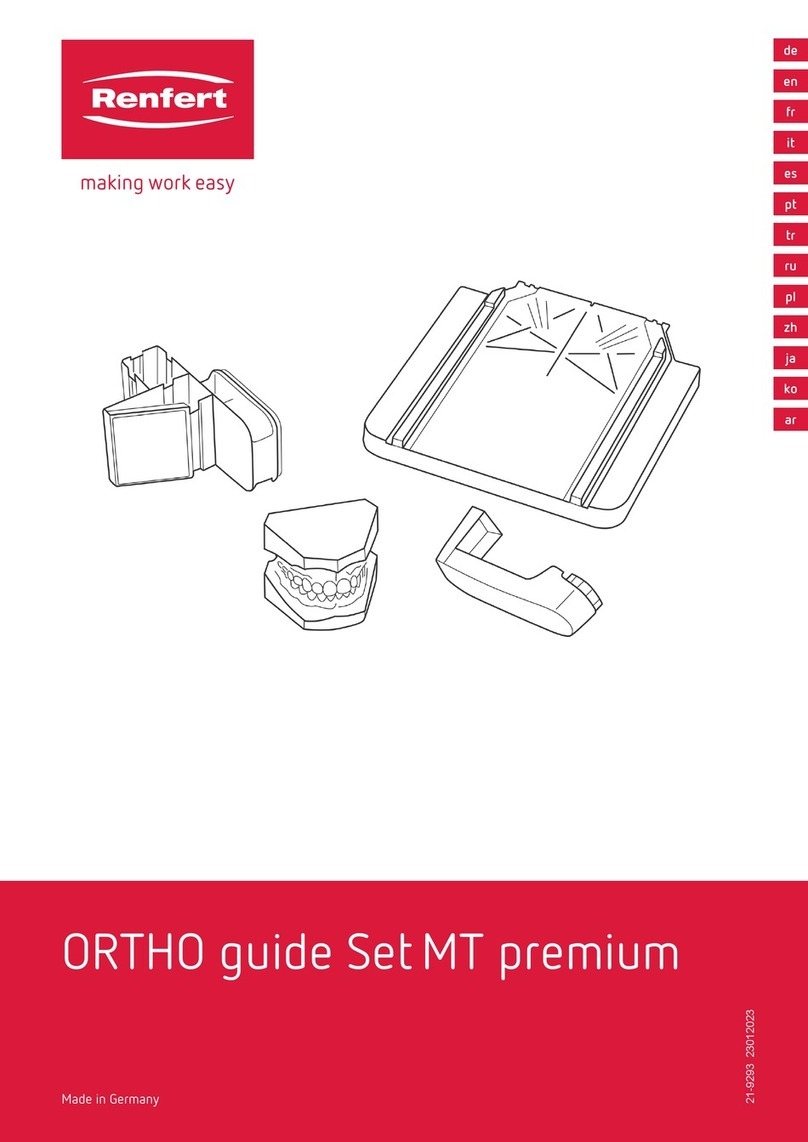
Renfert ORTHO guide Set MT premium User manual

Renfert

Renfert ORTHO guide Set MT premium User manual

Renfert Waxlectric light I User manual

Renfert

Renfert Waxlectric light I User manual

Renfert Vibrax Installation guide

Renfert

Renfert Vibrax Installation guide

Renfert Waxlectric light I User manual

Renfert

Renfert Waxlectric light I User manual

Renfert SYMPRO Quick guide

Renfert

Renfert SYMPRO Quick guide

Renfert MT plus User manual

Renfert

Renfert MT plus User manual

Popular Dental Equipment manuals by other brands

DENTSPLY DeTrey SmartLite PS manual

DENTSPLY

DENTSPLY DeTrey SmartLite PS manual

parkell TurboSENSOR D560-110 Instructions for use

parkell

parkell TurboSENSOR D560-110 Instructions for use

Dentsply Sirona Midwest Stylus Plus operating instructions

Dentsply Sirona

Dentsply Sirona Midwest Stylus Plus operating instructions

Danville PrepStart Operator's manual

Danville

Danville PrepStart Operator's manual

Amanngirrbach ceramill matik Maintenance instructions

Amanngirrbach

Amanngirrbach ceramill matik Maintenance instructions

Den-Mat Sapphire plus Instructions for use

Den-Mat

Den-Mat Sapphire plus Instructions for use

Amanngirrbach Ceramill Map300 user manual

Amanngirrbach

Amanngirrbach Ceramill Map300 user manual

Belmont Quolis Series Installation and operation instructions

Belmont

Belmont Quolis Series Installation and operation instructions

KaVo Kerr DEXIS CariVu quick start guide

KaVo Kerr

KaVo Kerr DEXIS CariVu quick start guide

SAESHIN TRAUS ATN400 instruction manual

SAESHIN

SAESHIN TRAUS ATN400 instruction manual

BG Light BLUEDENT 12 BL Operating instructions manual

BG Light

BG Light BLUEDENT 12 BL Operating instructions manual

VERDER Carbolite Gero CDF 15/1b Installation, operation & maintenance instructions

VERDER

VERDER Carbolite Gero CDF 15/1b Installation, operation & maintenance instructions

MITSUI Kulzer Dynamix speed Instructions for use

MITSUI

MITSUI Kulzer Dynamix speed Instructions for use

EMS PIEZON EN-060 quick start guide

EMS

EMS PIEZON EN-060 quick start guide

Zhermack hurrimix 2 user manual

Zhermack

Zhermack hurrimix 2 user manual

Maxray DX3000 user manual

Maxray

Maxray DX3000 user manual

Dexcowin DX-7017 user manual

Dexcowin

Dexcowin DX-7017 user manual

BrightTonix Y10 Step-by-Step

BrightTonix

BrightTonix Y10 Step-by-Step

manuals.online logo
manuals.online logoBrands
  • About & Mission
  • Contact us
  • Privacy Policy
  • Terms and Conditions

Copyright 2025 Manuals.Online. All Rights Reserved.