Renishaw PI 200 User manual

-~
ARTISAN
®
~I
TECHNOLOGY
GROUP
Your definitive source
for
quality
pre-owned
equipment.
Artisan Technology
Group
Full-service,
independent
repair
center
with
experienced
engineers
and
technicians
on staff.
We
buy
your
excess,
underutilized,
and
idle
equipment
along
with
credit
for
buybacks
and
trade-ins
.
Custom
engineering
so
your
equipment
works
exactly as
you
specify.
•
Critical
and
expedited
services
•
Leasing
/
Rentals/
Demos
• In
stock/
Ready-to-ship
•
!TAR-certified
secure
asset
solutions
Expert
team
ITrust
guarantee
I
100%
satisfaction
All
tr
ademarks,
br
a
nd
names, a
nd
br
a
nd
s a
pp
earing here
in
are
th
e property of
th
e
ir
r
es
pecti
ve
ow
ner
s.
Visit our website - Click HERE

Installation guide
H-1000-5029-05-B
PI 200 interface for the TP200 system

© 2002 - 2007 Renishaw plc. All rights reserved.
Renishaw® is a registered trademark of Renishaw plc.
This document may not be copied or reproduced in whole or in part, or
transferred to any other media or language, by any means, without the
prior written permission of Renishaw.
The publication of material within this document does not imply
freedom from the patent rights of Renishaw plc.
Disclaimer
Considerable effort has been made to ensure that the contents of
this document are free from inaccuracies and omissions. However,
Renishaw makes no warranties with respect to the contents of this
document and specifically disclaims any implied warranties. Renishaw
reserves the right to make changes to this document and to the
product described herein without obligation to notify any person of
such changes.
Trademarks
All brand names and product names used in this document are trade
names, service marks, trademarks, or registered trademarks of their
respective owners.
Renishaw part no: H-1000-5029-05-B
Issued: 10 2007

1
PI 200
interface for TP200 probe system
installation guide

2
FCC
Information to user (FCC section 15.105)
This equipment has been tested and found to comply with the limits for a Class A digital
device, pursuant to Part 15 of the FCC rules. These limits are designed to provide
reasonable protection against harmful interference when the equipment is operated
in a commercial environment. This equipment generates, uses, and can radiate radio
frequency energy and, if not installed and used in accordance with the instruction
manual, may cause harmful interference to radio communications. Operation of this
equipment in a residential area is likely to cause harmful interference, in which case
you will be required to correct the interference at your own expense.
Information to user (FCC section 15.21)
The user is cautioned that any changes or modifications not expressly approved by
Renishaw plc or authorised representative could void the user’s authority to operate the
equipment.
Special accessories (FCC section 15.27)
The user is also cautioned that any peripheral device installed with this equipment
such as a computer, must be connected with a high-quality shielded cable to insure
compliance with FCC limits.
TÜV
This equipment has been independently certified by TÜV Product Services in
accordance with OSHA (US) and SCC (Canada) requirements to the standards
UL61010-1 Second Edition and CAN/CSA-C22-2 No. 61010-1 Second Edition.

3
Care of equipment
Your Renishaw probe and accessories are precision instruments. Please use and
maintain the products in accordance with these instructions. Retain the transit box for
storing the components when not in use.
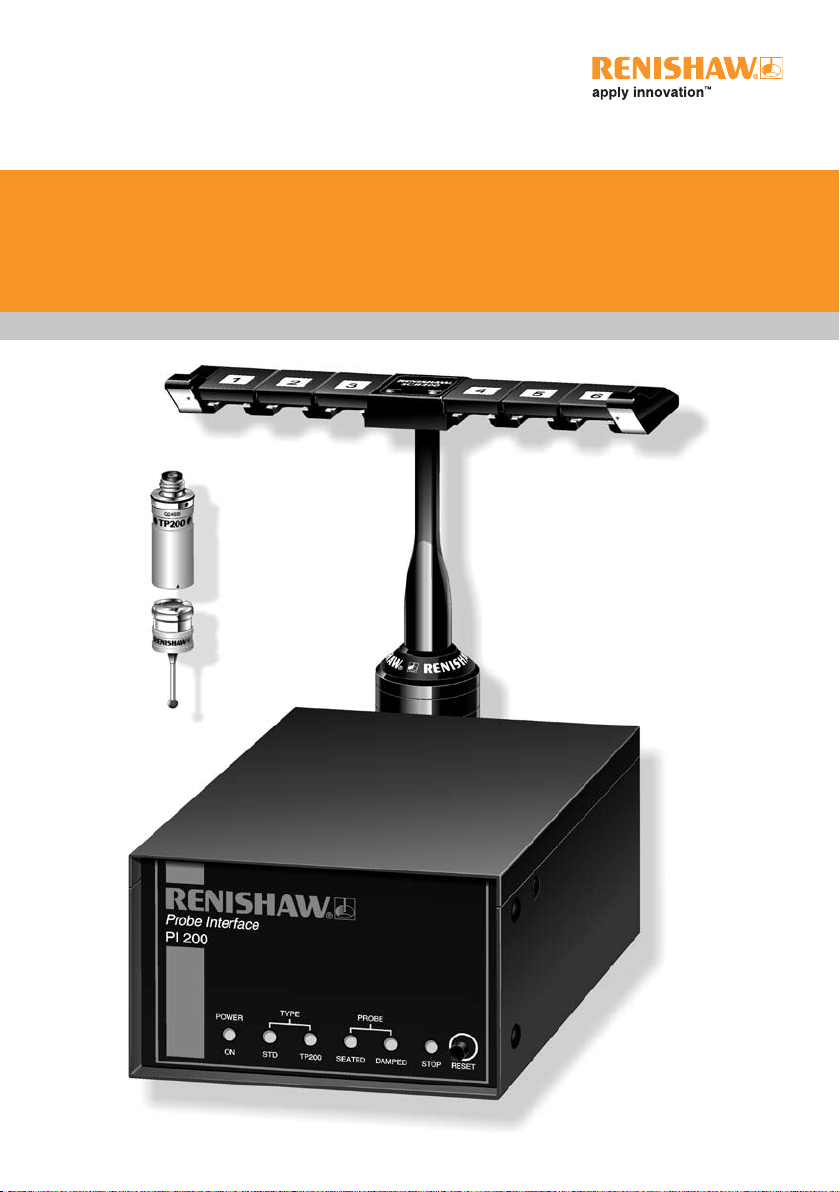
CAUTION: The TP200 probe contains sensitive strain sensors. Permanent
damage may be caused if the probe is dropped or subjected to severe shock
as may be caused by misuse.
Changes to Renishaw products
Renishaw plc reserves the right to improve, change or modify its hardware or software
without incurring any obligations to make changes to Renishaw equipment previously
sold.
Warranty
Renishaw plc warrants its equipment provided that it is installed exactly as defined in
associated Renishaw documentation.
Consent must be obtained from Renishaw if non-Renishaw equipment (e.g. interfaces
and/or cabling) is used or substituted. Failure to comply with this will invalidate the
Renishaw warranty.
Claims under warranty must be made from authorised services centres only, which may
be advised by the supplier or distributor.
Patents
Aspects of the TP200 system and aspects of similar systems are the subjects of the
following patents and patent applications:
EP 0243766 JP 2,545,082 US 4813151 US 5,755,038
EP 0388993 JP 2,539,824 US 4817362 US 5,918,378
EP 242747 B JP 2,647,881 US 4916339 US 6012230
EP 279828 B JP 3,004,050 US 5,228,352
EP 0470234 JP 3,346,593 US 5,327,657
EP 0521703 JP 3,294,269 US 5,404,649
EP 548328 B JP 3,279,317 US 5,339,535
EP 566719 B JP 2,510,804 US 5,323,540
EP 0501710 JP 3,634,363 US 5,505,005
EP 0641427 JP 3,018,015 US 5,671,542
EP 0392660 JP 3,546,057 US 4769919
EP 0740768 US 5,088,337 WO 97/35164
Care of equipment
!

4Safety
Safety
If this product is not used in its intended manner, any protection provided may be
impaired.
There are no user serviceable parts inside this equipment.
The PI 200 interface unit must be connected to a supply incorporating a protective
earth conductor via a three-core mains cable (line cord).
Electrical ratings
Supply voltage range 100 - 240 V ac + 10%, -15%
Power frequency range 47 Hz - 63 Hz
Power consumption 10 W
SSR contact ratings ±50 V pk. ±40 mA pk.
Operating conditions
The PI 200 interface unit is specified to operate under the following conditions as
defined in BS EN 61010-1:2001.
Protection provided by
enclosure
IP30
Altitude Maximum 2000 m
Operating temperature 0 °C to +50 °C
Storage temperature -10 °C to +70 °C
Relative humidity Maximum 80% RH up to +31 °C, decreasing
linearly to a maximum 50% at +40 °C.
Transient overvoltage Installation category II
Pollution degree 2
The PI 200 is isolated from AC power by disconnection of the IEC mains connector on
the rear panel. If any additional means of isolation is required, it must be specified and
fitted by the machine manufacturer or the installer of the product. The isolator must
be sited within easy reach of the CMM operator and comply with IEC61010 and any
applicable national wiring regulations for the country of installation.

5
Contents
Contents
1 Introduction ................................................................................................................7
2 Product description ....................................................................................................9
2.1 System overview ............................................................................................9
2.2 Probe status signal (SYNC)............................................................................9
2.3 Trigger confirmation signal (HALT) ...............................................................10
2.4 SYNC and HALT debounce..........................................................................12
2.5 Probe damped signal (PDAMP)....................................................................13
2.6 Stylus mass and ambient temperature compensation..................................14
2.7 RESET button...............................................................................................14
2.8 Front panel indicators ...................................................................................15
2.9 Audible indicator ...........................................................................................16
2.10 Rear panel switches and connectors............................................................16
2.11 Configuration switches..................................................................................17
2.12 Probe polarity switch ....................................................................................21
3 Connector pin-outs ..................................................................................................22
3.1 PICS input connector....................................................................................22
3.2 PICS output connector .................................................................................23
3.3 Solid state relay (SSR) output connector .....................................................24
3.4 Stylus change rack (SCR) output connector ................................................25
3.5 Remote reset................................................................................................25
4 PI 200 dimensions and cable data...........................................................................26
5 Part number summary .............................................................................................27
5.1 Replacements...............................................................................................28
5.2 Accessories ..................................................................................................28
6 Installation procedure ..............................................................................................29
6.1 Rack mounting..............................................................................................29
6.2 Mounting with older style Renishaw control units.........................................30
6.3 System interconnection ................................................................................31
6.4 Using TP200 with the ACR1 autochange system.........................................36
6.5 SCR200 stylus change rack .........................................................................37
6.6 Interconnection cables..................................................................................38
6.7 Upgrading older probe systems to TP200 (retrofitment)...............................39

6Contents
7 PICS terminations....................................................................................................40
8 Summary of changes from earlier versions .............................................................41
9 Maintenance ............................................................................................................42
9.1 PI 200 ...........................................................................................................42
9.2 TP200 probe and stylus module...................................................................42
9.3 SCR200 rack ................................................................................................42
10 Fault finding .............................................................................................................43

7
Introduction
1 Introduction
The TP200 probe system comprises the TP200 probe sensor and stylus module, the
PI 200 interface and the optional SCR200 stylus change rack.
The TP200 is a 13.5 mm diameter touch-trigger probe with the facility to quickly change
stylus configurations without the need for requalification. This is achieved by carrying
the stylus on a detachable module that is located on the probe sensor body by a
highly repeatable kinematic coupling and held in place by magnetic force. After initial
qualification of the stylus tip, the module may be removed and replaced as required
without additional requalification by simply recalling the initial qualification data.
The probe sensor uses electronic strain sensing techniques that provide better form
measuring accuracy and operating life than can be achieved with kinematic switching
probes.
The SCR200 stylus change rack provides storage for pre-qualified stylus assemblies
and facilitates automatic stylus changing under measurement programme control.
The dedicated PI 200 interface supplies power and controls the operation of the TP200
probe and SCR200 rack. Communication with other Renishaw equipment and the CMM
controller is via the PICS (product interconnection system) ports.
The TP200 system components (probe sensor, stylus module, PI 200 interface and
SCR200 stylus change rack), illustrated in figure 1, are described in the TP200 probe
system user’s guide (Renishaw part number H-1000-5014).
A version number label (e.g. V9) on the PI 200 rear panel indicates the modification
level of the unit. A summary of the changes made at each level is included later in this
document.

8Introduction
TP200 probe
sensor
TP200 stylus
module
Stylus
Kinematic
coupling
SCR200 stylus
change rack
PI 200 interface
Figure 1 - TP200 precision touch-trigger probe system

9
Product description
2 Product description
2.1 System overview
A small deflection of the stylus tip produces a force which is applied via the stylus
module and kinematic coupling to the strain sensing structure housed in the probe
body. Electronic processing, based on a customised mixed signal integrated circuit
and hybrid microcircuit construction contained within the probe, converts the sensor
responses to a current proportional to strain. The probe output requires only two wires
for transmission to the PI 200 interface, enabling the TP200 to use the existing M8
mounting connector system fitted to a wide range of probe heads and extension bars.
In the PI 200 interface, the probe current is compared with pre-set reference levels
to determine the status of the probe, which may be armed (seated) or triggered. The
probe status (SYNC) and the trigger confirmation (HALT) signals are asserted when the
appropriate conditions are met.
At power-up, or when a probe is first connected, the PI 200 recognises whether
the probe is a kinematic switching probe (TP20/TP6/TP2 type) or a TP200, and
automatically selects the appropriate operating mode.
When using the SCR200 change rack to perform automatic stylus changing, the PI 200
inhibits probe triggers and resets the TP200 probe sensor to account for the loading
effects of the new stylus assembly on the strain sensors. Collision damage is prevented
by an overtravel mechanism and a limit switch in the base of the SCR200. A small
displacement will cause the PI 200 to assert the SYNC, HALT and STOP signals to
stop CMM motion.
2.2 Probe status signal (SYNC)
SYNC is the real time PICS trigger signal used to trigger recording of the machine scale
coordinates when taking a gauge point. SYNC may also initiate the process of stopping
and reversing CMM motion (sometimes called ‘back-off’) to the pre-hit point.
When the stylus contacts the workpiece, a change of strain occurs in the sensing
structure, causing the probe current to increase. SYNC is asserted when the probe
current exceeds the trigger reference level. When the stylus backs off from the
workpiece, the probe current will fall below the trigger reference level and SYNC will be
cleared to the armed state.

10 Product description
The timing relationships for an idealised probe signal are indicated in figure 2.
A solid state relay (SSR) output is provided which mimics the PICS-SYNC output for
connection to older CMM controllers that require voltage-free contacts to simulate the
trigger signal of a kinematic switching probe.
2.3 Trigger confirmation signal (HALT)
To allow the CMM controller to distinguish between a valid trigger and a spurious trigger
caused by vibration or shock, a trigger confirmation signal (HALT) is provided on the
PICS port. HALT will be asserted if the probe current remains greater than trigger level
2 for a pre-set delay time, determined by the settings of configuration switches 11
and 12. The timing relationships for an idealised TP200 probe signal are indicated in
figure 2.
Should the probe current fail to reach the trigger level or drop below the reseat level
before the delay time has expired, as might be the case for a vibration-induced signal,
HALT will not be asserted. The CMM controller may then assume the trigger was
spurious and reject the coordinate data.
When a kinematic switching probe (TP20, TP6, TP1, TP2) is connected, the HALT delay
time is fixed at 5 milliseconds as indicated in figure 3.

11
Product description
Trigger level 2
and HALT
Trigger level 1
Probe signal
V
t
Debounce times set by
switch 6 and switch 7
Delay time set by
switch 11 and switch 12
SYNC
HALT
Figure 2 - SYNC and HALT signal timing for a TP200 gauge point
Figure 3 - SYNC and HALT signal timing for a gauge point when
a kinematic probe is connected
Trigger level
Probe signal
V
t
Debounce fixed
20 ms
Delay time fixed 5 ms
SYNC
HALT

12 Product description
2.4 SYNC and HALT debounce
The SYNC and HALT signals are debounced to prevent spurious triggers occurring
as a result of CMM or stylus vibration when the stylus makes contact with or leaves
the surface of the workpiece. A range of switch selectable timing options is provided
to suit the requirements of different types of CMM. Alternatively, the debounce may
be switched off to allow greater flexibility for the CMM’s controller to manage the
PICS signals. Refer to the section ‘configuration switches’ for more information on the
debounce options.
The ‘adaptive’ settings ensure that combinations of CMM vibration and large stylus
assemblies do not cause a false indication of probe status during the back-off move.
Referring to figure 4, it may be seen that the debounce time increases in increments
of either 20 milliseconds or 100 milliseconds until the probe signal remains below the
trigger level for one complete timing period.
When a kinematic switching probe (TP20, TP6, TP1, TP2) is connected, the debounce
times are fixed as indicated in figure 3.
Figure 4 - Adaptive debounce
Trigger level
V
t
Debounce timer
SYNC
Debounce times set by switch 6

13
Product description
2.5 Probe damped signal (PDAMP)
During high-speed position moves (fast traverse), it is necessary to reduce probe
sensitivity to prevent vibration causing unwanted triggers. The CMM controller must
assert the PDAMP signal on the PICS port, to switch the PI 200 into the low sensitivity
mode known as ‘probe damped’. In this mode, deflection of the stylus will generate
SYNC and HALT simultaneously, but only if the probe signal remains above the
damped trigger level for longer than the time delay selected by switches 11 and 12 as
indicated in figure 5.
NOTE: The probe cannot take accurate points when damped mode is active, and the
CMM controller must clear the PDAMP signal to return the probe to normal sensitivity
before taking a gauge point. It is important that PDAMP is only cleared when vibrations
of the CMM and probe stylus have reduced to a sufficiently low level to avoid spurious
re-triggering at the end of the position move.
Probe damped mode is indicated by an LED on the PI 200 front panel.
Trigger level 2
Probe signal
V
t
Delay time set by
switch 11 and switch 12
SYNC
HALT
Trigger level 1
Probe damped
level
Figure 5 - SYNC and HALT signal timing for a trigger in damped mode

14 Product description
2.6 Stylus mass and ambient temperature
compensation
In the TP200, probe a reference strain sensor, outside the strain path, adjusts the
current in the active strain sensors to provide compensation for slow, uniform, changes
of ambient temperature.
Fine compensation for thermal drift is provided by a system known as ‘autozero’ that
nulls the sensor amplifiers at a slow rate when the probe is armed. Under the control
of the PI 200 interface, the autozero automatically switches to a fast rate to reset
the probe sensors during a stylus change with the SCR200 change rack or during
reorientation of a motorised probe head.
When the probe is in the triggered state, the compensation is switched off. If the stylus
remains deflected for longer than 10 seconds, drift of the zero reference may occur.
The audible warning will sound after this period to indicate that the probe must be reset
manually.
2.7 RESET button
CAUTION: Probe triggers are inhibited when the RESET button is pressed.
Before pressing the button, the CMM must be stationary in manual mode with
the probe stylus clear of the workpiece.
The RESET button on the front panel selects fast autozero to rapidly null the sensor
amplifiers.
This may be necessary when:
1. The probe does not arm after manually changing the stylus.
2. The audible alarm is sounding a continuous tone to warn that the stylus has been
deflected for longer than 10 seconds.
NOTE: Alternatively, the probe may be reset by the action of unlocking and locking the
PH10T or PH10M motorised head. Refer also to the ‘remote reset’ section.
!

15
Product description
2.8 Front panel indicators
Figure 6 - PI 200 interface front panel
Table 1 - Front panel indicators
Indicator Colour Function
POWER ON Green Mains power on
TYPE STD Green Kinematic probe selected
TP200 Green TP200 probe selected
PROBE SEATED Green
ON - probe armed (seated)
OFF - probe triggered or no probe
connected
DAMPED Yellow PICS - PDAMP asserted
STOP Red PICS - STOP asserted

16 Product description
2.9 Audible indicator
The audible indicator has two functions:
1. To provide a brief indication that a probe trigger has occurred. This function may
be disabled by configuration switch 5.
2. To warn, by a continuous tone, that the stylus has remained deflected for longer
than 10 seconds. The alarm can be cleared by operation of the RESET button
on the front panel. Refer to the section ‘Reset button’ for more information on
resetting the probe.
2.10 Rear panel switches and connectors
Figure 7 - PI 200 interface back panel

17
Product description
2.11 Configuration switches
CAUTION: Check the PI 200 version number on the rear panel. The switch
information in table 2 refers to PI 200 versions V9 or later. Refer to the
‘Summary of changes from earlier versions’ section in this handbook for details
of previous revisions.
All switches are hardware controlled and a change to any switch setting is effective
immediately.
Table 2 - Configuration switch functions
Switch
number Function Switch
position Description
1 HALT polarity UP
DOWN
HALT active HIGH
HALT active LOW
2 Head LED control UP
DOWN
External control via PICS
LED mimics SYNC
3 STOP disabled UP
DOWN
PI 200 ignores PICS - STOP
STOP asserts HALT/SYNC
4 SYNC polarity UP
DOWN
SYNC HIGH and SSR closes on trigger
SYNC LOW and SSR opens on trigger
5 Audible indicator UP
DOWN
No beep on trigger
Indicator beeps on trigger
6 Debounce time Selects SYNC debounce time
Refer to figure 8
7 Debounce mode Selects SYNC debounce mode
Refer to figure 8
8 Zero debounce UP
DOWN
Sets debounce time <2 ms
Debounce set by switches 6 and 7
9 Probe signal filter UP
DOWN
Filter active
Filter off
10 Trigger level UP
DOWN
Trigger level 2 selected
Trigger level 1 selected
11 PDAMP/HALT
filter delay
Coded to select delay time
Refer to table 3
12
!
Table of contents
Other Renishaw Test Equipment manuals