RGBlink GX4pro User manual

GX4pro
User Manual
Article No: RGB-RD-UM-GX4pro E001
Revision No:V1.0

©Xiamen RGBlink Science & Technology Co., Ltd.
2
CONTENT
Declarations................................................................................................................................................................. 3
Installation Safety Summary............................................................................................................................. 4
Chapter 1 Your Product............................................................................................................................................. 6
1.1 In the Box.......................................................................................................................................................6
1.2 Product Overview.........................................................................................................................................7
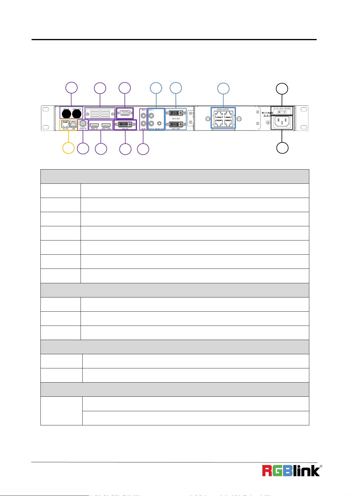
1.2.1 Rear Panel......................................................................................................................................... 8
1.2.2 Front Panel........................................................................................................................................ 9
1.2.3 Dimension........................................................................................................................................ 11
Chapter 2 Install Your Product................................................................................................................................12
2.1 Plug in Signals............................................................................................................................................12
2.2 Plug in Main Power....................................................................................................................................12
2.3 Turn on Your Product.................................................................................................................................12
Chapter 3 Use Your Product...................................................................................................................................13
3.1 Use the MENU Button...............................................................................................................................13
3.2 MENU Structure......................................................................................................................................... 13
3.3 Use the Menu............................................................................................................................................. 14
3.3.1 LED Configuration.......................................................................................................................... 14
3.3.2 Out Bright.........................................................................................................................................16
3.3.3 Input.................................................................................................................................................. 16
3.3.4 Output............................................................................................................................................... 18
3.3.5 Transition..........................................................................................................................................23
3.3.6 Audio................................................................................................................................................. 23
3.3.7 Split................................................................................................................................................... 24
3.3.8 System..............................................................................................................................................24
3.3.9 Language......................................................................................................................................... 26
3.3.10 Factory Reset................................................................................................................................26
3.4 Shortcut Buttons.........................................................................................................................................26
3.4.1【TAKE】Button.............................................................................................................................. 26
3.4.2【PIP】Button.................................................................................................................................. 27
3.4.3【SCALE】Button........................................................................................................................... 27
3.4.4【SAVE】Button.............................................................................................................................. 28
3.4.5【LOAD】Button............................................................................................................................. 28
Chapter 4 Ordering Codes...................................................................................................................................... 29
4.1 Product.........................................................................................................................................................29
4.2 Options.........................................................................................................................................................29
Chapter 5 Support .................................................................................................................................................. 30
5.1 Contact Us...................................................................................................................................................30
Chapter 6 Appendix..................................................................................................................................................31
6.1 Specification................................................................................................................................................31
6.2 Load LED Configuration File....................................................................................................................34
6.3 Terms & Definitions....................................................................................................................................41
6.4 Revision History......................................................................................................................................... 48

©Xiamen RGBlink Science & Technology Co., Ltd.
3
Thank you for choosing our product!
This User Manual is designed to show you how to use this video processor quickly and make use of all the
features. Please read all directions and instructions carefully before using this product.
Declarations
FCC/Warranty
Federal Communications Commission (FCC) Statement
This equipment has been tested and found to comply with the limits for a class A digital device, pursuant to Part
15 of the FCC rules. These limits are designed to provide reasonable protection against harmful interference
when the equipment is operated in a commercial environment. This equipment generates, uses, and can radiate
radio frequency energy and, if not installed and used in accordance with the instruction manual, may cause
harmful interference to radio communications. Operation of this equipment in a residential area may cause
harmful interference, in which case the user will be responsible for correcting any interference.
Guarantee and Compensation
RGBlink provides a guarantee relating to perfect manufacturing as part of the legally stipulated terms of
guarantee. On receipt, the purchaser must immediately inspect all delivered goods for damage incurred
during transport, as well as for material and manufacturing faults. RGBlink must be informed immediately in
writing of any complains.
The period of guarantee begins on the date of transfer of risks, in the case of special systems and software on the
date of commissioning, at latest 30 days after the transfer of risks. In the event of justified notice of compliant,
RGBlink can repair the fault or provide a replacement at its own discretion within an appropriate period. If this
measure proves to be impossible or unsuccessful, the purchaser can demand a reduction in the purchase price or
cancellation of the contract. All other claims, in particular those relating to compensation for direct or indirect
damage, and also damage attributed to the operation of software as well as to other service provided by RGBlink,
being a component of the system or independent service, will be deemed invalid provided the damage is not
proven to be attributed to the absence of properties guaranteed in writing or due to the intent or gross
negligence or part of RGBlink.
If the purchaser or a third party carries out modifications or repairs on goods delivered by RGBlink, or if the goods
are handled incorrectly, in particular if the systems are commissioned operated incorrectly or if, after the transfer
of risks, the goods are subject to influences not agreed upon in the contract, all guarantee claims of the purchaser
will be rendered invalid. Not included in the guarantee coverage are system failures which are attributed to
programs or special electronic circuitry provided by the purchaser, e.g. interfaces. Normal wear as well as normal
maintenance are not subject to the guarantee provided by RGBlink either.
The environmental conditions as well as the servicing and maintenance regulations specified in this manual must
be complied with by the customer.

©Xiamen RGBlink Science & Technology Co., Ltd.
4
Operators Safety Summary
The general safety information in this summary is for operating personnel.
Do Not Remove Covers or Panels
There are no user-serviceable parts within the unit. Removal of the top cover will expose dangerous voltages. To
avoid personal injury, do not remove the top cover. Do not operate the unit without the cover installed.
Power Source
This product is intended to operate from a power source that will not apply more than 230 volts
rms between the supply conductors or between both supply conductor and ground. A protective
ground connection by way of grounding conductor in the power cord is essential for safe operation.
Grounding the Product
This product is grounded through the grounding conductor of the power cord. To avoid electrical shock, plug the
power cord into a properly wired receptacle before connecting to the product input or output terminals. A
protective-ground connection by way of the grounding conductor in the power cord is essential for safe
operation.
Use the Proper Power Cord
Use only the power cord and connector specified for your product. Use only a power cord that is in good
condition. Refer cord and connector changes to qualified service personnel.
Use the Proper Fuse
To avoid fire hazard, use only the fuse having identical type, voltage rating, and current rating characteristics.
Refer fuse replacement to qualified service personnel.
Do Not Operate in Explosive Atmospheres
To avoid explosion, do not operate this product in an explosive atmosphere.
Installation Safety Summary
Safety Precautions
For all GX4pro processor installation procedures, please observe the following important safety and handling
rules to avoid damage to yourself and the equipment.
To protect users from electric shock, ensure that the chassis connects to earth via the ground wire provided in
the AC power Cord. The AC Socket-outlet should be installed near the equipment and be easily accessible.

©Xiamen RGBlink Science & Technology Co., Ltd.
5
Unpacking and Inspection
Before opening GX4pro processor shipping box, inspect it for damage. If you find any damage, notify the shipping
carrier immediately for all claims adjustments. As you open the box, compare its contents against the packing slip.
If you find any shortages, contact your sales representative.
Once you have removed all the components from their packaging and checked that all the listed components are
present, visually inspect the system to ensure there was no damage during shipping. If there is damage, notify
the shipping carrier immediately for all claims adjustments.
Site Preparation
The environment in which you install your VENUS X1 should be clean, properly lit, free from static, and have
adequate power, ventilation, and space for all components.

©Xiamen RGBlink Science & Technology Co., Ltd.
6
Chapter 1 Your Product
1.1 In the Box
Note:
AC Power Cable supplied as standard according to destination market.
AC Power Cord
DVI to HDMI Cord
USB Cable

©Xiamen RGBlink Science & Technology Co., Ltd.
7
1.2 Product Overview
GX4pro is an video processor which supports DVI output resolution at 2048x1152@60 and offers multiple test
pattern output resolution options. Beside standard with a 1 HDMI (with loop), 1 CVBS, 1 VGA, 1 DVI and 1 pair of
Audio analog connectors, it also comes with 1 empty module slots for any single input modules selecting from
HDMI,DP,DVI,SDI,VGA,CVBS and USB modules. Capability of support any input makes GX4pro have features of PIP
(dual pictures),synchronized video with audio control and seamless switching between different inputs. Moreover
Extended Display Identification Data(EDID management) make sure display perfectly spot to spot.
GX4pro can work as LED display controller when universal senders cards is installed. There are 2 empty slots
fitting for one 2.6mega pixels sender card or two 1.3mega pixels sender cards. RGBlink dedicated sender card
module SubitoNX™ Quatro is also an an option to control LED display. It provides 2.3 mega pixels display up to
horizontal 3840 pixels or vertical 1920 pixels, through 4 RJ45 ports.
GX4pro with SubitoNX Quatro Module
Note:GX4pro is also compatible with sender cards from Novastar,Linsn Technology,Colorlight and Mooncell.But
GX4pro only supports power supply to the sender cards from other companies and can not control them.

©Xiamen RGBlink Science & Technology Co., Ltd.
8
1.2.1 Rear Panel
INPUT CONNECTORS
1
1 specific slot for optional SDI module
2
1 slot for optional module
3
VGA input
4
CVBS Input
5
HDMI In/Loop
6
DVI input
7
Audio input
OUTPUT CONNECTORS
8
Audio Output
9
DVI Output
10
Slots preserved for sender cards
POWER
11
Power switch
12
Power IEC-3
CONTROL PORT
13
USB-A
RS232
10
9
7
5
11
3
1
8
6
4
2
13
12

©Xiamen RGBlink Science & Technology Co., Ltd.
9
1.2.2 Front Panel
OLED Display
Displays current status of the product, and for feature selections provides interactive
choices in conjunction with buttons on the front panel.
Rotary Knob
This knob used for menu selections and confirmation.
turn to left and right to select menu item and push to confirm selection.
Buttons
This button used for menu selections Push the button again will return to the last level
menu or exit the menu.
PIP/DSK Button
PIP and DSK function reuse button.
Push the button to enter to the PIP menu items.
This button used for size and position adjusting.
When input USB signal, it reused the stop and play button, push the button to stop or
play the USB video file.
Split function button.
When connect USB signal, it reused the move next button, push the button to play the
next USB video file.
Save all current settings to 1 -16 scene and Number 1.
Restores/Loads saved setting from 1-16 scene and Number 6.
HDMI input source selection and Number 2
CVBS input source selection and Number 3
VGA input source selection and Number 4.

©Xiamen RGBlink Science & Technology Co., Ltd.
10
CVBS input source selection and Number 5.
SDI input source selection and Number 7.
After optional input module is fitted, this button is to select the optional input source.
Number 8.
Short cut button of Audio Menu and Number 9
Short cut button of Black Out and Number 0.
Switch button with transition effect.

©Xiamen RGBlink Science & Technology Co., Ltd.
11
1.2.3 Dimension
Following is the dimension of GX4pro for your reference::
Dimension:480mm×303mm×45mm

©Xiamen RGBlink Science & Technology Co., Ltd.
12
INPUT HDMI:NO INPUT
SV: 2.00 SN:1043
OUTPUT FORMAT:1920×1080@60
Chapter 2 Install Your Product
2.1 Plug in Signals
Connect signals to the product (ensure all devices are powered off first). Tighten connector screws/locks where
provided.
2.2 Plug in Main Power
Connect IEC cable to device and plug into wall socket. Turn on power at wall socket.
2.3 Turn on Your Product
Turn the power switch on the rear to ON position.
TST screen shows as below,meanwhile the device enter initializing state after that,the device will load the
previously saved setting. On delivery, the default input is HDMI.

©Xiamen RGBlink Science & Technology Co., Ltd.
13
Chapter 3 Use Your Product
3.1 Use the MENU Button
Push【MENU】button to enter main menu.
Turn the knob to select corresponding menu item.
The symbol >indicate that the item is selected.
Push the knob to confirm the operation.
The symbol*means the selected item is under editing state, ready to be set or checked
The operation diagram is as follows:
3.2 MENU Structure
The MENU structure is shown in the figure below:

©Xiamen RGBlink Science & Technology Co., Ltd.
14
3.3 Use the Menu
Use the menu system for convenient and intuitive operation. GX4pro TST display shows the menu items. The TST
display will show the default state when the menu is not in use, or the operation has timed out. Using the
【MENU 】button and rotary knob in the front panel, the TST display will show the corresponding menus
according to user selections.
3.3.1 LED Configuration
Image Control One is installed with SubitoNX™Quatro Sender Module or other universal sender card.
Here is the led configuration sub-menu.
1. QUICK CONNECT
1.1 SEND CARD SET
CHOOSE CABLE:choose the output LAN port on the Sender,there are 4 ports available.
X,Y : the horizontal and vertical position of the display that the Sender card control the on LED screen.
One port of SubitoNX Sender can control 650K pixels. If a LED screen is under 650K pixels.
X,Y can be 0.
X maximum 1920
Y maximum 1080
SAVE SENDER CARD: save the X,Y setting to sender card.
RESET SEND CARD: reset sender card if parameters set above is not proper.
>QUICK CONNECT >>
ADVANCED >>
CONFIG FILE >>
>SEND CARD SET >>
RECEIVE CARD SET >>
RESET ALL CARD
>CHOOSE CABLE 1
X 0
Y 0
WIDTH 0
HEIGHT 0
SAVE SENDER CARD
RESET SENDCARD

©Xiamen RGBlink Science & Technology Co., Ltd.
15
CONNECT TYPE
SAVE TO RECEIVER CARD
1.2 RECEIVE CARD SET
CHOOSE CABLE:choose the output LAN port on the Sender. There are 4 ports available.
HORIZONTAL CARD: how many receive cards needed to receive the data that the chosen sender port offer.
WIDTH: width of each led cabinet
HEIGHT:height of each led cabinet
HOR OFFSET: horizontal offset, -1-4095
VER OFFSET: vertical offset,-1-4095
CONNECT TYPE: the connection type of led cabinet.
There are 8 types available .
SAVE RECEIVER CARD: save setting above to receiver card.
1.3 RESET ALL CARD: reset all sender card and receiver card.
2. ADVANCED
2.1 COLOR TEMP
RED,GREEN,BLUE: value range from 0 to 255
SAVE TO SENDER CARD: save above setting to sender card
>CHOOSE CABLE 1
HORIZONTAL CARD 1
VERTICAL CARD 3
WIDTH 128
HEIGHT 192
>HOR OFFSET 0
VER OFFSET 0
CONNECT TYPE >>
>COLOR TEMP >>
>RED 255
GREEN 255
BLUE 255
SAVE TO SEND CARD

©Xiamen RGBlink Science & Technology Co., Ltd.
16
INPUT INFO >>
SIZING ADJUST >>
USB CONTROL >>
VGA ADJUST >>
DVI4 In1 NO EXT
3. CONFIG FILE
Users can load LED configuration files from LED manufacturers to the Image Control One devices by XTOOL. There
are 15 manufacturers items in the sub-menu and each manufacture can store 16 files. 270 files in total allow to
be loaded.
3.3.2 Out Bright
Output brightness to adjust the brightness of LED screen, value ranging from 0-255
3.3.3 Input
1. INPUT INFO
Show the current input format and resolution
2. SIZING ADJUST
PREINSTALL FILE >>
ADC AJUST >>
SDI ADJUST >>
EDID MANAGE >>
VGA TYPE VGA
H SIZE 1024
V SIZE 768
H POS 0
V POS 0
RESET SIZE
MASK TOP >>
MASK BOTTOM >>
MASK LEFT >>

©Xiamen RGBlink Science & Technology Co., Ltd.
17
H POS 0
V POS 0
CLOCK 0
PHASE 0
>AUTO ADJUST
>AUTO ADJUST
H SIZE:set the horizontal pixels of input image to zoom or scale the input signal
V SIZE:Set the vertical pixels of input image to zoom or scale the input signal
H POS:set the horizontal position of image
V POS:set the horizontal position of image
RESET SIZE:if the size is not proper, turn knob to RESET SIZE and press knob
MASK TOP:crop the top of image
MASK BOTTOM:crop the bottom of image
MASK LEFT:crop the left part of image
MASK RIGHT:crop the right part of image
RESET MASK:If the crop not proper, turn knob to RESET MASK and press knob.
3. VGA ADJUST
Non-standard VGA input signal can cause the input image shifting or not in full screen, therefore, users need to
adjust VGA input as follows:
After selecting <AUTO AJUST> the device will automatically adjust the H POS,V POS, CLOCK and PHASE to make
input image no shifting and full screen.
Note:If one <AUTO AJUST> cannot meet the needs, users can do <AUTO AJUST> many times. The system can
automatically save the ADJUST parameter. Users can also go to <AUTO AJUST> by pressing 【VGA】
button for 10s.
4. ADC ADJUST
AUTO ADUST: YES <OK>,NO <MENU>
RESET: YES <OK>,NO <MENU>
>AUTO ADJUST >>
RESET >>
MASK RIGHT >>
RESET MASK

©Xiamen RGBlink Science & Technology Co., Ltd.
18
H POS 127
V POS 127
ANTI ALIAS STEP_0
RESET
5. SDI ADJUT
Image Control One with SDI optional module come with SDI ADJUST in the menu.
6. EDID MANAGE
DESTINATION: DVI or HDMI
SOURCE: RGB DVI, RGB HDMI, FOLLOW, CUSTOM
CUSTOM EDID
Customize resolution for EDID
7. VGA TYPE
Choose signal type for VGA button. VGA or YPbPr.
8. DVI( 4 In 1)
Image Control One with optional DVI module installed comes with such signal types as VGA, DVI, CVBS, YPbPr. It is
offered to users to choose the signal type through the DVI connector which is compatible with VGA, DVI, CVBS,
YPbPr via adapter.
3.3.4 Output
OUTPUT INFO >>
OUTPUT FORMAT >>
OUTPUT ADJUST >>
SCREEN >>
RATIO NORMAL
PICTURE >>
TEXT OVERLAY >>
DISPLAY MODE >>
DESTINATION HDMI
SOURCE RGB DVI
CUSTOMIZE:
>1920x1080@60
GAMMA LINEAR

©Xiamen RGBlink Science & Technology Co., Ltd.
19
1. OUTPUT INFO
show current input information
2. OUTPUT FORMAT
STANDARD: standard output resolution, 26 types available to choose from 720x480i@60 to 2560x816@60
CUSTOMIZE: custom resolution
Turn the knob to resolution line and press the knob “>” (arrow )change to “*” (star ) put in the numbers for
width, then press the knob to confirm the number.
Put in the numbers for height and frame rate in the same way.
Note: The number buttons lighting up indicate that users can use button to key in numbers.
3. OUTPUT ADJUST
DVI MODE: DIV or HDMI
BITS: DVI 8bit ,HDMI 8/10/12 bit
COLOR SPACE: IMAGE or VIDEO
>1920x1080@60
DVI MODE DVI
BITS 8 BIT
COLOR SPACE IMAGE
DE OFF
DE H POS 185
DE V POS 41
DE H SIZE 1920
DE V SIZE 1080
H POLARIRY POS
V POLARITY POS
>STANDARD >>
CUSTOMIZE >>
CUSTOMIZE:
>1920x1080@60
DVI MODE DVI
BITS 8 BIT
COLOR SPACE IMAGE
DE ADJUST >>

©Xiamen RGBlink Science & Technology Co., Ltd.
20
>DE OFF
H POS 185
V POS 41
H SIZE 1920
DE ADJUST
DE: ON or OFF
H POS: horizontal position, value from 0 to 1920
V POS: vertical position, value form 0 to 1080
H POLARITY:horizontal polarity, POS (positive) or NEG (negative)
V POLARITY:vertical polarity,
POS (positive) or NEG (negative)
RESET: reset above setting if not proper
4. SCREEN
The setting of <SCREEN> is based on the resolution of the LED screen,applicable under single picture mode. For
example to display picture on a LED screen with resolution 1408x832, first of all, a resolution close to or bigger
than 1408x832 shall be selected. In this case, 1440x900 or resolution above will be proper choice. The closer to
the LED screen resolution, the better the display will be.
H SIZE:horizontal pixels, turn the knob or use the digital button to input 1408.
V SIZE:vertical pixels, turn the knob or use the digital button to input 832.
H POS:horizontal position, default 0, set the value as the way of H SIZE and V SIZE.
V POS:vertical position, default 0, set the value as the way of H SIZE and V SIZE.
MODE-- Mode option, select SCREEN SIZE.
RESET:If image quality distorts by improper operation, it can be recover by reset.
V SIZE 1080
H POLARITY POS
V POLARITY POS
MODE FULL SIZE
RESET
H POS 185
V POS 41
H SIZE 1920
V SIZE 1080
Table of contents
Other RGBlink Media Converter manuals

RGBlink
RGBlink MSP 221 User manual

RGBlink
RGBlink FLEX 8 User manual

RGBlink
RGBlink VENUS X3 User manual

RGBlink
RGBlink MSP 210C User manual

RGBlink
RGBlink VSP 516 Series User manual

RGBlink
RGBlink MSP 210V User manual

RGBlink
RGBlink VENUS X3 User manual

RGBlink
RGBlink Q16 User manual

RGBlink
RGBlink MVP 8043 User manual

RGBlink
RGBlink Q16pro-2 User manual

RGBlink
RGBlink D6 User manual

RGBlink
RGBlink FLEXpro 8 User manual

RGBlink
RGBlink VSP 628PRO User manual

RGBlink
RGBlink M1 User manual

RGBlink
RGBlink DXP D0808 User manual

RGBlink
RGBlink MSP 316H User manual

RGBlink
RGBlink MSP 312 User manual

RGBlink
RGBlink VSP 268 User manual

RGBlink
RGBlink D4 User manual

RGBlink
RGBlink VSP 628 User manual