Rhin-O-Tuff OD4012 User manual

Instruction Book
for the OD4012,
OD4000 and OD4800

OD4012, OD4000 and OD4800
Setup & Operator Manual
Issue 3 June 09
Performance Design LLC.
These punches have been designed to punch most any job that may
pass through your office. No matter what type of binding you need to
carry out, these punches can handle the job. The maximum single
punching length for the OD4012, OD4000 and OD4800 is a 11” (297mm)
format. The OD4012 and the OD4000 are electrically operated punches
and the OD4800 is manually operated. All three machines utilize a
simple two knob die lock system to retain the die punch assemblies.
2
OD4012
OD4000 OD4800

OD4012 Contents S/N:____________
___Punch (1) ___Instruction Book (1)
___Oil (1) ___Brush (1)
___Foot Pedal (1) ___Power Cord (1)
___Reversing Tool (1)
Inspected by: __________________
OD4800 Contents S/N:____________
___Punch (1) ___Instruction Book (1)
___Knob Kit (1) ___Handle with bolt (1)
a) ¼-20x1½”Knob (2) ___Oil (1)
___Brush (1)
Inspected by: __________________
OD4000 Contents S/N:____________
___Punch (1) ___Instruction Book (1)
___Knob Kit (1) ___Oil (1)
a) ¼-20x1½”Knob (2) ___Brush (1)
___Foot Pedal (1) ___Power Cord (1)
Inspected by: __________________


Table of Contents
Topic: Page Number:
3
Safety Alert Symbols
Safe operating guidelines
Proper machine placement
Attach OD4800 Handle
Providing electric power
Die installation / Maintenance
Setting the paper stop/guide
Punching paper
Removing paper waste
Paper jam
Troubleshooting
4
4
5
6
7
7-9
10
10
10
11-12
13
Safety Alert Symbols
uThe OD4012 and OD4000 need to be plugged into a wall outlet that
provides a 15-amp, 120 volt service (16-amp, 220 volt for European
installations) and is protected by a fuse or circuit breaker at the main
electrical panel.
uIf machine cycles on its own, turn off power switch, unplug machine
from the wall outlet and call your dealer immediately for service.
uMake sure you read this section very carefully! Learn to recognize
these The OD4012, OD4000 and OD4800
have been designed to provide a high level of protection to an
operator. Follow the guidelines below while installing, operating and
maintaining your machine.
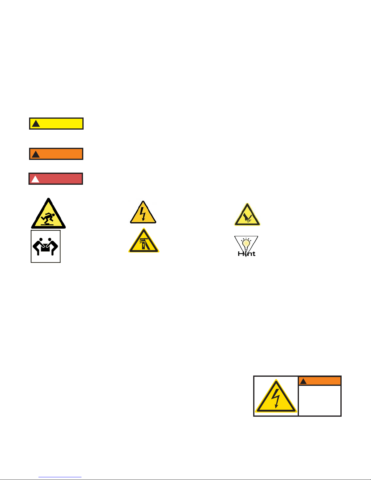
Safety Alert Symbols.
4
!DANGER
!WARNING
Safe Operating Guidelines
!CAUTION CAUTION: Indicates a hazardous situation which, if not avoided, could result in
minor or moderate injury. It may also be used without the safety alert symbol as
an alternative to "Notice".
WARNING: Indicates a hazardous situation which, if not avoided, could result in
death or serious injury.
DANGER: Indicates a hazardous situation which, if not avoided, will result in
death or serious injury. This signal word is to be limited to the most extreme
situations.
Trip Hazard
Two Person LIft
Electric Shock
Crushing Hazard
uAlways replace any fuse with the same type and
amperage fuse as indicated on the machine.
Hazardous voltage
inside.
Disconnect power
before servicing.
!WARNING
Cutting Hazard
Hint or Suggestion
uAlways keep this instruction manual with the machine for reference to
safe operating guidelines and correct operation of the machine.
5
Placing your machine in the proper location:
uBefore lifting machine, turn power off and
remove the power cord from the wall outlet.
The machine is very heavy! Never attempt to lift
the machine by yourself. Two people will be
needed to lift the machine.
uPlace the machine on a hard level surface, place the foot pedal on the
floor in front of the machine. Ensure the placement of machine allows
for ergonomic work flow (separate locations for un-punched books and
punched books).
u
u
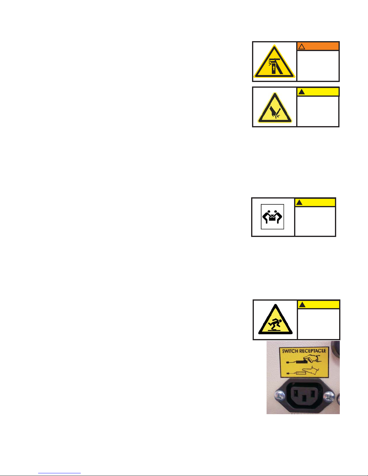
Connect the foot-pedal into the foot-pedal
receptacle on the back of the machine, do not
attempt to connect foot-pedal into anything other
than the foot-pedal receptacle.
paper activated switches are available
for these punches. These switches replace the foot-pedal and plug
into the foot-pedal receptacle on the back of the machine.
Optional
Lifting Hazard
Single person
lift could result
in injury.
Two person lift required.
!CAUTION
uTurn power switch off before maintaining or
changing die assembly.
!WARNING
Crush hazard.
Keep hands away
from moving parts.
Lockout and disconnect
power before servicing.
!CAUTION
Cutting Hazard
Injury to fingers
and hands.
Use hand protection
uUse of appropriate hand protection should be
utilized to avoid injury from handling of materials.
uFollow all recommended workplace procedures for repetitive activities.
!CAUTION
Tripping Hazard
Bodily injury could
occur from fall.
Route cables away
from walkways
6
Attach Handle to OD4800:
uThe OD4800 manual punch is shipped with the handle removed from
the punch. You will need two 3/8” wrenches (not supplied) to tighten
the handle bolt.
Diagram 1 (Image of OD4800)
?
?
?
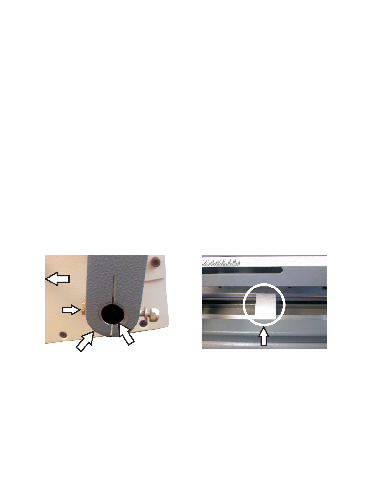
Locate the handle and remove the nut, washer and bolt from the
handle.
Orientate the handle so the black handle grip extends to the right of
the machine as seen on front cover of this book.
Slide handle onto exposed crankshaft of machine and align the holes
in the handle with the hole in the crankshaft.
Insert the bolt completely through the handle and install the washer
and nylock nut. See photo below left.
Tighten the nut securely so there is not play between the handle and
the crankshaft.
Open the top grey lid of the punch and remove the styrofoam block.
See photo below right.
Remove Styrofoam
Handle Crankshaft
Front of
Machine
Bolt

7
Providing power to the machine:
uPower cord shall be certified for the country
where the machine will be installed. Plug one
end of the power cord into the power cord
receptacle on the back of the machine. The
other end goes into the wall outlet.
Die Installation:
u
u
u
u
u
OD4012 Make sure the machine
is turned off before installing the die
Diagram 2.
.
Make sure there is no paper dust or paper chips
in the machine die slot before installing the die.
Install the die by sliding it into the opening
located on the left hand side of the machine. Make sure the punch pin
retainer slides into the slot on the backside of the opening.
Install die until right side of die is flush to exterior of right side of
machine.
Thread both retained die lock knobs into the die and tighten evenly
until the die can not move.
Diagram 2. (Image of OD4012)
!DANGER
Hazardous voltage.
Use only approved
power cord
assemblies.
!WARNING
Crush hazard.
Keep hands away
from moving parts.
Lockout and disconnect
power before servicing.
Die Lock Knob
Punch Pin
Retainer

8
u
u
u
u
u
Install the die by sliding it into the opening of the machine located on
the left hand side of the machine. Make sure the punch pin retainer
slides into the slot of the pusher bar.
Thread both die lock knobs into die
assembly and tighten evenly until die assembly can not move.
OD4000/OD4800: Diagram 3.
Make sure there is no paper dust or paper chips
in the machine die slot before installing the die.
Install die until right side of die is flush to exterior of right side of
machine.
Locate the two supplied die lock knobs and insert them into the left
and right sides of the machine.
Make sure the
machine is turned off before installing the
die.
Diagram 3. (Image of OD4000)
Comb Die Backspace (Margin) Adjustment
uThe comb die assemblies for the OD4012, OD4000, and OD4800
have a four position adjustable backspace. The positions are changed
by pulling the adjustor bar to the left for deeper settings (commonly
used for average to thicker sized books) and pushing the adjustor bar
to the right for shallower settings (commonly used for thinner sized
books).
!WARNING
Crush hazard.
Keep hands away
from moving parts.
Lockout and disconnect
power before servicing.
Die Lock Knob
Punch Pin
Retainer
Other manuals for OD4012
1
This manual suits for next models
2
Table of contents
Other Rhin-O-Tuff Binding Machine manuals

Rhin-O-Tuff
Rhin-O-Tuff 3000 Manual instruction

Rhin-O-Tuff
Rhin-O-Tuff HD8000 User manual

Rhin-O-Tuff
Rhin-O-Tuff Pro Series 3250CL Technical Document

Rhin-O-Tuff
Rhin-O-Tuff Onyx PAL-14 Piks-A-Lift User manual

Rhin-O-Tuff
Rhin-O-Tuff HD6500 User manual

Rhin-O-Tuff
Rhin-O-Tuff APES-14-77 Installation guide

Rhin-O-Tuff
Rhin-O-Tuff OD4000 User manual

Rhin-O-Tuff
Rhin-O-Tuff Econ-O-Roll HD-e4100 User manual

Rhin-O-Tuff
Rhin-O-Tuff HD 7000 User manual

Rhin-O-Tuff
Rhin-O-Tuff ONYX 5000 Pro User manual


