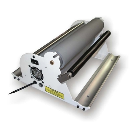
Rhin-O-Tuff Onyx PAL-14 Piks-A-Lift User manual

Issue “0” Part #900770 www.RHIN-O-TUFF.com
PAL-14
Piks-A-Lift
Operator’s Training
Manual
Issue “0” 03/05
PDI Part # 900770
Performance Design Inc.
2350 East Braniff St.
Boise Idaho 83716

Issue “0” Part #900770 www.RHIN-O-TUFF.com
This manual contains very important safety information
and must be read!
PAL-14 Operator’s Training Manual
Issue “0” 01/05
The PAL-14 paper separator will greatly increase productivity. An in-depth look at
set up procedures is necessary to achieve maximum results.
The PAL-14 can attach to the OD-4000, OD-4012, OD-4800, HD-6500, HD-7000,
or HD-7700 Performance Design Inc. punches and can also stand alone. The
PAL-14 can also directly mount on top of Performance Design’s APES-14 and
APES-14-77. Paper sizes range from 5-1/2” x 5-1/2” (140mm) through 14” x 14”
(356mm). A maximum of 6” (152mm) can be stacked at a time. This manual
discusses all of the necessary steps to use and care for your machine.

Issue “0” Part #900770 www.RHIN-O-TUFF.com
Table of Contents
Chapter: Page Number:
1) Important safety notice! 4
2) Shipment Overview of the PAL-14 5
3) Assembly of PAL-14 6
4) Placing the PAL-14 in the proper location & Binding Styles 7
5) Mounting the PAL-14 onto the HD-6500, HD-7000 or HD-7700 7
6) Mounting the PAL-14 onto the OD-4012, OD-4000 or OD-4800 8
7) Mounting the PAL-14 onto an APES-14 9
8) Use as stand alone 10
9) Overview of your PAL-14 paper separator 10
¾PowerSwitch.
¾Green Start Button.
¾Paper Amount, Adjustment Knob.
¾Book Stop Plate.
¾Tall Clamp Rod.
¾Left Book Stop assembly
¾Plunger Bracket
¾Sensor and Stabber
¾Reflector
¾Straight Edge Stop
¾Fuse Holder.
10)Detailed Use of the PAL-14 11
¾Powering up the PAL-14
¾Green Start Button
¾Book Stop Plate Adjustment Procedure.
¾Left Book Stop Rod Adjustment Procedure
¾Plunger Bracket 12
¾Loading Paper
¾Paper Amount Adjustment Knob 13
11)Paper Separating and Punching. 13
12)Quick Setup Guide 14
13)Trouble Shooting 15
14)Schematics 16
15)Product Registration and Contact Information 17

Issue “0” Part #900770 www.RHIN-O-TUFF.com
Important Safety Notice!
Make sure you read this section very carefully! Learn to recognize this Safety
Alert Symbol. The PAL-14 has been designed to provide a very high
level of protection to an operator. Follow the guidelines below while
installing, operating and maintaining your machine. Read this manual
and keep for future use.
¾Always replace fuses with the correct amperage and type:
9115VAC model use:
2ea. #007120 FUSE, 2 AMP MDL SLO 1/4 X 1 1/4
1ea. #001659 FUSE,1.5 AMP GMA M5 X 20MM (circuit board)
9230VAC model use:
2ea. #007019 FUSE, 1 AMP GDC SLOW M5 X 20
1ea. #001659 FUSE,1.5 AMP GMA M5 X 20MM (circuit board)
Refer to the serial number label on the rear of the machine to
determine the voltage of your machine.
Serial Number Label Example.
¾If the machine runs erratically while the machine is on, unplug
the PAL-14 and call your dealer immediately for service.
¾Never attempt to service your machine unless you are a
qualified Technician. There are no user serviceable parts inside
the PAL-14. NEVER REMOVE BACK COVER! Doing so may
result in personal injury!
¾Never operate the PAL-14 if the provided power cord does not
fit your outlet. Power cord shall be certified for the country
where the machine will be installed.

5
Shipment Overview of the PAL-14;
The very first step is to un-box the PAL-14 including the smaller accessory kit
inside. Your PAL-14 requires some assembly before it can operate. Find an open
area and layout the components inside the boxes as shown in illustration 2.0;
Listed below are the items in illustration 2.0. Please refer back to this list when
the manual describes their use.
1) Knob, screw, washer, and spacer kit.
2) APES Module standoff kit.
3) Book Stop Plate, remove from standoffs on PAL-14 subassembly.
4) Left Book Stop assembly.
5) Tall Clamp Rod.
6) Warranty Registration Card, Please fill this out immediately and mail in.
7) Main PAL-14 subassembly.
8) Information sheet for PAL-14 stand-alone assembly.
9) Power Cord (Boxed separately in Europe).
10) Mate Blocks, used in mounting with HD-7000 and HD-7700 punches.
11) OD Bracket Kit, used in mounting with OD-4012, OD-4000, and OD-4800
punches.
12) Plunger Bracket.
13) PAL-14 Table.
Some of these items will not be required depending on your mounting style. Later
in the manual we will describe the many mounting options for your PAL-14
including using the stand-alone option. When you have chosen your mounting
option store the extra components for future use.

6
Assembly of PAL-14: See illustration 3.0
Some assembly is required before using the PAL-14.
9Locate the PAL-14 table (1), table attachment screws (2) and Allen key
(3). Using the screws provided, attach the table to the main machine
assembly (4) as shown.
9Attach the left book stop assembly (5) using the three winged knob (6).
This can be installed at several different locations depending on the length
of the book. This will be covered later in this manual.
9Attach the Book Stop Plate (7) on the two dowel studs with the short
flange (8) facing toward the rear of the machine. The Book Stop has two
possible locations, use the forward position for now, use of locations will
be covered later in the manual. Use the Tall Clamp Knob (9) to secure
plate in place as shown.
9Attach the plunger bracket (10) to the book stop plate (7). The location of
this is not important at the moment. This will be covered later in this
manual.

7
Placing the PAL-14 in the proper location & Binding Styles;
Locate a clear work area with an outlet within 5 feet that provides a 15-amp
service (16-amp European) which is protected at the customer’s circuit box. The
work area must be a solid, firm cabinet or a heavy duty table with a flat level
surface. Power cord shall be certified for the country where the machine will
be installed.
Placing your PAL-14 in the proper location will also depend on your punching
technique. If you like to stand while punching, mount the PAL-14 on top of your
punch machine or Performance Design’s APES-14 or APES-14-77. If you want to
punch paper while seated, and the PAL-14 is attached to the APES-14, you may
notice an inconvenience while trying to pick paper and load it into the APES–14
paper slot while the previous loaded paper is exiting. It may be best to use the
PAL-14 as a stand alone unit. The best location when using the PAL-14 in this
mode would be to the right of the APES-14 and punch. The next chapters will
cover all the optional mountings. Review all of them, pick and follow one then
continue to Chapter 9; Overview of the PAL-14 Paper Separator.
Mounting the PAL-14 onto the HD-6500, HD-7000 or HD-7700;
Locate the Mate Blocks, 1 ¼” long ¼”-20 socket head
screws, and Allen wrenches provided inside the
shipping kit as shown to the right.
These will be required in the next step.
ALWAYS USE TWO PEOPLE TO MOVE
AN ELECTRIC PUNCH!
HD-6500 and HD-7000 Instructions;
See Illustration 5.1 on next page.
Locate the two top-most and rear-most
screws on the side of your HD-
6500/7000. Inserting the short end of
the Allen wrench into the screw head,
remove the two screws.
HD-7700 Instructions;
See Illustration 5.2 on next page.
Locate the two top-most and forward-
most screws on the side of your HD-
7700. Inserting the short end of the
Allen wrench into the screw head,
remove the two screws.
Both HD-6500/7000 and HD-7700 Instructions cont...
Store the two screws removed from the punch. Locate one of the
Interface Blocks and orient it against the two now-available holes.
Orient the block so that the interface block oval hole (1) is forward
and the counter bores face out. To the right is an example of a
counter bore. Use the 1 ¼” long ¼”-20 socket head screws provided to secure
the block to the machine with the short end of the Allen wrench. Tighten the rear
screw first then the forward screw. Repeat this step on the other side of your
punch with the other block.

8
Place your PAL-14 on top of your punch, as shown in illustration 5.3. Use a white
spacers (1) under the forward sheet metal portion of the table as shown, then
use the 3-winged knobs to fasten the PAL-14 to your punch as shown. Repeat on
opposite side of your PAL-14. Only three knobs are actually required, the knob
that is located on the machine forward and right may be removed if there is
interference with the paper stack.
Mounting the PAL-14 onto the OD-4000, OD-4012 or OD-4800:
See illustration 6.0.
Locate the OD hardware kit included with the PAL-14. The kit includes the
following parts; Two OD brackets (1) (left hand & right hand), four mounting
screws, and an Allen wrench. Attach the brackets as shown using the screws
and wrench, place your PAL-14 on top of the OD punch and secure with the two
3-winged knobs. The (OD-4800 users: Most likely you will never find a need for
mounting the PAL-14 on an OD-4800 but it is possible. Call the factory at 1-800
390-5782, ask for technical support, and make sure you have the most recent
model punch or a shaft extension upgrade will be required for the OD-4800).

9
Mounting the PAL-14 onto an APES-14:
See illustration 7.0.
Make sure the APES is mounted on the HD punch before proceeding with this
step, refer to the APES manual.
Locate the APES module standoff kit. Remove the four long metal spacers (1)
and find the two short plastic spacers (2). The position of these standoffs will be
determined by the slots located on the APES base plate. There is no exact
location for these standoffs or which slots are used. Use the 3-winged knobs (3)
to secure the PAL-14 to the APES. The operator can choose a comfortable
working distance for the PAL-14 by choosing different mounting positions. The
long spacers will be used toward the rear of the PAL-14 base plate. There is a
threaded shaft protruding from one end of the long spacer. Insert this threaded
shaft through the slot of the APES, and screw it into the interface blocks
previously mounted on the HD punch. Use the same procedure for the front two
spacers except this time, insert the threaded shaft through the plastic washer
first, and then through the slots of the PAL-14. Only three knobs are actually
required, the knob that is located on the machine forward and right may be
removed if there is interference with the paper stack.

10
Use as stand alone:
Locate the Information sheet for PAL-14 stand-alone assembly. Follow the
instructions.
Overview of the PAL-14 Paper Separator:
See illustration 9.0.
The PAL-14 has many useful features to increase your punching productivity.
1. Power Switch: This switch turns on the main power to the PAL-14. In
case of any emergency use the power cord as the main power cutoff!
2. Green Button: Press this button to start the picking process. It is also
used to reset the stabber to the pile more quickly so you do not have to
wait for it to travel to its top position.
3. Paper Amount Adjustment Knob: Use this knob to adjust the number of
sheets to be separated. This adjustment should be determined by the type
of die being used and the type of machine.
4. Book Stop Plate: The Book Stop plate will need to be adjusted when
changing a job from tabs to straight edge binding or vice versa.
5. Tall Clamp Knob: Allows 2-position movement of the Book Stop Plate.
6. Left Book Stop assembly: The Book Stop Rod acts as a left hand book
stop for different length paper.
7. Plunger Bracket: The plunger will prevent the sheets being lifted from
moving forward. Only use the plunger rod if the paper is being pushed
forward as the stabber is entering the pile of paper.
8. Sensor and Stabber: Detects and picks paper. Never adjust sensor!
9. Reflector: Works with the sensor to detect paper.
10.Straight Edge Stop: Assists in aligning non-tabbed paper.
11.Fuse Holder: Not Shown, located on the rear of machine. Always replace
fuses with the correct amperage and type.

11
9115VAC use:
2ea. #007120 FUSE, 2 AMP MDL SLO 1/4 X 1 1/4
1ea. #001659 FUSE,1.5 AMP GMA M5 X 20MM (circuit board)
9230VAC use:
2ea. #007019 FUSE, 1 AMP GDC SLOW M5 X 20
1ea. #001659 FUSE,1.5 AMP GMA M5 X 20MM (circuit board)
Detailed Use of the PAL-14 Paper Separator:
See illustration 9.0 on previous page.
1. Powering up the PAL-14:
Make sure the PAL-14 is plugged into a wall outlet. Press the main switch to
turn the machine on. The stabber assembly may move to its uppermost
position if not already there.
2. Green Start Button:
Press this button to start the picking process. It is also used to reset the
stabber to the pile more quickly so you do not have to wait for it to travel to its
top position. You can push this button anytime the paper stabber needs to be
reset. The Stabber will reset to the back position after several minutes. If
no paper is removed when this happens you will need to push the green
reset button again.
3. Book Stop Plate Adjustment Procedure:
There are two possible adjustment positions for this plate. All the way toward
the back of the machine which is for tabs and all the way forward for straight
edge books. Books with Tabs
If the rear book stop plate is in the forward position, loosen the tall clamp
knob located behind the plate. You do not have to unscrew the tall clamp
knob completely but just enough to lift the plate and move it to its back
position. There are two sets of alignment holes. Use the holes closest to
the front of the plate for tabs and the back set of holes for straight edged
books.
Books without Tabs
If the rear book stop plate is in the back position, loosen the tall clamp
knob located behind the plate. You do not have to unscrew tall clamp knob
completely but just enough to lift the plate and move it to its forward
position. There are two sets of alignment holes. Use the holes closest to
the front of the plate for tabs and the back set of holes for straight edged
books.
4. Left Book Stop Rod Adjustment Procedure: See illustration 10.0.
The left book stop rod is used to position the pile laterally so the stabber
enters the pile of paper in the proper location. Use the reference labels
located next to the stabber for the proper location of the pile, Use the right
position for straight edged books and the left position for book with tabs. Tabs

12
must have a 1/2” (12.5mm) indent so stabber enters pile correctly. Be careful
not to allow the left stop rod (1) to block sensor beam (2).
5. Plunger Bracket: See illustration 10.1.
The plunger is used to add weight to the top of the pile. The only time it will be
necessary to use this is when a lift of paper slides forward as the stabber
enters the pile. Occasionally a lift of paper will slide forward as it enters the
pile even with the plunger on the paper. This usually happens when heavy
cover stock is being separated. This is normal. The lift that pushed forward of
the pile will be equal to the amount which would have been lifted. Insert this
into the punch or APES as you would normally do. Be careful not to allow
plunger (1) to block sensor beam (2), the machine will not pick paper.
6. Loading Paper:
Load up to 6” of paper with the top of the book facing the rear of the machine. If tabs
are being separated, jog the book on the binding edge and place the tabs against the
book stop plate. Try not to let the stack of paper and tabs become misaligned as you
place the stack in position.

13
7. Paper Amount Adjustment Knob:
Set the adjustment knob clockwise to increase the number of sheets and
counterclockwise to decrease the number of sheets. Depending on the model
punch and type of die being used, this amount will vary. Use a comfortable
setting so the sheets fit into the die without much effort. The Green area is the
normal setting for narrow mouth dies, the yellow indicated the wider mouth
dies such as 3-Hole, VELOTM GBC, and Comb. The PAL-14 is not a paper
counter. The amount of paper can vary a small amount. This is usually do to
the paper relaxing which causes the pile to grow in height or the pile
compressing as the stabber enters which causes the pile to shrink. Normally,
it will vary only by a few sheets so unless you have the amount setting to
high, the paper will enter the die with no problem.
Paper Separating and Punching:
The PAL-14 has been designed to save time by always having a predetermined
amount of paper lifted from the pile, and ready for an operator to insert either into
a paper punch or the APES-14 attachment. Set the paper adjustment knob so
the stabber lifts an amount of paper which comfortably fits into the die slot. The
machine and type of die being used will determine how much paper can be
picked. The label should only be used as a reference.

14
PAL-14 Quick Setup Guide:
Books with Tabs
1. If the rear book stop plate is in the forward position, loosen the tall knob
located behind the plate. You do not have to unscrew this knob completely
but just enough to lift the plate and move it to its back position. There are
two sets of alignment holes. Use the holes closest to the front of the plate
for tabs and the back set of holes for straight edged books.
2. Load a stack of books, 6” max (152mm), against the rear book stop plate
with the tabs facing the back of the machine. The opposite end of the
binding edge is loaded against plate. Refer to the label with the picture of
the tab (TAB). Line the right side of the book with the line on the label.
Tabs must have ½” (12.5mm) indent for stabber clearance.
3. Loosen the three winged knob and set the left book stop rod to the center
of the left side of the pile.
4. Loosen the knob on the plunger bracket and move the plunger assembly
approximately five inches from the stabber. Be careful not to allow the
left stop rod to block sensor beam.
5. Turn on main power switch. Push and release the green button. The
stabber will start to descend and look for the edge of the pile. Wait for the
stabber to lift a set of sheets.
6. Remove the sheets with your index finger and thumb and insert into the
APES or paper punch. See separate instructions for APES or paper
punch.
Books without Tabs
1. If the rear book stop plate is in the back position, loosen the tall knob
located behind the plate. You do not have to unscrew this knob completely
but just enough to lift the guide and move it to its forward position. There
are two sets of alignment holes. Use the holes closest to the front of the
plate for tabs and the back set of holes for straight edged books.
2. Load a stack of books, 6” max (152mm), against the rear book stop plate.
The opposite end of binding edge is loaded against plate. Refer to the
label with the picture of the straight edge book (NO TAB). Line the right
side of the book with the line on the label. Continue following above steps
3 through 6.

15
Trouble Shooting;
Only qualified personnel should attempt to work on this
equipment!
Most of the problems you may encounter are due to setup problems. There are
two fuses on the 115VAC machine and two fuses on the 230VAC machine
located on the rear of the PAL-14 that can be replaced by the customer. Below is
a troubleshooting guide to help you through most of the problems that may be
encountered. Trouble Shooting
Symptom Possible Cause Action
Stabber assembly does
not move up or down
when green button is
pushed. (Main power
switch lamp not
illuminated)
1) Machine is off. Switch
is in down position with
light off.
2) Machine is not
plugged in.
3) Blown fuse.
1) Place switch in up
position with light
illuminated.
2) Check both ends of
the power cord.
3) Check fuse. See
Chapter 1 for fuse listing.
Stabber goes to very top
and stays after a reset. 1) Plunger is mounted to
far right.
2) Left book stop is
positioned between
sensor and reflector.
1) Re-adjust plunger to
the left.
2) Re-adjust left book
stop to the left.
Stabber moves back and
is not picking paper. 1) Stabber timed-out after
a few minutes. 1) This is normal. Push
the reset button to
continue job.
Stabber stays pushed out
or is jammed inward. 1) Stabber may have
been bumped. 1) If this continues
contact your dealer
immediately.

16
Schematics;

17
Product Registration and Contact Information;
Product registration is important to establish trouble free warranty repair of
any of your Rhin-O-Tuff equipment. Please fill out and mail in the card provided
with your machine or register on-line at www.RHIN-O-TUFF.com then select
Warranty.
For repair, service, supplies, or any other help, contact your dealer.
Table of contents
Other Rhin-O-Tuff Binding Machine manuals

Rhin-O-Tuff
Rhin-O-Tuff 3000 Manual instruction

Rhin-O-Tuff
Rhin-O-Tuff OD4000 User manual

Rhin-O-Tuff
Rhin-O-Tuff HD8000 User manual

Rhin-O-Tuff
Rhin-O-Tuff EWC-8370 User manual

Rhin-O-Tuff
Rhin-O-Tuff HC8000 User manual

Rhin-O-Tuff
Rhin-O-Tuff Pro Series 3250CL Technical Document

Rhin-O-Tuff
Rhin-O-Tuff APES-14 HD-6500 User manual

Rhin-O-Tuff
Rhin-O-Tuff APES-14-77 Installation guide

Rhin-O-Tuff
Rhin-O-Tuff KF-50 User manual

Rhin-O-Tuff
Rhin-O-Tuff HD7700 User manual