Technical Bulletin PAGE: 1/1
Model: SP3 Date: 31-Oct-97 No: 4
Subject: Controller Board ROM Modification Prepared by: A.Tokoyama
From: QAC Field Information Dept.
Classification: Troubleshooting
Mechanical
Paper path
Part information
Electrical
Transmit/receive
Action required
Service manual revision
Retrofit information
Other ( )
This bulletin describes the software modifications for the printer controller board.
The new software version has been included in the controller board from October
production.
Category Problem Countermeasure
Scanner Option When there is an original in the ADF and no
paper on the exposure glass, if the user scans
the original using the flat-bed original mode
from the PC, the controller may hang up.
Modified software
Scanner Option Whenever the power is on, the controller board
sometimes performs a SCSI Bus reset. Modified software
Scanner Option When scanning using 256 gray scales, 300dpi,
and the maximum scanning area, the controller
cannot scan the image and a time out error
occurs.
Modified software
New PCL
Printer Driver
(Software 2000)
Using the new PCL printer driver (by Software
2000), if a different paper tray is selected for
the first page with this printer driver, the first
page cannot be stapled together with the
following pages
Modified software
Important: This modification is required if the scanner option is installed.
Before the scanner option is installed, check the software version of the
controller board.
If it is ver. 2.29 or earlier, replace the controller software.
NOTE: Note that the software version used on the production line skipped from ver. 2.27
to 2.30.
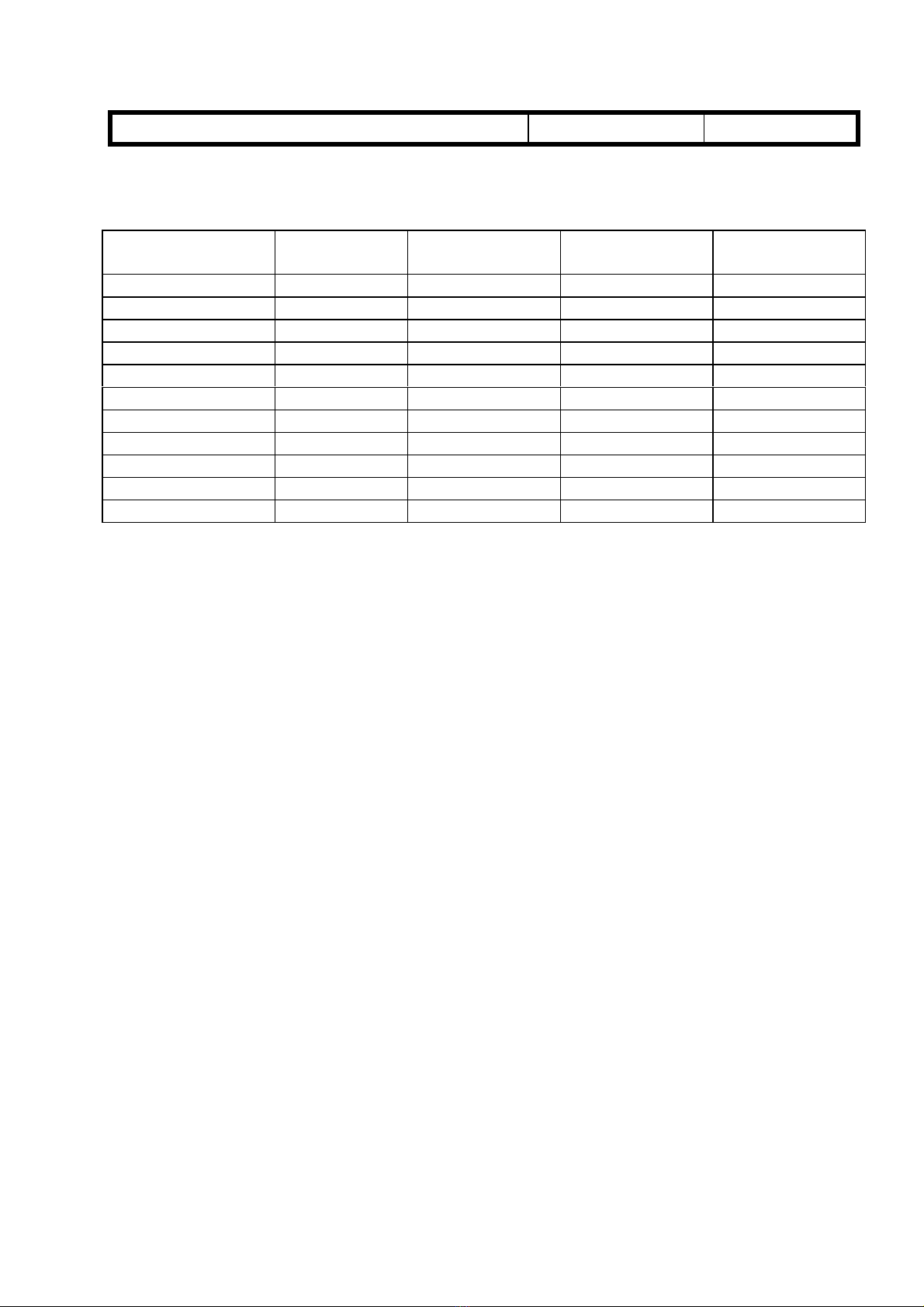
Controller Board Part Number and Software Version:
Product Code Controller Board Software Version
A649-00 A6495100Q ver. 2.30