Copyright ©2004 G418-8600
Printed in Japan
Quick Installation Guide
○○○○○○○○○○○○○○○○○○○○○○○○○○○○○○○○○○○○○○○○○○○○○○○○○○○○○○○○○○○○○○○○○○○○○○○○○○○○○○○○○○○○○○○○○○○○○○○○○○○○○
○○○○○○○○○○○○○○○○○○○○○○○○○○○○○○○○○○○○○○○○○
○○○○○○○○○○○○○○○○○○○○○○○○○○○○○○○○○○○○○○○○○○○○○○○○○○○○○○○○○○○○○○○○○
○○○○○○○○○○○○○○○○○○○○○○○○○○○○○○○○○○○○○○○○○○○○○○○○○○○○○○○○○○○○○○○○○○○○○○○○○○○○○○○○○○○○○○○○○○○○○○○○○○○○○
Connecting to the Computer
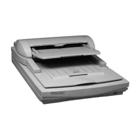
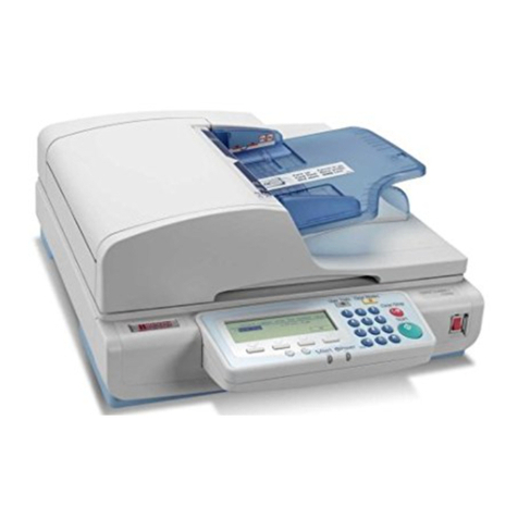
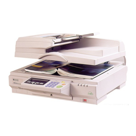
This scanner can be connected to the computer
with a SCSI and/or USB interface.
You can connect the scanner to two computers
at the same time. One with the SCSI interface,
and one with the USB 2.0 interface. Though,
you cannot use the scanner at the same time
from two computers. Interfaces are switched
automatically when you change from one of the
computer to the other.
Important
❒The SCSI interface of this unit is of the 50-
pin half-pitch (pin-type) type. Connect a
shielded SCSI-2 compliant with ANSI stan-
dards or a SCSI-3 (Ultra-SCSI) cable.
❒It is possible that malfunction occurs or data
is lost when more than one SCSI ID's exists
simultaneously. Adjust the settings such that
the SCSI ID of this unit does not coincide
with the ID of another SCSI device.
❒Keep the total length of the SCSI cable in-
cluding the cable inside the PC to a maxi-
mum of 1.5m (4.9 feet) when using the
SCSI-3 (Ultra-SCSI) and 3m (9.8 feet) when
using the SCSI-2.
❒Some combinations of the SCSI board of
your computer and daisychained peripherals
might cause an incorrect operation.
Please contact and ask your service
representative about the recommended
SCSI board.
❒If you connect this unit to other SCSI devices
through a daisy chain, it may not work
properly. In this case, connect only this
unit to the computer.
Connecting the SCSI Interface
(When the Scanner is at the End of
the Daisy Chain)
Shut down the computer and all of
the SCSI connected devices.
Daisy chain the computer, scanner
and SCSI connected devices.
ADC018S
Note
❒Connect the SCSI cable to either one side of the
connectors.
Open the cover of the switch box
on the lower left of the front side of
the scanner.
Note
❒Push the knob of the cover to the left and pull
the cover to open.
Confirm the DIP Switch NO.3 is in
the OFF position.
ADC019S
When you do not use the USB
connection
Changing the DIP Switch settings enables high-
speed data transfer. This is available with SCSI
connection, the USB and the optional IEEE1394
connection cannot be used with this setting.
ASet the DIP Switch NO.2 to the OFF position.
SCSI synchronous transmission is enabled.
Set the SCSI ID by rotating the Rotary
Switch.
ADC017S
Connecting the SCSI Interface
(When the Scanner is not at the End
of the Daisy Chain)
Shut down the computer and all of
the SCSI connected devices.
Daisy chain the computer, scanner
and SCSI connected devices.
ADC020S
Open the cover of the switch box
on the lower left of the front side of
the scanner.
Note
❒Push the knob of the cover to the left and pull
the cover to open.
Set the DIP Switch NO.3 to the ON
position.
ADC021S
Built-in SCSI terminator is disabled.
When you do not use the USB
connection
Changing the DIP Switch settings enables high-
speed data transfer. This is available with SCSI
connection, the USB and the optional IEEE1394
connection cannot be used with this setting.
ASet the DIP Switch NO.2 to the OFF position.
SCSI synchronous transmission is enabled.
Set the SCSI ID by rotating the Rotary
Switch.
ADC017S
Connecting the USB Interface
Note
❒Please use the recommended USB cable. Using
other cables might occur an irregular operation.
As for the recommended cables, please ask your
service representative.
Open the cover of the switch box
on the lower left of the frontside of
the scanner.
Note
❒Push the knob of the cover to the left and pull
the cover to open.
Confirm the DIP Switch NO.2 is in
the ON position.
ADC080S
Note
❒If the DIP Switch NO.2 is set to OFF, set it to
ON. The scanner will not be detected if the
switch is set to OFF.
Connect the USB cable to the USB
connector.
ADC022S
Connect the other side of the cable
to the USB connector on your com-
puter.
○○○○○○○○○○○○○○○○○○○○○○○○○○○○○○○○○○○○○○○○○
Connecting the Power Code
○○○○○○○○○○○○○○○○○○○○○○○○○○○○○○○○○○○○○○○○○○○○○○○○○○○○○○○○○○○○○○○○
Detecting
the Scanner
Appendix: Turning the Power On/Off
Turning the Power On when
Connected with SCSI Interface
Turn the power on from the farthest devices from
the computer on the daisy chain. Start the
computer last.
Note
❒The scanner will not be detected if you start the
computer first.
Turning the Power On when
Connected with USB Interface
There is no order to turn on the power when you
connect the scanner with USB Interface.You can
turn on either the scanner or the computer first.
○○○○○○○○○
○○○○○○○○○○○○○○
GB GB EN USA
Turning the Power Off
There is no order to turn off the power. You can
turn off either the scanner or the computer first.
○○○○○○○○○
This section explains how to connect this
machine to a power source, using a bundled
AC power cord.
WARNING
•Do not use with a power source with a voltage
different from the specified voltage.Do not use
a power outlet with multiple devices plugged
in. These could create the risk of fire or elec-
tric shock.
•Avoid the use of an extension cord.
•Do not damage, break, twist or modify the
Power Cord. Placing heavy objects on the
cord, pulling on or bending it excessively can
damage the Power Cord, creating the risk of
fire or electric shock.
•Never touch or unplug the power plug with wet
hands. This can create the risk of electric
shock.
CAUTION
•When unplugging from an outlet, be sure to
grasp the plug when pulling. Never pull on
the cord. This could damage the cord creat-
ing the risk of fire or electrical shock.
Confirm that the power switch is set
to off.
ADC124S
Confirm the lock screws on the back
of this machine are removed and the
holes left by the removed screws
are covered with the cap, and con-
firm that the lock lever is set to the
"Unlock" position.
ADC089S
Important
❒Turning the power on leaving the lock lever
to the "Lock" position and/or turning the
power on without removing the screws could
result not only in failure in scanning but in
malfunction of this machine.
Push the power cord plug all the
way into the power connector on
this machine.
ADC026S
Note
❒Be sure to use the power cord that comes with
this machine.
Insert the power plug into the power
outlet.
Power on the scanner.
ADC125S
Start the computer.
The installation completes here for the
computer with the operation systems, Windows
95 and Windows NT4.0. For the computer with
other operation systems, “Plug & Play”detects
the scanner and the “Found New Hardware
Wizard”automatically starts.
In the Wizard, select [Sear ch for a
suitable driver for my device [rec-
ommended]], and continue the
“Found Ne w Hardware Wizard” to
the end, according to the instruc-
tion on the displa y.
Note
❒When an instruction to set the Windows system
CD-ROM appears on the display in the course
of the installation, follow the instruction accord-
ingly.
❒Even when “No approval of the logo test” ap-
pears on the display, you can continue the in-
stallation by clicking [continue].

