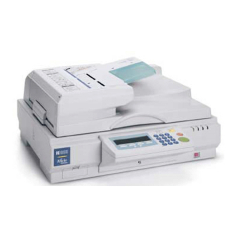
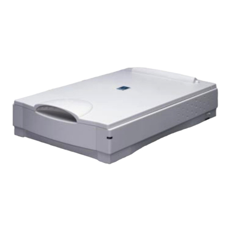
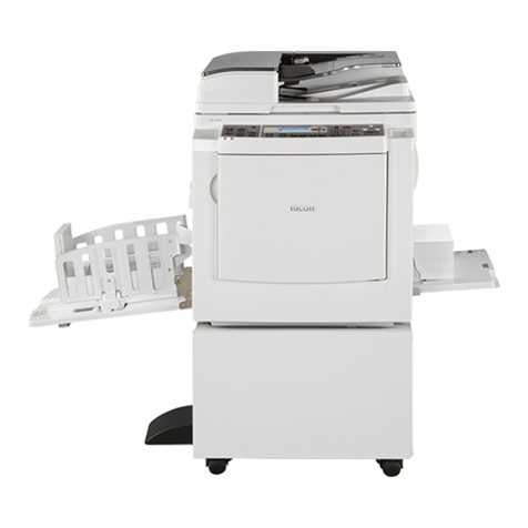
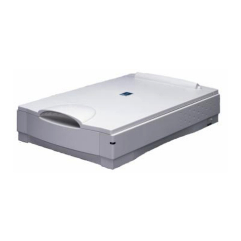
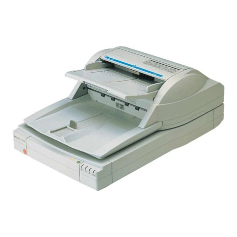
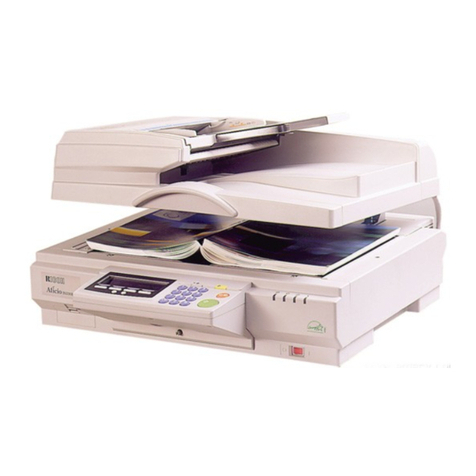
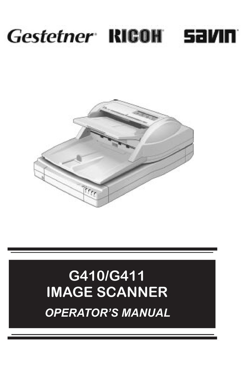
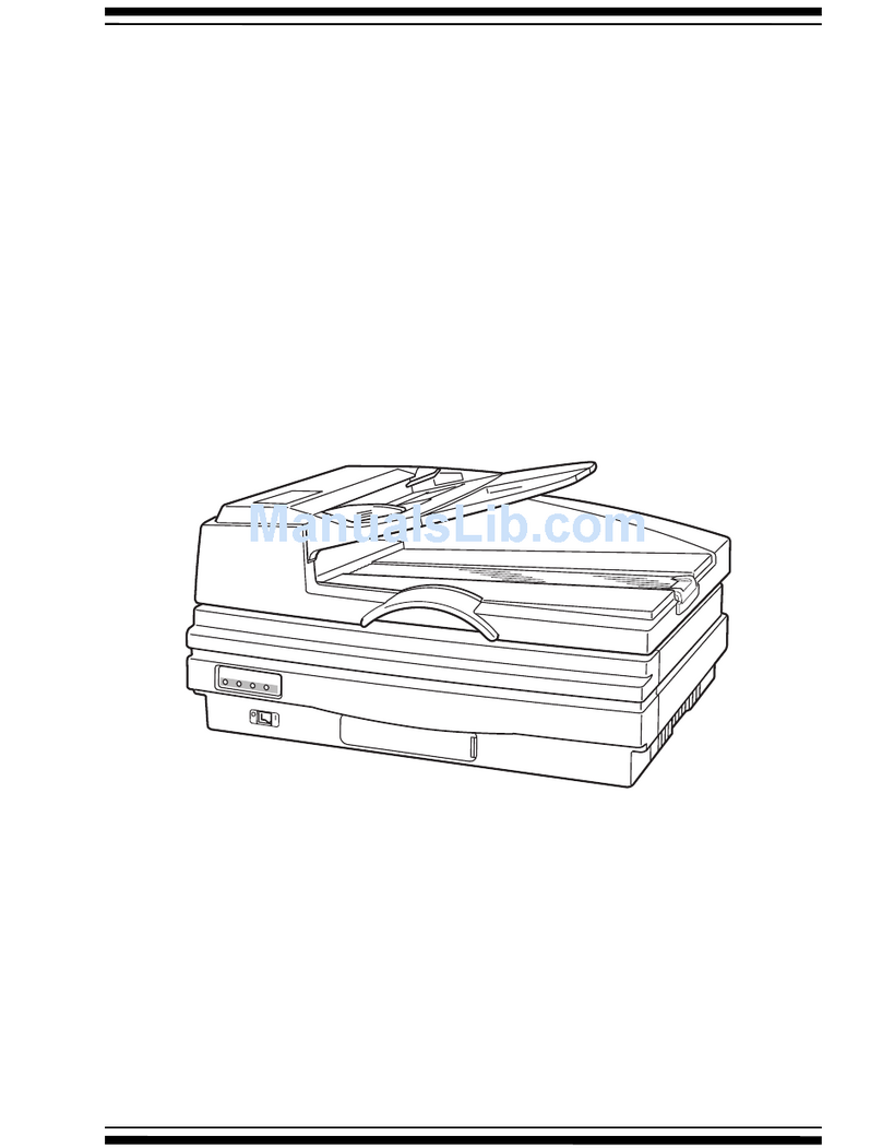
Ricoh HS2P PLUS User manual

RICOH Technical Bulletin PAGE: 1/2
Reissued: 23-Mar-00
Model: IS450 / IS450DE/V Date: 17-Feb-00 No.: RG407001a
RTB Correction
The items in bold italics have been corrected or added.
Subject: Diffarence between HS2P and HS2P+ Prepared by: E. Fukuyama
From: Technical Services Dept., GTS Division
Classification: Troubleshooting
Mechanical
Paper path
Part information
Electrical
Transmit/receive
Action required
Service manual revision
Retrofit information
Other ( )
In preparation for HS2P+ mass production set to begin later this month, this RTB will
explain the differences between the HS2P and HS2P+. Therefore, there will be no Service
Manual released for the HS2P+.
The HS2P+ was developed for use with the KOFAX VRS system only, and many of its
components have been modified from the HS2P. After being connected to the RSCU
board, the KOFAX VRS board acts as an interface to forward the image data to the PC.
The following is a description of the differences between the HS2P and HS2P+, along with
a list of the sections of the Service Manual that require revision.
The following are the revisions made to the HS2P+ from the HS2P.
General differences from the HS2P:
1. In order to enable Auto Original Detection as well as Auto Skew Detection, the color of
the Platen Cover Sheet has been changed from white to black.
Modifications made to: Platen Cover Sheet, ADF Guide Plate, and Rear Roller.
2. In order to enable Grayscale Image Processing for the rear side of the scanned original,
a 32MB SIMM has been added.
Modifications made to: RCU Board.
3. A KOFAX VRS board is used as the interface between the scanner and PC.
Since this video interface is now used for scanner/PC communication, the SCSI I/F will
only be used by the service technician to diagnose problems with the scanner.
Therefore, a cover has been placed over the two SCSI interfaces.
Note: Ricoh’s product liability is limited to the scanner mainframe, the harness that
connects to the VRS interface board, and the connector on the VRS board for this
harness.
4. A Shading Calibration Sheet has been registered as a Service Part.
Since the rear roller in the HS2P+ is black, it is not possible to use the roller for rear side
shading. This is why a Shading Calibration Sheet was added. The shading data is
controlled by the KOFAX driver.
The RSCU board sends the data to the VRS board, and the data is not saved inside the
HS2P+ itself.
RICOH Technical Bulletin PAGE: 2/2
Reissued: 23-Mar-00
Model: IS450 / IS450DE/V Date: 17-Feb-00 No.: RG407001a
Differences in internal components:
HS2P HS2P+Page-
Index Part number Description Part number Description
17-14 G4074039 Platen Cover Sheet G4134039 Platen Cover Sheet Black
9-4 G4073345 ADF Guide Plate G4133347 ADF Guide Plate Black
11-17 G4083501 Rear Roller G4133501 Rear Roller Black
23-6 G4085100 RCU Board G4135101 ERCU Board
---- ----- ----- G4135150 SIMM 8M X 32 BIT 60ns
---- ----- ----- G4133590 Shading Calibration Sheet
---- ----- ----- G4131056 SCSI I/F Cover

HS2P PLUS
(Machine Code: G413)
Service Manual
Issued on February16, 2000
Ricoh Co., LTD

16 February 2000 SPECIFICATIONS
1-1
Overall
Information
1. OVERALL MACHINE INFORMATION
1.1 SPECIFICATIONS
1.1.1 MAIN BODY
Scanning method: Flat-bed with ADF
Book scan: Horizontal: Max. 298 mm [11.7"]
Vertical: Max. 432 mm [17.0"]
ADF: Document size:
Width: 69 ~ 298 mm [2.7" ~ 11.7"]
Length: 120 ~ 2,000 mm [4.7" ~ 78.5"]
All pages in a document must be the
same width
Document weight: 41 ~ 128 g/m2[11 ~ 34 lb.]
ADF capacity:
150 sheets (64 g/m2[20 lb.])
110 sheets (105 g/m2[24 lb.]/A4, A5, LT, HLT)
80 sheets (105 g/m2[24 lb.]/A3, DLT)
Stack height must be less than 15 mm [0.6"]
Scanning resolution: Simplex mode:
Main scan: 100 ~ 800 dpi (in 1 dpi steps)
Sub scan: 100 ~ 800 dpi (in 1 dpi steps)
Duplex mode:
Main scan: 100 ~ 600 dpi (in 100 dpi steps)
Sub scan: 100 ~ 600 dpi (in 100 dpi steps)
Grayscales: 8 bits/pixel
Initialization time: About 15 seconds
Scanning speed: 0.65 s/200 dpi (A4, binary picture mode)
Scanning throughput: Simplex mode: 55 ppm/200 dpi
(A4, binary picture mode)
Duplex mode: 86 ipm/200 dpi
(A4, binary picture mode)
(Counted from the second page)
Interface: Expansion Interface: 60 pin
SCSI: The specification of SCSI I/F are only for
field service purpose.
Power: 1) 102 to 138 V ac (45 to 65 Hz)
2) 187 to 276 V ac (45 to 65 Hz)
Power consumption
(without all possible options): Standby: 90 W Max.
Scanning: 120 W Max.

SPECIFICATIONS 16 February 2000
1-2
Operating environment: Temperature: 10 to 32°C [50 to 90°F]
Humidity: 20 to 80% RH
Weight: Less than 27 kg [59.5 lb.]
Dimensions (W x D x H): 470 x 677 x 278 mm [18.5" x 26.7" x 10.9"]
1.1.2 ENDORSER
Number of printable characters: 19 characters (max)
Character set: 43 characters
0123456789#./-:,’AB ····Z
Character size: 1.6 (W) x 2.8 (H) mm
Character pitch: 2.4 mm ±20%
Printable lines: 1 line (main scan direction)
Inking: Ink roll type
Ink refill: Ink roll exchange
Ink color: Purple
Print position: a: 7 ±4 mm
b: 0 ±5 mm
Document
front side
Document Feed Direction
a
b
G413V506.WMF

COMPONENT LAYOUT 16 February 2000
1-4
1.2.2 REAR VIEW
No. Name Function
7 Reset switch If this is pressed, the machine is reset.
8DIP switches Used to select various scanning modes and test
modes.
9Interface for reverse side
scanning
(Duplex model only)
Interface for the video signal during reverse side
scanning.
10 Video connector For connecting the video cable
11 SCSI ID rotary switch Used to select the SCSI ID and to select diagnostic
tests. Note that positions 8 and 9 are interpreted as
SCSI ID 7.
12 Power plug inlet For connecting the power cord.
13 ADF cover Open this cover to clear paper jammed at the input
side.
14 SCSI connectors cover
and SCSI connectors (For connecting the SCSI cables.)
G413V501.WMF
13
101112 789
14

16 February 2000 DRIVE LAYOUT
1-7
Overall
Information
1.3.2 ADF
No. Name Function
8 Feed roller Feeds the top page of the original into the ADF.
9Pick-up roller Picks up and transports the top page of the original on
the document table.
10 Separation roller Stops the lower pages of the original while allowing the
top one to pass.
11 Black roller Feed the scanned original.
12 Feed-out rollers Feed the scanned original onto the exit table.
13 Paper transport drum Transports the original to the scanning position.
14 Paper transport rollers Hold the original against the paper transport drum.
G413V507.WMF
11
12
10
9
13
14 8

ELECTRICAL COMPONENT LAYOUT 16 February 2000
1-8
1.4 ELECTRICAL COMPONENT LAYOUT
1.4.1 SCANNER
No. Name Function
1Home position sensor Detects whether the first scanner is at the home
position.
2 SCU Controls the overall scanner function.
3 Lamp Stabilizer Provides ac power to the exposure lamp.
4SBU Contains the CCD, and outputs a video signal to the
SCU.
5 Scanner Motor Drives the scanners.
6 SOP This contains the scanner indicator lamps.
7 PSU Provides dc voltages to the system.
8 IOB Controls the mechanical parts of the scanner.
9 SIMM 32MB RAM
10 ERCU Outputs a video signal of the reverse side of the original
to the SCU.
11 Exposure lamp Illuminates the original for exposure.
G413V504.WMF
6
7
5
4
32
1
8
9
10
11

16 February 2000 ELECTRICAL COMPONENT LAYOUT
1-9
Overall
Information
1.4.2 ADF
No. Name Function
12 ADF interlock switch Detects whether the ADF cover and platen cover are
open or closed; cuts the power supply to the machine.
13 Paper transport motor Drives the paper transport drum.
14 Feed sensor Detects when a document is just before the feeding
position.
15 Read sensor Synchronizes the original exposure timing.
16 Paper feed motor This drives the pick-up and feed rollers.
17 CIS Contains the CCDs and LEDs that scan the reverse
side of the original.
18 EDU Controls the mechanical parts of the endorser.
19 Endorser solenoid Moves the paper holding plate to hold the original at the
endorser’s printing position.
20 Relay sensor Checks for original misfeeds.
21 Feed-out sensor Detects when a document is at the feed-out position.
22 Document sensor Detects when a document is placed on the document
table.
23 RADU Controls the mechanical parts of the ADF.
24 Document table position
sensor Detects if the document table is at the feed position or
not.
25 Pick-up clutch Controls pick-up roller rotation.
26 Document table lift
clutch Switches on to lift the document table up or down.
G413V505.WMF
19
18
17
16
15
14
13
26
20
21
22
23
24
25
12

IMAGE PROCESSING 16 February 2000
2-16
2.4 IMAGE PROCESSING
2.4.1 OVERVIEW
The CCD generates two analog video signals. The SBU (Sensor Board Unit)
converts these analog signals to 8-bit digital signals, then it sends these digital
signals to the SCU (Scanner Control Unit) board through the IOB board. The IPU
(Image Processing Unit) IC on the SCU does the image processing, then the image
data goes to the computer through the Memory Control IC and the SCSI controller.
The CIS (Contact Image Sensor) unit in the duplex for reverse-side scanning
outputs two digital signals. The IPU on the ERCU (Reverse Control Unit) board
does the image processing, then the image data goes to the VRS Board through
the SCU.
CCD
SCU
CIS
CCD
DRAM
IPU
Memory
Control
IC
SCSI
Control
IC
SBU
IOB
ERCU
IPU
Memory
Control
IC DRAM
VRS
Board
G413D508.WMF

IMAGE PROCESSING 16 February 2000
2-18
2.4.3 IPU (IMAGE PROCESSING UNIT)
Overview
The image data from the SBU goes to the IPU IC on the SCU board, which carries
out the following processes on the image data.
1. Auto shading
2. Magnification
3. Mirror processing
4. Filtering (MTF and smoothing)
5. γ(gamma) correction
6. Grayscale processing
7. Binary picture processing
8. Error diffusion
9. Dithering
10. White/black conversion
The image data then goes to the memory controller IC.
IPU
AD
AD
C
C
D
Selector
Odd
Even 8Memory
Controller SCSI SCSI
8
8
8
Analog Processing
IC 1
8
Analog
Processing IC 2 VRS
Borad
SBU
SCU
G413D505.WMF

16 February 2000 IMAGE PROCESSING
2-19
Detailed
Descriptions
Image processing path
The following image processing is for the scanner. The image processing for each
of these units is explained in separate sections.
Shading Correction
The machine scans the white plate opposite the ADF exposure glass to make a
white waveform. Shading correction prevents uneven images caused by
fluctuations in scanned data due to changes in light intensity and CCD sensitivity.
Magnification
Reduction and enlargement in the sub scan direction are done by changing the
scanner motor speed or paper transport motor speed in the ADF. However,
reduction and enlargement in the main scan direction are done by the IPU.
Mirror Processing
A mirror image of the original must be made for output.
Filtering
There are two software filters: the MTF filter and the smoothing filter. The MTF filter
emphasizes sharpness, and is used with text-only documents or documents that
contain text and photo areas. The smoothing filter is used for photo-image
documents.
Gamma (
γ
γγ
γ
) Correction
The gamma curve corrects the response of the CCD to grayscales in the original.
Grayscale Processing
This process generates up to 256 image density levels for each pixel.
Dithering
Dither processing produces good quality grayscale images of photo originals.
IPU Memory
Controller
SBU
Filtering
Magnification/
Mirror Process
γ
correction
Shading
correction Dither/
Error Diffusion Binary process White/black
conversion
SCU
G413D500.WMF

IMAGE PROCESSING 16 February 2000
2-20
Error Diffusion
The error diffusion process reduces the difference in contrast between light and
dark areas of a halftone image. Each pixel is corrected using the difference
between it and the surrounding pixels. The corrected pixels are then compared with
a matrix table.
Binary Picture Processing
Each video signal level is converted from 8-bit to 1-bit (black and white image data)
in accordance with a threshold value.
White/Black Conversion
Inverts the image (converts from white to black and vice versa).
After video processing, the data goes to the host computer through the memory
and SCSI controllers.

16 February 2000 REVERSE SIDE SCANNING
2-21
Detailed
Descriptions
2.5 REVERSE SIDE SCANNING
2.5.1 OVERVIEW
The CIS (Contact Image Sensor) unit [A], which is in the document exit area, scans
the reverse side of the document.
The front side of the document is scanned first. Then the document goes to the
reverse side scanning area. The black roller [B] pushes the document against the
CIS unit for scanning and feeds the document to the exit area.
The position of the CIS unit is fixed in the scanner, and cannot be adjusted in the
field.
G413D516.WMF
[A]
[B]

16 February 2000 REVERSE SIDE SCANNING
2-23
Detailed
Descriptions
2.5.3 IMAGE SCANNING
As explained on the previous page, the CIS unit contains five CCDs. The analog
signal from each CCD goes to an analog processing IC. The function of the analog
processing circuit is the same as for the SBU. Then, these go to the IPU on the
ERCU board.
The ERCU board contains the IPU and memory controller ICs for image
processing. The image processing in the IPU is the same as for the IPU in the SCU
except for the shading correction.
After image processing, the data goes to the PC through the VRS board on the
SCU.
AD
AD
AD
AD
AD
C
C
D
L
E
D
IPU
Shading
Correction
Odd
Even 8
8
Memory
Controller
8
SCSI SCSI
8
Analog
Processing
Circuit
Analog
Processing
Circuit
Analog
Processing
Circuit
Analog
Processing
Circuit
Analog
Processing
Circuit
ERCUCIS
SCU
VRS Board
G413D504.WMF

16 February 2000 MAIN PCBS AND THEIR FUNCTIONS
2-27
Detailed
Descriptions
2.8 MAIN PCBs AND THEIR FUNCTIONS
2.8.1 BOARD STRUCTURE
For the main function of each PCB, refer to the Electrical Component Layout
section.
H.P Sensor
Lamp
Stabilizer
Operation Panel
Cooling
Fan
Scanner
Motor
SBU
Exposure
Lamp
Clutches
Sensors
Motors
ADU
IOB
SCU
ERCU
CIS Unit
Endorser Unit
VRS PSU
ADF
Main Frame
G413D509.WMF

MAIN PCBS AND THEIR FUNCTIONS 16 February 2000
2-28
2.8.2 SCU (SCANNER CONTROL UNIT)
This is the main board. The functions of each component are as follows.
CPU: HD6413002F
•Scanner sequence control
•Clock/timer control
•DMA control
IPU (Image Processing Unit):
•Shading correction
•Image processing (Mirror image, reproduction ratios, MTF correction, binary
picture processing, edge extraction, and so on)
Memory Controller:
•Stores the image data from the IPU in the memory (DRAM 32 Mbytes x 2).
•Address control when recalling the data from the memory.
SCSI controller: SCSI interface controller.
SRAM: Work area (32 kbytes)
EPROM: Contains the program.
Enhanced I/O (EIO):
•Extension for the I/O port.
•DIP switches (mode selection), rotary switches (SCSI ID setting), and a push
switch (reset button) are connected.
E2PROM: Holds the book, ADF, and lamp counter values.
IPU
SCSI
Controller
EPROM
4 Mbit (x16)
SRAM
256 kbit (x8)
E2PROM
2 kbit
Reset IC
CPU
EIO
SCSI ID
Rotary
SW
DIP SW
SCSI
Terminator
OSC
OSC
DRAM
16 Mbit (x16)
Odd
Even
CPU Bus
OSC
VRS
ERCU
IOB
SCSI 1SCSI 2
SCU
Image data Signal line
SEL
Memory
Controller
G413D512.WMF

16 February 2000 DIP SWITCHSETTINGS
4-1
Service
Tables
4. SERVICE LEVEL FUNCTIONS
4.1 DIP SWITCH SETTINGS
The factorydefault position of the dip switches is indicated in the diagram below.
After changing a dip switch setting, either switch the power off and then on again,
or press the reset switch.
Dip Switch Setting Table
Dip Switch Item Contents
1234 6758
ON
SCAM function
switch OFF:SCAM function enabled
ON: SCAMfunctiondisabled
1234 6758
ON
SCSI synchronous
transfer switch OFF:SCSI synchronous transfer enabled
ON: SCSI synchronous transfer disabled
1234 6758
ON
Internal SCSI
terminator switch OFF:InternalSCSI terminator on
ON: Internal SCSI terminator off
Service level test modes
1234 6758
ON
Various tests for the scanner are carried out using dip switches 5 to 8.
Within each test mode, tests are selected byturning the SCSI ID rotary
switch, and the machine's condition is indicated bythe four LEDs on the
covers.
Note the position of the SCSI ID rotaryswitch before you change it.
To return to normal operation mode after testing, switch dip switches 5 to 8
all off, return the SCSI ID rotaryswitch to its operating position, then press
the reset button.
1234 6758
ON
Demonstration modeScanner demonstration in book and ADF modes;
Refer to Table A later in this section.
1234 6758
ON
Component test
mode Each component can be tested; refer to Table B later
in this section.
1234 6758
ON
Sensor test mode Each sensor can be tested; refer to Table C later in
this section.
1234 6758
ON
Self diagnostic modeResults of the diagnosis are indicated through a
combination of the LEDs on the covers; refer to Table
D later in this section and “Troubleshooting” in
section 6.
1234 6758
ON
ON
OFF
G413M500.WMF

DIP SWITCHSETTINGS 16 February 2000
4-4
Table D: Self Diagnostic Mode
During the self-diagnostic mode, the scanner performs the following tests.
1) Home position error check
2) Exposure lamp error check
3) White level error check
4) Document table error check
5) SCU error check
6) RCU error check
7) Memory error check
If the scanner detects errors, the first error that occurred is indicated bya
combination of four LEDs.
LEDs
Error Items Power On
(Green) Machine
Busy(Green) Document in
Place (Green)Error
(Red)
SCU error Blinking ——Blinking
RCU error Blinking —On Blinking
Home position error Blinking Blinking Blinking On
Exposure lamp error Blinking Blinking On On
White level error Blinking Blinking ——
Memoryerror (Simplex)Blinking ———
Memoryerror (Duplex)—Blinking ——
On: LED on Blinking: LED blinking —: LED off
Table E: Counter Indication Mode
Rotary Switch Table
SCSI ID RotarySwitchNo. Contents
0Not used
1Units
2Tens
3Hundreds
4Thousands
5Ten thousands
6Hundred thousands
7Millions
8Not used
9Not used

ERROR INDICATION 16 February 2000
6-2
6.3 ERROR INDICATION
If the self-diagnostics find an error, the error is displayed bya combination of the
four LEDs on the scanner. If the dip switches on the rear of the machine are set up
for normal operation, the error is indicated roughlyfor users. When the dip switches
are set to the self-diagnostic mode position, the system error is indicated in detail
for technicians.
6.3.1 USER LEVEL ERROR INDICATION
LEDs
Conditions Contents Originals on
the table Green Green Green Red
Machine
Initialization Overall
machine check On On On On
Demonstration
Mode On On On On
No On Off Off OffNormal mode Yes On Off On Off
No On Off Blinking Off
Stand-by
Scan wait
mode Yes On Off Blinking Off
No On On Off OffScanning Normal mode YesOnOnOnOff
ADF cover switch open On Off Off On
Document jam On Off Blinking On
Document misfeed On Off On On
Document table error On Off BlinkingBlinking
User-visible
Error Conditions
Endorser error BlinkingBlinking On Off
System Error BlinkingBlinkingBlinkingBlinking
On: LED on Blinking: LED blinking Off: LED off
6.3.2 TECHNICIAN LEVEL ERROR INDICATION
LEDs
Error Items Green Green Green Red
Memoryerror (Simplex)Blinking Off Off Off
Memoryerror (Duplex)Off Blinking Off Off
Exposure lamp failure Blinking Blinking On On
White level error Blinking Blinking Off Off
Home position error Blinking Blinking Blinking On
SCU error Blinking Off Off Blinking
RCU error Blinking Off On Blinking
On: LED on Blinking: LED blinking Off: LED off
Table of contents
Other Ricoh Scanner manuals

Ricoh
Ricoh IS200e User manual

Ricoh
Ricoh Capella-NB1e User manual

Ricoh
Ricoh fi-8040 Manual

Ricoh
Ricoh Priport JP1030 User manual

Ricoh
Ricoh Aficio IS420 User manual

Ricoh
Ricoh IS760 User manual

Ricoh
Ricoh Wide Format Color Scanner User manual

Ricoh
Ricoh IS100e User manual

Ricoh
Ricoh fi-70F Manual

Ricoh
Ricoh fi-8040 Use and care manual

Ricoh
Ricoh IS01 - IS 01 User manual

Ricoh
Ricoh ImageReader FB735 User manual

Ricoh
Ricoh Scanner User manual

Ricoh
Ricoh G413 Owner's manual

Ricoh
Ricoh IS300e User manual

Ricoh
Ricoh Scanner User manual

Ricoh
Ricoh IS330DC - IS - Flatbed Scanner User manual

Ricoh
Ricoh G410 User manual

Ricoh
Ricoh Aficio 2105 User manual

Ricoh
Ricoh IS01 User manual