Ritchie 1422 Technical Document

Instruction Manual
& Operating Guide

Signed:-
EC Declaration of Conformity
Equipment: .............................................................................................................
Model No: .............................................................................................................
Serial No: .............................................................................................................
in accordance with BS EN ISO/IEC 17050-1:2004
David Ritchie (Implements) Ltd.,
Carseview Road, Forfar, Scotland DD8 3BT
declare that:
in accordance with the following directive:
2006/42/EC Conforms with the essential requirements of the Machinery Directive
and its amending directives
Robert Ritchie Al agr E
Agricultural Sales Director
at:- David Ritchie Implements Ltd. Forfar, UK
on:- 20th December 2010
8 Bale Windrower Accumulator
1422
has been designed and manufactured to the following specifications:
BS EN ISO 12100 -1: 2003 Safety of Machinery - Basic concepts, general principals for design - Basic
terminology, methodology.
BS EN ISO 12100 -2: 2003 Safety of Machinery - Basic concepts, general principals for design -
technical principals and specifications.
BS EN 982: 1996
Safety of machinery. Safety requirements for fluid power systems and their components - Hydraulics
BS EN ISO 4254-1:2009
Agricultural machinery - Safety - Part 1: General requirements
BS EN ISO 13857:2008
Safety of machinery - Safety distances to prevent hazard zones being reached by upper and lower limbs.
BS EN ISO 14121-1: 2007
Safety of machinery - Risk assessment - Part 1: Principles

Contents
8 Bale Windrower Accumulator - Model 1422
Pages
Foreword ........................................................................................... 4
Warranty ........................................................................................... 5
Intended Use ..................................................................................... 5
Safety Information......................................................................... 6, 7
Features and Specifications ............................................................... 8
Machine Overview ............................................................................. 9
Preparation ................................................................... 10, 11, 12, 13
Setting Up and Adjustment ............................................................. 14
Optional Hydraulic Release Kit (1422-600) ................................ 15, 16
Operation .................................................................................. 17, 18
Further Adjustments ........................................................................ 19
Parts List .................................................................................... 20, 21
Lubrication & Maintenance ............................................................. 22
3

4
Foreword
The Cook 8 Bale Windrower Accumulator has
been designed for the grouping together of
bales and is not intended for any other use.
David Ritchie Implements shall not be liable
for damage resulting from misappropriate
use of the machine. The user shall bear all
responsibility.
Intended use also comprises adherence to the
operating, maintenance and servicing
instructions contained in this manual.
The machine must only be used in perfect
working condition. Any functional disorders,
especially those which affect the health and
safety of personnel must be rectified
immediately.
The Bale Accumulator must only be used by
an experienced, competent operator who has
been trained in the use of the machine and
who has read the operator’s instruction
manual.
Following the setting up, operating and
maintenance instructions contained in the
manual should allow the operator to achieve
the best performance from the machine,
resulting in increased reliability.
Operator’s should read carefully all safety
notes contained within the manual prior to
using the machine in order to help avoid
dangerous situations, expensive repairs and
prolonged downtime. In addition operator’s
should also read any relevant legislation
regarding health and safety and accident
prevention applicable to the country in which
the machine is to be used.
The right to alter specifications, equipment
and maintenance instructions at any time,
without notice is reserved as part of our policy
of continuous development and
improvement.
No liability can be accepted for inaccuracies
or omissions in this manual, although every
possible care has been taken to make it as
complete and accurate as possible.
Owners who encounter a problem not
covered in this manual should contact David
Ritchie Implements Ltd at the address given
on the rear cover of the manual, or consult
their local Ritchie dealership.

5
Warranty
The machine should be checked over at time
of delivery for transport damage. Check also
that the specification is complete and that the
data plate contains the serial number of the
machine. All claims must be delivered to the
manufacturer in written form within 48 hours.
David Ritchie Implements Ltd. guarantee
subject to certain conditions that the goods
supplied will be free of defects both in material
and workmanship.
The following conditions apply:-
• The machine should only be used for the
purpose indicated in this manual.
• Service and warranty work is carried out only
by authorised Ritchie dealers.
• The original specification of the machine has
not been subject to unauthorised
modification.
Correct operation of the machine and regular
maintenance will help to prevent breakdowns.
If however operating trouble is experienced
during the warranty period the following
actions should be adopted:-
Notify the dealer immediately from whom the
machine was purchased, quoting the model
and serial number.
Do not operate the machine. Damage
resulting from failure to report a fault may
not be covered by warranty.
The manufacturer cannot accept liability for
damage to machines or third party through
operational negligence.
Intended Use
The Cook 8 Bale Windrower Accumulator
model 1422, is designed to work behind most
modern balers, where bale sizes are 14” - 16”
high and 18” or 19” wide. Bales should be in
the region of 36” in length and not more than
42”.
The Bale Accumulator is attached to the Bale
Chamber to accept bales via a front chute.
Each bale is guided through the Accumulator
until 2 rows of 4 bales have been formed. The
Windrower Accumulator allows the operator
to hold the pack whilst the next pack is being
formed, with the operator releasing when
convenient. When released behind the
machine packs are ready for handling with
the ‘Ritchie Flat Eight Grab’.
The machine is designed to be used by a single
operator only (tractor driver).
Inappropriate Use
The machine must not be used for purposes
other than those indicated in this manual.

Safety Information
Please read these instructions carefully.
Ignoring these instructions could result
in personal injury or damage to the
machine.
These instructions apply to all personnel
involved with the operation, maintenance and
servicing of the machine.
General
The machine must only be used by an
experienced, competent operator who has
been trained to use the machine.
The operator should consult the tractor
handbook, and Baler Instruction book for
information and instruction on safety issues.
Only operate this machine from the tractor
seat (work station).
Never allow personnel to ride on the machine,
either on the road or in the field.
Do not modify any part of the machine unless
modifications or additions are approved by the
manufacturer. This also applies to welding
work.
Do not use the machine if a malfunction
occurs as this could result in damage to the
machine.
Warn bystanders to keep clear of the machine
whilst operational.
Hay and Straw are flammable - so always keep
the machine in a clean condition away from
open fires and smoking materials.
Keep a fire extinguisher in the tractor cab!
Before and During Operation
Never leave the tractor cab while the
engine is running. Always switch off and
remove the ignition key and apply the
tractor handbrake.
Take particular care when mounting the
implement to the Bale Chamber. Always
position the machine on flat level concrete or
tarmac.
Never work on ground exceeding 8° in
inclination.
6
Transportation and Storage
Before travelling on public roads ensure the
machine is free of loose material and
equipment.
Move the Drawbar from the centre (working
position) to the side attachment point (road
transport position, page 11).
Secure the rear door by fitting the bolt and
wing nut as described on page 12, and fold
the rear section into the road transportation
position.
Road speed should not exceed 20 mph
(30 km/h).
When turning or at bends take the width and
length of the machine into consideration.
Take extra care when reversing the machine.
When stopped, always use the parking brake.
When storing the machine- clean thoroughly.
Position the machine on flat level concrete or
tarmac where it presents no hazard to people
or animals.

7
After servicing is complete check all nuts and
bolts have been tightened satisfactorily.
If the optional hydraulic release kit (1422-
600) is fitted:-
Only use suitably qualified engineers working
to the relevant standards and codes of practice
when repair work to the hydraulic system is
to be undertaken.
Never attempt maintenance or servicing work
on the system when coupled to the tractor
with the engine running. Release any residual
hydraulic pressure to the system by operating
the spool valves in both directions.
Switch off the tractor engine and remove
the ignition key!
After cleaning the machine check the
hydraulic hoses for leaking or operational
damage.
Damaged hoses should be replaced
immediately.
Adhere to replacement intervals noted in the
manual even if signs of wear to component
parts is not evident.
Dispose of used oils carefully with due
consideration to the environment.
When replacing equipment on the machine
always use original spare parts.
Servicing and Maintenance

zProven reliability over many years of service.
zUncomplicated design and robust construction resulting in trouble free operation.
zSuitable for use with most modern balers including Welgar.
zOperator controlled bale release on completion of the pack.
zEasy Adjustment and Maintenance.
Specifications
Transport Length - 4800 mm Working Length - 6300 mm
Transport Height - 1220 mm Working Height - 850 mm
Width - 2750 mm
Weight - 410 kg
Wheel size - 4.80/4.00 - 8 6 ply
Features
If the optional Bale Accumulator Hydraulic Release Kit (1422-600) is fitted
the following requirements apply:-
Tractor Hydraulic Requirements ............................ One Single Acting Spool Valve
Minimum Hydraulic Oil Flow ................................ 30 Ltrs/min
Maximum Oil Pressure ......................................... 172 bar (2500 psi)
8
9
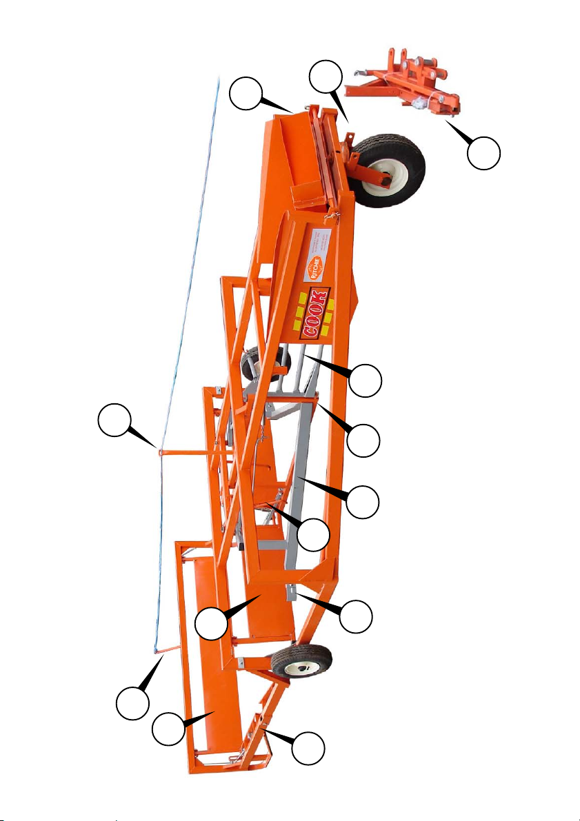
Machine Overview - Model 1422
1
2
3
4
5
Fig 1
7
12
6
8
11
9
13
10
1. Drawbar (in transit packing)
2. Wheel Castor Lugs
3. Chute (in transit position)
4. Transfer Gate
5. Centre Frame
6. Turning Arm (RH)
7. Turning Arm End Deflector
8. Transfer Gate Trip
9. Front Gate
10. Folding Rear Frame
11. Rear Gate
12. Rear Gate Release Lever
13. Rope Guide

Preparation
When despatched from the factory the Bale
Accumulator is partly dismantled to save
space on vehicles, after unpacking assemble
as follows:-
Drawbar and Chute
Remove the chute from the transport
position, Fig 2, by releasing the R-pins at both
ends of the swivel (arrowed) and lifting the
chute out.
Unpack the drawbar and fit the t-bar, Fig 3,
(circled) to the slides on the underside of the
chute. Fig 2
Fig 3
10
Table of contents
Other Ritchie Farm Equipment manuals


