roblight FL 1500 XT User manual

RobLight accepts no responsibility for possible errors in catalogues, brochures and other printed m aterial.
RobLight reserves the right to alter or discontinue its products w ithout notice. © 2019 RobLight A/S
RobLight A/S, Nordhavnsvej 1A, DK-9900 Frederikshavn
T: +45 9244 4888, E: info@ rob-lig h t.c o m
www.rob-lig h t.c o m
99082148, 26-03-2021, Rev. 1.2
User m anual
FL 1500 XT

The RobLight FL 1500 XT light generator is designed for outdoor use, w ith glass and
PM M A fibre harness Ø28 m m . It can be used in all installations set-ups, including
closed com partm ents if lim its for m ax am bient tem perature are follow ed.
FL 1500 XT is designed as replacem ent for FL 150 XT-se rie s.
In t r o d u c t io n
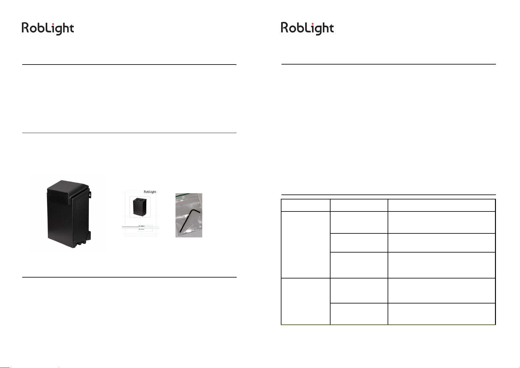
Product overview /unboxing
1 FL 1500 XT
1 U ser m anual
1 Allen key
In s t a lla tio n in s tr u c t io n s
Follow the installation instructions to ensure
· Safe operation
· Full functionality
· Stated expected lifetim e
· Uninterrupted illum ination
Troubleshooting
The effectiveness of the active cooling device is greatly dim inished if the cooling
fin s a n d th e a ir in ta k e is b lo c k e d o r p o llu te d w ith d u st. T h is w ill re d u ce th e e x -
pected lifetim e of the product.
The dust m ust be rem oved on a regular basis. Interval depending on the environ-
ment.
A fine brush, vacuum cleaning or light com pressed air can be used for the cleaning.
This light source is not supposed to be otherw ise serviced, if used as recom m ended.
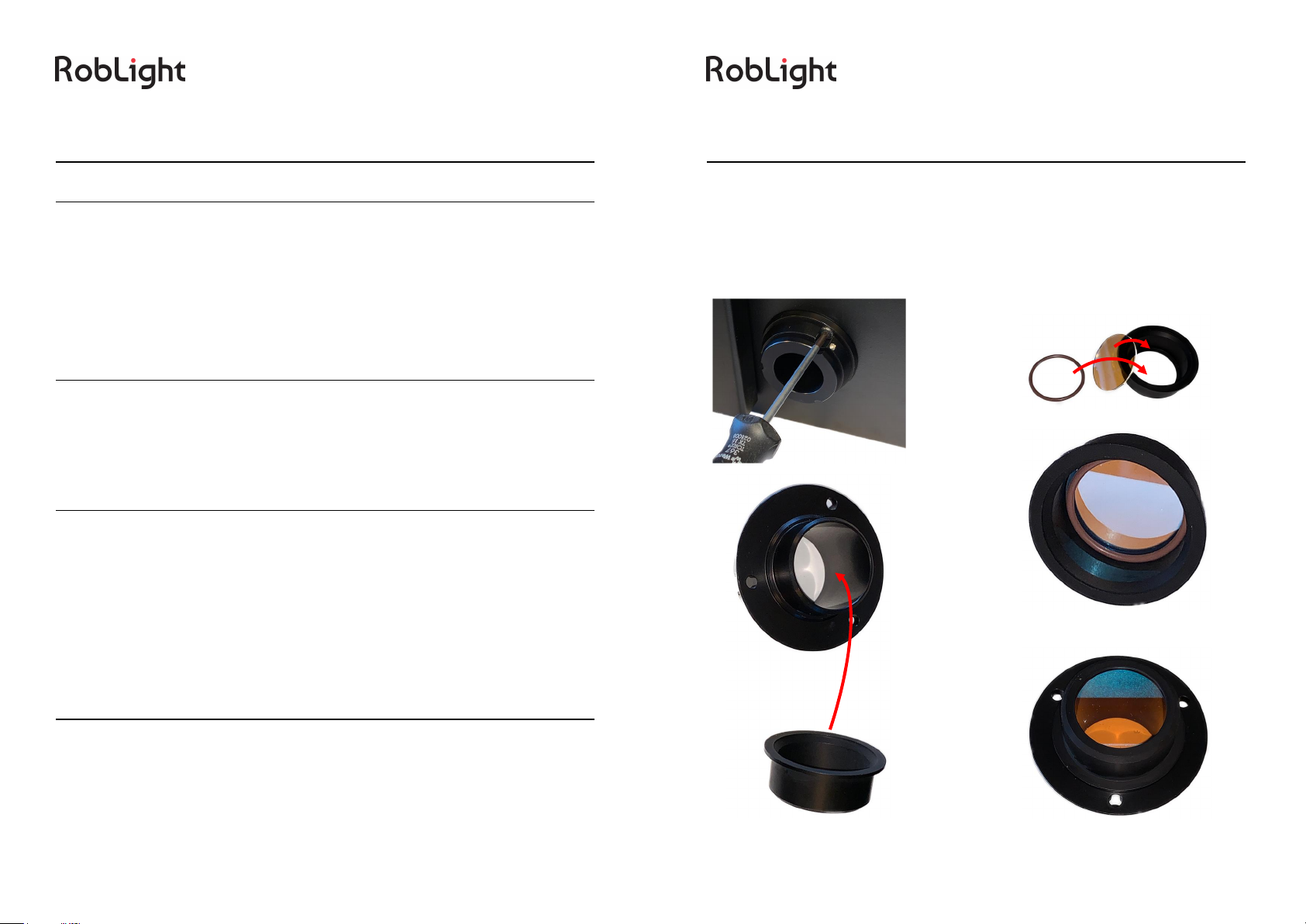
The fan can be replaced using standard tools. A replacem ent kit w ith guide is avail-
able.
If t h e p ro d u c t is n o t p e rfo rm in g a s s p e c ifie d , u se th e t ro u b le sh o o t in g g u id e . If y o u
need further assistance, please contact RobLight.
Maintenance, spare parts and repairs
If p ro b le m s a re n o t s o lv e d u s in g t h is g u id e , p le a s e c o n t a c t R o b L ig h t A / S .
Problem Trace the problem Solution
No light
Check the pow er Connect the pow er cord properly/ Turn
on the device
Check the tem pera-
tu re .
Check it is installed according to the
in stru c tio n s .
Check the dim m ing Unplug. Unplug the dim m er system
fro m th e d riv e r. T u rn o n th e p o w e r.
Light sw itches
on and off
Check the operating
conditions of the
lig h t g e n e ra to r
Check it is installed according to the
in stru c tio n s .
Check active cool-
in g s y s t e m .
Rem ove dirt and dust from light gene-
ra to r.
Problem Trace the problem Solution
No light
Check the pow er Connect the pow er cord properly
Turn on the device
Check the tem pera-
tu re
Check if it is installed according to the
in s tru c t io n s
Check the dim m ing
Unplug the light generator. Unplug the
dim m er system from the driver. Turn
on the pow er
Light sw itches
on and off
Check the operating
conditions of the
lig h t g e n e ra to r
Check if it is installed according to the
in stru c tio n s
Check the active
cooling system
Rem ove dirt and dust from the light
generator

Application notes
The light generator is an electronic device and m ust be handled accordingly. The
different com ponents w ill have different factors influencing the practical lifetim e.
The m ost im portant factor for this system is the condition of the surrounding air
(te m p e ra tu re a n d cle a n lin e ss). T h e d a ta w e h a v e sta te d a b o u t o r a n d th e e xp e c te d
life tim e o f th e k e y c o m p o n e n ts, a re a t th e t e m p e ra tu re s th a t th e su p p lie rs h a v e
perform ed during their standardized tests in clean environm ents.
The light generator is designed to run at m ax am bient tem perature, but the longest
usable operation is achieved w ith low er tem peratures.
Although there is therm al protection built into this device, it is only a safety device
and should not be used as a m easurem ent device to test if the light generator is
ru n n in g a t a to le ra b le su rro u n d in g te m p e ra tu re .
The polyconnector is the m ost stressed part of this system .
Care should be taken to ensure that the fibre ends are 100% clean and free from
dust and grease (fingerprint w ill do dam age.). See w w w .rob-lig h t .c o m fo r re c o m -
mendations to clean fibre ends.
Running the light generator at too high tem peratures w ill not only risk dam age to
th e ligh t so u rce b u t a lso to th e fib re h a rn e ss.
CLEAN AIR
KEEP COOL
This device has a built in high pow er phosphor converted blue led. The light source
is g ro u p e d in R isk G ro u p 2 .
Warning
Do not look into the light port w hen lit.
Bew are of placing highly light absorbing m aterial directly in front (Distance 0-1cm )
of the port or a fibre. The extrem ely high intensity w ill increase the tem perature in
th e m a te rial.
Using non RobLight harnesses in this light generator is at its own risk.
Ensure that the polyconnector is undam aged and clean before using the light gener-
ator in retrofit RobLight installations.
Bew are that w hen the or a light generator is operated at m ax am bient tem perature
th e su rfa ce te m p e ratu re ca n e xce e d 7 5 ° C .
The light generator is only tested w ith RobLight standard polyconnector end.
The w arranty label is not to be broken under ANY circum stances. If broken the
warranty is terminated.
Warranty label
Risk group 2
CAUTION.
Possibly hazardous optical radiation em itted from this
product. Do not stare at operating lam p. M ay be harm ful
to th e e ye .

General
Light port Ø28 m m
Fibre type PM M A or glass
Material Alum inium , POM and other
Dim ensions (L x H x W ) 375 x 170 x 300 m m
Weight (total) 8600 g
Safety CE
Environm ental
Protection rating IP 4 5
Therm al protection In te g ra t e d a u t o
Cooling Axial fan x 2
Am bient tem perature -10° to 45°C
Driver/electrical
Driver In v e n t ro n ic s
Supply voltage (m ains) 100-240V 50/60H z
Driver expected lifetim e 100.000 hours (@ TC = 65°C)
Total pow er consum ption 130 W (C-DMX), 115 W (w hite light)
Fan expected lifetim e 40.000 hours
Fan sound level 30dB (A)
Light source
Applied LED Nichia
LED expected lifetim e >35.000 hours @ Ta = 45°C
Typical CCT 3000K or 4000K (5000K on request)
Typical Ra (CRI
1-8
) 90+
Dim m er system s applicable Pot, DM X depended on the m odel
Technical data
In s t a llin g a c c e s s o r ie s
1. Rem ove the connector (3 screw s)
2. Mount the filtre in the bracket
3. place the filter bracket on the back side of the connector
4. Replace the connector in the light generator
1
2

Accessories / Spare part
Part nam e Description It e m n o .
Adapter Ø28/Ø9
To change the light
port from Ø28 to
Ø9 m m
7800 0130
Fan replacem ent kit Repair kit w ith parts
to in sta ll n e w fa n 0130 8000
Mounting kit Mounting plate for C
and F m odels 0136 9001
DMX control m anual 9908 2152
CTC filter-1000K Ø 28 0126 1019
CTC filter –1200K Ø28 0126 1020
CTC filter –900K Ø28 0126 1021
CTC filter +2000K Ø28 0126 1022
CTC filter +1000K Ø28 0126 1023
FL 1500 XT filter
holder 4900 1530
a) Rem ove cap from the light port
b) Check that the end face of the polyconnector is clean and undam aged
c) In se rt t h e p o ly c o n n e c to r fu lly in th e lig h t p o rt
d) Tighten the screw onto the light port w ith an Allen key
e) Ensure all installation and ventilation requirem ents are m et
f) Connect the supply cord to the m ains
WARNING!
Rem ove cap before
tu rn in g o n .
In s t a lla tio n in s tr u c t io n s

Vertical m ounting XT m odels
This light generator should not be m ounted w ith light port upw ards. At high am bi-
ent tem perature the operational lifetim e of the internal com ponents and harness
will be reduced.
Mounting
Attach to surface using three screw s in the baseplate holes.
Be aw are that the total w eight of this system is m ore than 8.6 kg + the dow nforce
fro m th e fib re h a rn e ss.
1
2
Drill 3 x Ø6 mm holes.
270 mm
270 mm
MAX AMBIENT TEMPERATURE 45°C.
Recom m endations: (should alw ays be tested in a m ock up)
Secure enough space to allow natural heat transm ission through surfaces.
Surfaces should not be insulated.
Cooling air for the polyconnector can not be obstructed in any w ay, as it is essential
to avo id d am a ge to th e h a rn e ss.
General m inim um distance from the light generator to any enclosing surface 15 cm
(e x c lu d e d m o u n tin g su rfa c e ).
Bew are of inlet and outlet ventilation holes
opposite each other as show n on the draw ing.
Keep free from dust and polluted air.
In s t a llin g a d ja c e n t lig h t g e n e r a t o r s
Recom m endation:
Minim um 30 cm distance between adjacent light generators to ensure enough free
cooling air.
If m u ltip le r o w s , u se o ffse t t o a v o id v e rtic a l r o w s . M in im a l f re e d is t a n c e b e tw e e n
ro w s 4 0 c m .
Max tem perature has to be observed for all light generators m easured at air inlet
fo r e a ch lig h t g e n e ra to r.
MAX AMBIENT TEMPERATURE 45°C.
30 CM
Closed com partm ents
Table of contents
Other roblight Lighting Equipment manuals
Popular Lighting Equipment manuals by other brands

Awex
Awex EDGE S Assembly instructions

PacLights
PacLights FALC Series installation guide

GM Lighting
GM Lighting LEDTask LTR-S Series manual

Ikan
Ikan LB10-2PT-KIT quick start guide

LightwaveRF
LightwaveRF Connect JSJS LW550 Operation manual

GAME OF BRICKS
GAME OF BRICKS Optimus Prime 10302 instruction manual