manuals.online logo
Brands
  1. Home
  2. •
  3. Brands
  4. •
  5. Rockler
  6. •
  7. Tools
  8. •
  9. Rockler 22818 User manual

Rockler 22818 User manual

Introduction
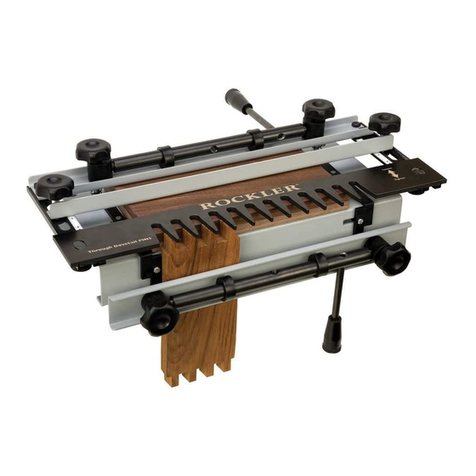
Your new dovetail jig will cut Full Through
Dovetails and three varieties of Half Blind
Dovetails (flush half blind, offset half blind
and rabbeted half blind). (Figure 1) It will
accommodate stock from 1/2" to 11⁄8" thick
and up to 11" wide.
The following instructions begin by detail-
ing how to set up the jig for basic 1/2"
and 3/4" material to mill flush half-blind
dovetails and full through dovetails (Fig. 1).
Once you have mastered this technique, you
can add other joints to your repertoire such
as offset dovetails and rabbeted dovetails.
(See page 8 for details.)
Square and flat material is key to the success of
perfectly aligned joints. For any of the joints being
cut, always cut additional pieces the exact size of
those being used in your project to experiment with
the settings for joint accuracy
1 Clamp Handle (2)
2 Cam (4)
3 Clamp Axle (2)
4 Stop Bar (1)
5 Clamp Bar (2)
6 Pin Template
7 Clamp Springs (not shown)
8 Fence Lock Knobs (2)
9 1/2" Half-Blind/Tails Template (1)
10 Jig Body (1)
PARTS LIST - Complete Dovetail Jig
160
5405 & 160
5405 & 160
5405 & 160
5405 & 160
5405
Blk
Cyan & Blk
160, (white rockler)
5405, (white rockler)
Preferred
5405 & 160
Black
5405
647
Black
5405
Complete Dovetail Jig Instructions
Through Dovetails Half Blind Dovetails
Figure 1
1
11 “L” Shaped Adjustable Stops (2)
12 Cam Lock Knob (4)
13 Cam Lock Housing (4)
14 Template Adjustment Bar (2)
15 1/2"-14° Dovetail Bit
16 1/2"-8° Dovetail Bit
17 5/16" Straight Bit
18 1/2"-8mm Collet Reducer
19 Template Guide Bushing Set
5
9
2
10
11
9
14
19 17 16
15
18
43
112
13 8
6
Secure the Jig
Two holes in the bottom of the jig allow permanent attachment to a work-
bench or similar stable base. Where work space is limited, the same holes
allow mounting to a shop-built movable base (Fig. 2) that can be secured in
the jaws of a vise. The jig can then be stored elsewhere when not in use.
The base is just two pieces of sheet stock (plywood, MDF, melamine, etc.)
screwed together at 90°. An optional glued dado strengthens the joint and
provides extra stability.
Set Up the Router
Included with your jig are a 1/2"-14º dovetail bit for half blind dovetails,
1/2"- 8º dovetail bit and 5/16" straight bit for full through dovetail joints. Also
included is a 1/2"-8mm reducer for your 1/2" router collet. The 8mm shank
size will significantly reduce the amount of chatter and offer a cleaner cut.
Also included is a 7/16" guide bushing assembly. The bushing is universal:
it fits most popular brands of routers and after-market bases. (In the remote
chance that you have difficulty attaining a perfect fit, consult your router’s
manufacturer; they usually offer a guide bushing as an option.)
HALF-BLIND INSTRUCTIONS
Drawer Layout
It is recommended that you keep track of the parts of each drawer by
numbering and labeling them, then milling them in the same order every
time you build a drawer or box. This repetition will virtually eliminate
mistakes, with practice.
Refer to the drawing above to see how this is done. The parts of the drawer
are laid out in their proper orientation, then each piece is labeled on the
inside face (FRONT, BACK, LEFT SIDE, RIGHT SIDE). You can write
directly on the part with a soft pencil, or use masking tape.
Mark the faces next: each face should have a notation that says which way
is up. Finally, mark the corners with designated number, 1 through 4. For
example, the left side of the drawer in the illustration meets the front at
corner #1, so each part is so labeled. If you can develop a habit of marking
the drawers in exactly the same fashion every time, errors will be few and
far between.
Install the bushing in the router base and secure it with the included
threaded ring. Tighten the ring securely, then slide the base toward the
motor housing and install the bit.
For half blind dovetail joints you will be using the 1/2" x 14º dovetail bit.
Depth of cut will be 9/16" from the base of your router. Included on the half
blind template is a gauge for setting this height (Fig. 3). Adjusting for joint
tightness will be covered later in these instructions.
A shop-built base
allows for quick setup
in the workbench vise,
and easy storage.
Figure 2
13
3
12 2
4 4
FRONT
BACK
LEFT
RIGHT
14
Left side up
2
Figure 3
Locate the Stops
The jig is equipped with two stops (Fig. 4) that locate the drawer parts and allow
repetitive milling; once they are set you can build as many drawers as you need.
The first step is to to ensure that the dovetails are evenly spaced on your work
piece (that is, there is the same amount of pin or tail top and bottom). With the
half blind (straight fingers) template installed, slide a piece of scrap the same
width as your drawer stock into the jig. Center the board (left and right) on the
template fingers, as shown in Figure 5. The idea is to have the same amount of
finger or gap showing at each side of the board. Make sure the board lies at 90°
to the front of the jig, then loosen the three screws in the adjustable stop (the left
one, Part 11, see (Fig. 6), and slide it snug against the board. Tighten the three
screws. Repeat this process for the right side of the jig.
Insert the Drawer Parts
During initial set-up adjustment, always use test pieces the same thickness and
width as your drawer sides that you will be milling. Only install the actual drawer
sides after you’ve produced a satisfactory joint in the test pieces. Figures 6, 7
and 8 illustrate the process involved in installing the two boards for each joint.
Note that the two left-hand joints (that is, the joints that attach the left drawer
side to the drawer front and back) are cut at the left side of the jig. Subsequently,
the two right-hand joints will be milled at the right-hand side of the jig.
Shop Tip: Always position drawer parts so inside is facing out.
Begin by installing the drawer’s left side in the front of the jig (vertically), and
securing it with the cam lock. You may have to adjust the cam lock for a good fit;
don’t over-tighten it. The top edge of the work piece should protrude above the
jig body (Fig. 6), but perfect alignment isn’t necessary at this time.
Shop Tip: For even clamping, always use scrap wood the same thickness as
your stock as support on the opposite end of the jig.
Slide the drawer front into the top of the jig (horizontally). The inside face of this
part should be facing up.
Butt the drawer front tightly against the drawer side (Fig. 7), check that it is tight
against the stop (Part 11), and secure it in place with the cam lock.
Now you can slide the drawer side up so that its top edge is flush with the top
face of the drawer front as shown (Fig. 8). Secure the drawer side in place, tight
against the stop (Part 11), by engaging the front cam lock.
Figure 4
Figure 6
Support
scrap
Figure 7 Figure 8
Equal distance
Figure 5
3
Set the Template
For 1/2" material, set the back edge of the half blind template to the “A” setting
(Fig. 9) on the adjustment arm. For 3/4" thick material use the “B” setting (Fig. 9).
All the template settings for 1/2" and 3/4" material are designed as starting
points to rout your joints. Depending on material thickness, tolerances in the
guide bushings and router bits, the template may need minor adjusting to give
you the desired final fit.
Set the Stop Bar
The last adjustment to make before milling begins is to set the Stop Bar (Part 4).
Two knobs (Parts 8) lock the Stop Bar in place.
The reason you set the Stop Bar is that the router base butts up against it at
the end of every cut. This limits the length of the grooves between the pins into
which the tails fit. Note the different lengths of the grooves (Figures 10 and 11).
Both of these settings are for Porter-Cable (53⁄4") base dimensions.
If you are using a router with a base that’s not 53⁄4" diameter, you need to use
the following formula for setting the fence. Setting the fence location sounds
complicated, but it’s really quite simple. You’ll need a piece of paper and a
pencil to work out the location, since you’ll need to add a couple of numbers
together.
Start by writing down a measurement that is twice the thickness of the drawer
side stock (for example, with 3/4" thick sides, this would be 11⁄2"). Now find the
radius of your router base: that is, the distance from the center of the bit to the
edge of the base. Add this to the first number. For example, if your router has a
6" base, you would now have 3" plus 11⁄2" for a total of 41⁄2". The last calculation
is to deduct half the thickness of the bit. The supplied bit is 1/2", so just subtract
1/4". Locate the fence this distance from the front of the template. In our
example, the fence would be 41⁄4" back from the front edge of the template.
Be sure that the fence is set parallel to the front of the template. Secure the
fence by locking down the two knobs, and you’re ready to mill the test boards.
Figure 9
Figure 10
Figure 11
4
Example: 1/2" material using
53⁄4" Porter-Cable router base
with a 1/2” dovetail cutter
1"+27⁄8"=37⁄8"-1/4"=35⁄8"
Making Minor Adjustments
Install your test boards in the jig, set the fence and template to their
correct locations, and then lock the boards in place with the two cam
locks. With the router bit set at the correct height, visually check that
the bit won’t engage the template or any part of the jig. Begin cutting
from left to right, making sure that the bushing rides the template all
the way to the back of each groove. DO NOT LIFT THE ROUTER
OFF THE TEMPLATE WHILE THE MOTOR IS RUNNING. If you do,
the bit will destroy your template.
If the resulting joint is too sloppy, raise the bit 1/64” and try again.
Conversely, if the fit is too tight, lower the bit. Make adjustments in
approximately 1/64" increments, as a small adjustment can make
a lot of difference (Fig. 12).
If the two parts fit together well, but the tails are proud, move the stop
bar back the amount the tails are proud. If the tails slide too far into
the grooves (also called “sockets”) between the pins, move the stop
bar forward the amount they are shy (Fig. 13).
If you don’t have an even amount of pin or tail at the top and
bottom of the drawer, revisit the section entitled “Locate the Stops.”
Sometimes you may want to have a full pin at the top and a half pin
at the bottom. This is easily accomplished by visually adjusting the
stops in the manner described in that section.
Continue milling test pieces (both left and right) until you achieve
results that are satisfactory. Only then should you mill actual work
pieces. The scales on the jig are designed so that when you achieve
the joint you desire you can make pencil marks on them for use later
on for quicker set up (Fig. 14).
FULL THROUGH INSTRUCTIONS
Drawer or Box Layout and Identification of Pins and Tails
Layout all four pieces of your box or drawers and identify which will
be the drawer sides (tail boards) and drawer fronts and backs (pin
boards).
For jewelry or other decorative boxes, you’ll want to display the more
decorative dovetail tails on the front of the box. To do this, label the
front and back pieces as tail pieces as shown at right.
Mark the tail boards and pin boards with a “T” or “P” on the inside
faces.
NOTE: This is a very important step, since the face will either face
towards the operator or towards the jig and will automatically align
all four parts when assembling.
1/4"
1/8"
3/8"
1/16"
3/16"
11/4"
11/8"11/16"
13/16"
1/2"
Heighten to tighten
Figure 12
Figure 13
Figure 14
Router Base
Heighten/tighten,
lower/loosen...
Left
side
T
Back
P
Front
P
Right
side
T
Left
side
P
Back
T
Front
T
Right
side
P
Mark all pieces
on the inside face
Drawers
Boxes
For Drawers
Drawer front:
Pin piece is in front
Drawer
Front
“P”
For Boxes
Box front:
Tail piece is in front
Box
Front
“T”
5
Tails sunken below surface;
move fence forward
Tails proud of surface;
move fence backward
Set up the Jig
When cutting full through dovetails you will be cutting to a depth of
slightly more than the thickness of the material you are working with, so
you will need to cut a clamping shim approximately 10" wide x 7" deep
that’s 1/4" thicker than your stock. An easy way to get this extra thick-
ness is to first cut the shim from your stock material, and then cut a sec-
ond shim piece from 1/4" thick masonite or other 1/4" material (Fig. 15).
Now simply stack the two shims to get the thickness you need. The
shim should be flush with the back edge of the jig body (Fig. 15).
To correctly space the dovetails on the width of your stock, hold your
work piece vertically in the jig as shown in (Fig. 16). Adjust left side stop
(#11) side to side until the fingers on the template are equally spaced on
both edges of your stock.
Then remove the stock and template and use a small square to make
sure the vertical leg of the stop (#11) is square with the top of the jig
body as shown in Figure 18. Tighten all three screws on the L-shaped
stop (#11) and reinstall template.
Cutting the Tail Pieces
You will be using the half blind or tail piece template first. The first step
is to cut a scrap piece the same size as your stock to verify the outer
tails on both ends are the same width. If needed, readjust the L-shaped
stops (#11) to equalize the outer tails (Fig. 16).
Lock the first tail piece vertically (inside face out, marked “T”) in the jig,
flush against the left side stop and tight against the template. Check the
position of the template to verify the fingers extend beyond the face of
the work piece. For 1/2" material, set the back edge of the tail template
to the “B” setting and for 3/4" stock use the “E” setting (Fig. 17). Install
the 7/16" guide bushing provided with your original half blind dovetail jig
on your router.
Now install the 1/2" x 8° dovetail bit provided with the jig.
Next, set the depth of cut to equal the thickness of the stock for the
pin piece. The easiest way to do this is to scribe a line on the tail piece
using the pin piece as a guide (Fig. 19). Set the depth of cut on the
dovetail bit so it will just cut through the scribe line (Fig. 20). This setting
will allow your tails and pins to protrude slightly so they can be easily
planed or sanded flush after assembly. If a dust collector is installed you
will need to do this setting by turning your router upside down and using
the stock you are working with and one of the templates as a guide to
set the depth of cut.
Figure 16
Figure 18 Figure 19
6
Shim
Masonite
Box or
drawer
material
Flush with
back edge
of jig body
Flush with
back edge
of jig body
Figure C Inset
Figure 15
Figure 20
Figure 17
Set the router on the template, making sure the cutter is not in
contact with the template or the stock. Turn the router on and
start cutting on the left edge of the work piece. Keeping the
guide bushing tight against the template, cut the tail by plung-
ing in on the left edge, across the back side and coming back
out on the right side of the tail. Always keep the guide bush-
ing tight against the template fingers, and guide the router in a
clockwise rotation around the tail (Fig. 21).
Flip the piece end for end, keeping the inside face toward the
operator and continue cutting the remaining tails using the
same procedure. Cut all remaining tailboards in the same way.
WARNING: Do not lift the router off the template while the
motor is running. If you do, the bit may ruin your template.
Cutting the Pin Pieces
Cutting the pins determines how tight your joint will be. To
get the jig set up correctly, use a test board exactly the same
dimension as the pin boards used in the project. All pin boards
are cut with the inside face (marked “P”) towards the jig.
Remove the 1/2", 8º dovetail bit and install the 5/16" straight
bit. Remove the tail template and install the pin template. Set
the back edge of the template to the “F” setting (Fig. 22) for
both 1/2" and 3/4" material.
Set the depth of cut the same way as you did cutting the
tailpieces, but this time use the tail stock to scribe your line.
Proceed to cut the joint in the same fashion as you did
the tail boards.
Test Fit
Test fit the pin board to the tail board. If the joint is too tight,
you will need to loosen the two T-bolt knobs and move the tem-
plate away from you approximately 1/16". NOTE: Moving the
template towards you will give you a tighter joint; moving the
template away from you will loosen the joint (as indicated on
the template). Be sure the front edge of the template remains
parallel with the front of the jig body.
Cut off the previously routed pins, and reinstall the same test
piece again, keeping it tight against the left side stop. Then
re-cut the pin test piece.
Follow this process until you produce an acceptable fit.
Proceed to cut all pin boards. Remember to always have the
inside face toward the jig when cutting the pins.
Figure 21
Figure 22
7
Some other joints you can make with
your Rockler 12" Dovetail Jig
Offset Dovetails (top drawing) can be used when there
is no separate drawer face to attach to the drawer front.
They give you an integrated overlay; that is, part of the
drawer front overlays the face frame of the chest or
cabinet. To mill the joint, just add 3/4" to the length of the
front. The part thickness should be a minimum 7/8" thick,
and the rabbet on each end should be milled before
inserting the piece in the dovetail jig. Move the backstop
3/8" back, and test your setup on scrap.
Rabbeted Dovetails (middle drawing) add a lip to the
top, bottom and sides of the drawer front. They are
milled in the same fashion as the offset dovetail (above),
except that you must reset the right and left stops for the
drawer front. Note: You’ll need to shim the horizontal/top
arm of the “L-shaped” stop 3/8" so that the offset is 1/8"
instead of the standard 1/2", then proceed.
Tool Safety Rules
1. Keep your work area clean
and well lighted.
2. Do not use a router with this
jig when tired or under the
influence of drugs, alcohol
or medication.
3. Avoid loose clothing or
jewelry.
4. Unplug the router to make
any adjustments.
5. Remove the wrench(es)
before starting the router.
6. Always wear eye, dust, and
hearing protection.
7. NEVER lift the router off
the jig while the bit is still
spinning.
8. Secure the jig to a solid
base (such as a heavy
workbench) before using.
9. Keep children and other
distractions away.
10.Always replace damaged
parts before using the jig.
© Rockler Companies Inc. 2007
8
160
5405 & 160
5405 & 160
5405 & 160
5405 & 160
5405
Blk
Cyan & Blk
160, (white rockler)
5405, (white rockler)
Preferred
5405 & 160
Black
5405
647
Black
5405
Quick Guide for Half Blind Joints
on 1/2" material
1. Set router bit (1/2"-14°) depth to 9/16"
using guide on half blind template.
2. Adjust side stops for equal spacing of
dovetails.
3. Install both vertical and horizontal pieces
tight up against side stops.
4. Set back of template to
“A” setting on scale.
5. Set stop bar to “C” setting.
6. Rout joint.
7. Adjust settings as needed.
8. Document final settings
on scale for future use.
Quick Guide for Through Joints
on 1/2" material
1. Set router bit (1/2"-8°) depth to material
thickness plus template thickness.
2. Adjust side stops for equal
spacing of dovetails.
3. Install tail piece vertically into jig
and clamp securely.
4. Set back of tail template to
“B” setting on scale.
5. Route both tail boards.
6. Install 5/16" straight bit.
7. Set depth to the same as dovetail bit.
8. Install pin piece vertically into jig and clamp
securely.
9. Set back of pin template to “F” setting.
10. Rout pins, remove from jig and test fit
with tail pieces.
11. Adjust if needed and document
settings on scales.

This manual suits for next models

1

Other Rockler Tools manuals

Rockler JIG IT User manual

Rockler

Rockler JIG IT User manual

Rockler 22.5 Miter Sled User manual

Rockler

Rockler 22.5 Miter Sled User manual

Rockler ProFence 47905 User manual

Rockler

Rockler ProFence 47905 User manual

Rockler 57550 User manual

Rockler

Rockler 57550 User manual

Rockler 37375 User manual

Rockler

Rockler 37375 User manual

Rockler 59133 User manual

Rockler

Rockler 59133 User manual

Rockler 63779 User manual

Rockler

Rockler 63779 User manual

Rockler 53418 User manual

Rockler

Rockler 53418 User manual

Rockler JIG IT 50713 User manual

Rockler

Rockler JIG IT 50713 User manual

Rockler 57302 User manual

Rockler

Rockler 57302 User manual

Rockler JIG IT User manual

Rockler

Rockler JIG IT User manual

Rockler Indexing Dado User manual

Rockler

Rockler Indexing Dado User manual

Rockler 52149 User manual

Rockler

Rockler 52149 User manual

Rockler Beadlock Pro User manual

Rockler

Rockler Beadlock Pro User manual

Rockler Interlock Signmaker’s Templates State Park User manual

Rockler

Rockler Interlock Signmaker’s Templates State Park User manual

Rockler 55512 User manual

Rockler

Rockler 55512 User manual

Rockler Trim Router Table User manual

Rockler

Rockler Trim Router Table User manual

Rockler GRP40589 User manual

Rockler

Rockler GRP40589 User manual

Rockler 53651 User manual

Rockler

Rockler 53651 User manual

Rockler Miter-Tight Picture Frame Clamp User manual

Rockler

Rockler Miter-Tight Picture Frame Clamp User manual

Rockler Dust RIGHT User manual

Rockler

Rockler Dust RIGHT User manual

Rockler HPL Installation guide

Rockler

Rockler HPL Installation guide

Rockler Dust Right 52542 User manual

Rockler

Rockler Dust Right 52542 User manual

Rockler 45968 Operating instructions

Rockler

Rockler 45968 Operating instructions

Popular Tools manuals by other brands

Storch 360735 manual

Storch

Storch 360735 manual

PCB Piezotronics GK291D Installation and operating manual

PCB Piezotronics

PCB Piezotronics GK291D Installation and operating manual

Hainbuch SPANNTOP NOVA installation manual

Hainbuch

Hainbuch SPANNTOP NOVA installation manual

AEG FUSION ADT18 manual

AEG

AEG FUSION ADT18 manual

jbc PA120-A instruction manual

jbc

jbc PA120-A instruction manual

HOZAN C-702-13 instruction manual

HOZAN

HOZAN C-702-13 instruction manual

BGS technic 6929 manual

BGS technic

BGS technic 6929 manual

Viessmann 4198 H0 Operation manual

Viessmann

Viessmann 4198 H0 Operation manual

RED ROOSTER RRI-14 manual

RED ROOSTER

RED ROOSTER RRI-14 manual

Pittsburgh Automotive 59677 Owner's manual & safety instructions

Pittsburgh Automotive

Pittsburgh Automotive 59677 Owner's manual & safety instructions

ReelCraft 7000 Series operating instructions

ReelCraft

ReelCraft 7000 Series operating instructions

STEPCRAFT MM-1000 Operating/safety instructions

STEPCRAFT

STEPCRAFT MM-1000 Operating/safety instructions

Powerfix PMT 1.1 A1 original operation manual

Powerfix

Powerfix PMT 1.1 A1 original operation manual

General Pump D30001 Operator's manual

General Pump

General Pump D30001 Operator's manual

CTS VGM Use and maintenance manual

CTS

CTS VGM Use and maintenance manual

VEVOR 3 IN 1/305 Operation manual

VEVOR

VEVOR 3 IN 1/305 Operation manual

Junkers JU-87D Stuka instruction manual

Junkers

Junkers JU-87D Stuka instruction manual

Kreg KHI-PULL-INT owner's manual

Kreg

Kreg KHI-PULL-INT owner's manual

manuals.online logo
manuals.online logoBrands
  • About & Mission
  • Contact us
  • Privacy Policy
  • Terms and Conditions

Copyright 2025 Manuals.Online. All Rights Reserved.