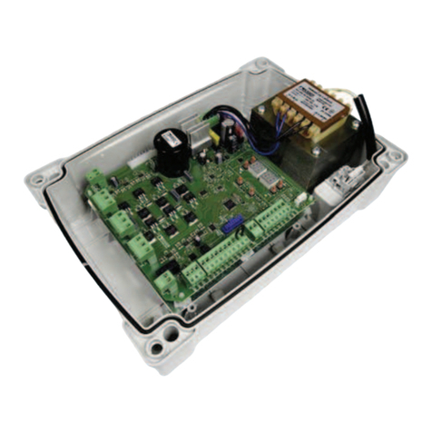
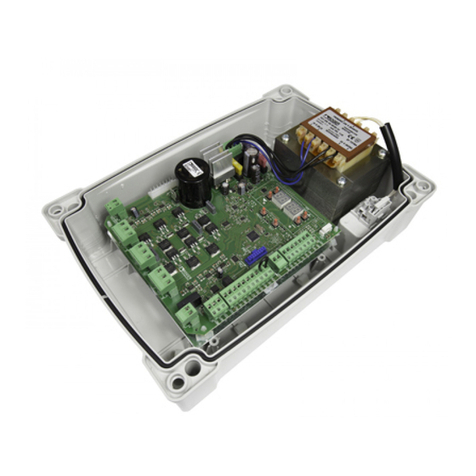
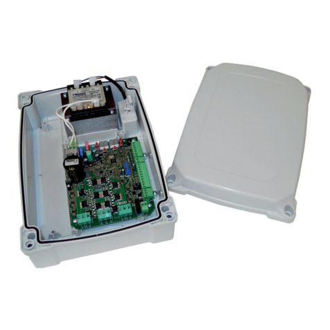
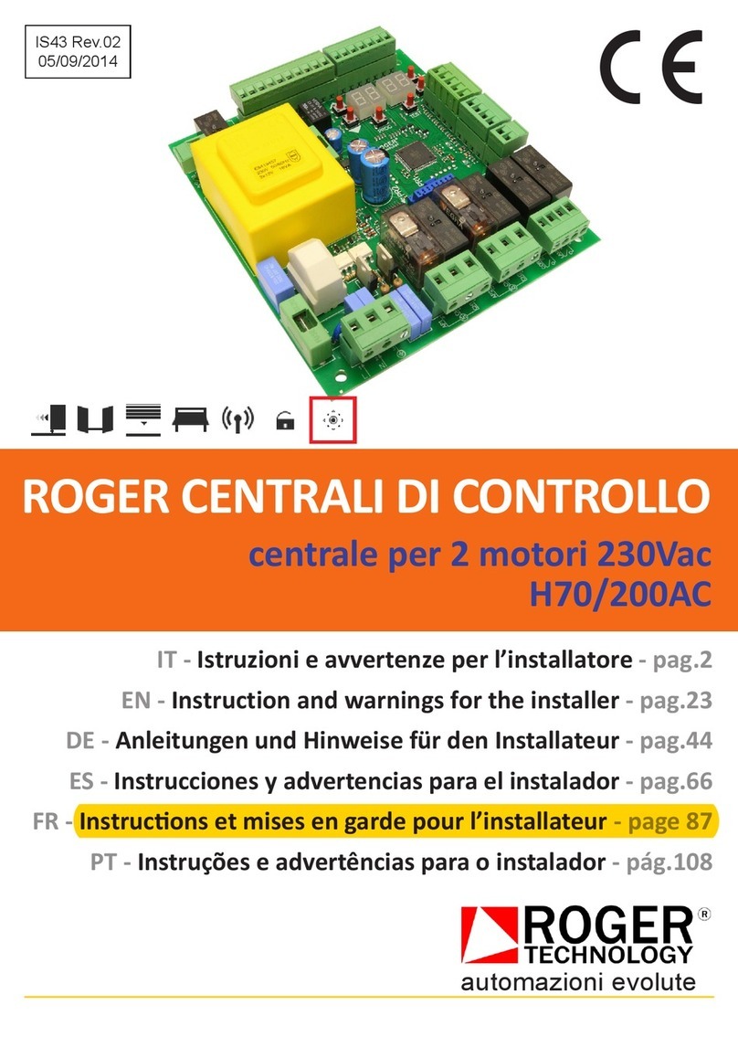
Roger H70/103AC User manual

IS36 Rev.02
21/07/2011
CENTRALE DI COMANDO - CONTROL UNIT H70/103AC
ISTRUZIONI E AVVERTENZE PER L’INSTALLATORE
INSTRUCTIONS AND RECOMENDATIONS FOR THE INSTALLER
INSTRUCÇÕES E ADVERTÊNCIAS PARA A INSTALAÇÃO
ISTRUCTIONS ET AVERTISSEMENT POUR L’INSTALLATEUR
1
H70/103AC

TECHNICAL DETAILS
1 motor 230V~ ±10% 50Hz, 2200W max
Working temperat re from -10 to +55°C
Flashing light 1A max (tension free contact )
Co rtesy 2A max (tension free contact)
Open gate led 24Vcc 2W max
Accessories c rrent 300mA max on 24Vcc
2 levels of slow-down speed
8 levels of start p torq e
8 levels of normal torq e on travel
8 levels of force on slow-down
Electronic stop with 8 levels of stopping torq e
99 sensibility levels to find an obstacle on normal
speed
99 sensibility levels to find an obstacle on slow-down
speed
Software selection on right or left motor
Software excl sion of inp t N.C. not sed
Config rable inp t clock
2 inp ts for safety edge
1° radio channel sed for different inp t/o tp t
2° radio channel sed for different inp t/o tp t
Flashing light o tp t free of tension
Co rtesy light o tp t free of tension
Travel checking by encoder and limit switch
A tomatically learning of the travel
Works witho t limit switch (it is necessary encoder)
5 modes of inp t f nctioning of step by step
Password to protect the config ration
Memorized of n° of movement
Memorized working time of the motor
Memorized working time of control nit
Showed serial n mber of control nit
CONFIGURATION OF THE PARAMETERS
The config ration of the control nit is made changements on the
predefinied val e associated on the parameter thro gh 3 b ttons,
S1, S2 e S3, and it showed on the dispaly (pict re 1). The control
nit is s pplied with defa lt val e, please look on last col mns on
the attached parameters table.
STANDBY MODE
After 10 min tes witho t any p shing, display comes on standby, and it shows Yo only the POWER segment with
intermittent light (pict re 5).
SHOWING INPUT MODE
When the power comes back, or p shing one of the 3 b ttons, the display will show Yo the inp ts state.
From each inp t of the control nit is associated a segment on display (pict re 5). If the inp t is closed the segment
is on, if the inp t is open the segment is off, if the inp t is not enable (short circ ited) on software the segment
flashing
The 2 radio channels can be associated to different comands (parameters 76 e 77), when we activate one of the
radio channel the control nit will show Yo the referent segment.
SHOWING PARAMETERS MODE
When we p sh the b ttons S1 or S2, the control nit changes from inp t showing to parameters showing (pict re
2).
The parameter is showed on the first two n mbers on the left of the display by intermittent light, while the val e of
the parameter is showed on the right of the display by fixed light.
When we p sh the b tton S2 the control nit shows Yo the next parameter and his val e from the first to the last.
By the parameter LL=0 the control nit shows Yo only the basic parameter, while by LL=1 the control nit shows
Yo all the parameters.
When we achieve the last parameter (CP), another p shing of the b tton S2 the control nit will show Yo the inp t
showing, and if we p sh again the b tton the control nit will show Yo the parameters showing yet. By the b tton
S1 we have the same f nctions b t in the opposite way, from the last to the first.
10
INPUT LL 02 03 ... P4 CP
S2 S2 S2 S2 S2
S2
INPUT LL 02 03 ... P4 CP
S1 S1 S1 S1 S1 S1
S1
SELECTION BUTTON SCROLLING BUTTON
S3 S2 +
PARAMETER NUMBER PARAMETER VALUE
S1 -
Pict re 1
S2
Pict re 2
GB

PARAMETER CHANGE MODE
If we select the parameter to be modified, p shing the b tton S3 we can modified the parameter. If the control nit
is protected by password, the parameter co ld be only showed b t not modified, we can modified the parameter if
we enter the password (P1,P2,P3,P4).
The parameter is showed on the first two n mbers on the left of the display by fixed light, while the parameter val e
that we can modify is showed on two n mbers on the right of the display by flashing light.
We can modify the val e of the parameter by the b ttons S1 and S2, we can choice one of the val e indicated (look
the parameter table indicated).
If we p sh the b tton S3 we confirm the selection and we come back on the parameter showing mode.
If we are on parameter modifing mode and we do not p sh any b tton, after 30 sec. the control nit a tomatically
comes back on parameter showing mode.
When we change the parameter val e, these changements are a tomatically done if the gate ses the closing limit
switch (totaly close), otherwise Yo have to power off and after Yo have to power on.
STANDARD INSTALLATION
Yo have to make the electric connections of the accessories, of the
comands and of the safety elements (pic. 4).
Make attention when Yo connect the flashing light and the co rtesy
beca se they are on tension free contact (pic. 3).
Make the power connection.
It is not necessary to make short circ it to any safety inp ts that we do not
se, like LIMIT SWITCH (parameter 72), PHOTOCELLS (parameters 50, 51,
53 and 54) and SAFETY EDGE (parameters 73 and 74), beca se it can get
off by software(the corrisponding segment will flash on inp t showing). Yo
have to short circ it only to the STOP parameter, if Yo do not se it.
Use the parameter n mber 71 to choice the side of the motor: right or left (look it on the internal). The standard
option is on right side (71 = 1), if the motor is installed on left side 71 = 0. When Yo make this changement Yo
have to power off and after Yo have to power on.
It is necessary to make the learning of the travel lenght: Yo have to man ally fit the gate on intermediate
position, after Yo have to select the parameter n mber 10, set the val e to 1 and Yo have to confirm it by S3,
after we see flashing all n mbers and p sh the PP. The motor will make a complete opening and closing in
slow-down, if the process is made in right mode, the parameter comes back to 0. If the display show Yo . If the
display shows Yo _E, it means that the process is failed, and Yo have to repeat it; If the process failed again,
Yo have to increase the torq e (parameter 32), or decrease the sensibility (parameter 43) and repeat the
learning.
REFERENCES CONTROL STATUS
The control nit is on references control stat s in 3 cases:
mechanical release opening and man al movement;
after black-o t
when the limit switch is not installed and the gate finds an obstacle for three contin ation times in the same
place. In this case the control nit waits for a comand of the installer, when the control nit receives it opens in
slow-down ntil to mechanical stop or limit switch, when the control nit receives another comand it closes in
slow-down ntil to mechanical stop or limit switch. If the process is made in the right way the control nit comes
back to normal f nctionning, otherwise it contin es to slow-down movements ntil one of the references has
been verified.
PASSWORD
There is the possibility to select a password, composed by 4 parameters P1, P2, P3 e P4. If in the 4 parameters we
do not select the n mbers corrisponding to the password, it is not possible to modified all the other parameters, we
can only view them.
The password settled by s is 00 00 00 00, so the control nit is deblocked.
To change the password it is necessary deblock the control nit p shing in the 4 parameters P1, P2, P3 e P4 the
old password, after we have to insert the n mbers of the new one, we select the paramenter CP, we p sh the
b tton S3 (00 flashing) e finally we have to p sh together the b ttons S1 and S2.
When the control nit is deblocked, to block it again Yo have to power off or waiting the stand-by of the display (it
showes only the POWER led flashing).
11
COR LAM F N
Pict re 3
COURTESY FLASHING LIGHT

Parameter
N mber
Desc iption of pa amete function
parameter val e → Behavio r of the parameter
Defa lt Val e
INPUT Showing of input status (pict re 5)
LL Configu ation level
0 → BASIC shows Yo only a part of the parameters (ones not marked by A)
1 → ADVANCED shows Yo all parameters
0
02 Automatic closing afte pause time
0 → OFF not a tomatic closing
1-15 → n mers of reclosing chance
99 → it always reclosing
0
03 Automatic closing afte blackout
0 → OFF it does not close when the power comes back
1 → ON it closes when the power comes back
0
04 STEP BY STEP (PP)
0 → OPEN – STOP – CLOSE – STOP – OPEN - STOP
1 → PP CONDOMINIUM, when it is completely opens, it renews pa se time
2 → PP CONDOMINIUM, when it is completely opens, it closes
3 → OPEN – CLOSE – OPEN - CLOSE
4 → OPEN – CLOSE – STOP – OPEN - CLOSE
0
05
A
P eflashing
0 → flashing light start to flash when the gate moves
1-60 → SECOND anticipate time of preflashing before the gate moves
99 → in opening not enables, 5 seconds preflashing in closing
0
06
A
PP Condominium Pedest ian
0 → pedestrian makes: OPEN – STOP – CLOSE – STOP – OPEN - STOP
1 → pedestrian always open
0
07
A
Deadman
0 → normal f nction
1 → the gate moves only if Yo press the b tton OPEN and CLOSE
0
08
A
Open gate led (SC)
0 → when the gate is closed the led is switch off, otherwise the led is fixed on
1 → slow flashing in opening, fast in closing and fixed when the gate is completely open, do ble flashing
when the gate stopped in the middle of the travel
0
10 Length t avel lea ning (Yo have to do that when the gate is in the middle of his travel)
To make the travel lenght learning Yo have to set the val e to 1 and Yo have to confirm it by S3, after we
see flashing all n mbers and p sh the PP. The motor will make a complete opening and closing in slow-
down, if the process is made in right mode, the parameter comes back to 0. If the display shows Yo _E, it
means that the process is failed, and Yo have to repeat it
0
11
A
Slow-down t avel
1-20 → PERCENTAGE of slow-down travel respect of normal speed
10
13
A
Tolle ance of the position in which the gate it is conside closed
1-99 → MILLESIMUM respect of total travel
10
15
A
Lenght of pedest ian t avel
1-99 → PERCENTAGE of pedestrian opening respect of normal travel
30
21 Pause time befo e automatically eclosing. When one of the photocells is darkened, the timer of pa se
time is stopped, when the beam of photocells is restored the timer starts again the co nting of pa se time.
0-90 → SECONDS of pa se time before of a tomatically reclosing
92-99 → from 92 the second n mber shows Yo the MINUTES of pa se time before of a tomatically
reclosing (from 2 to 9 min tes)
30
27
A
Inve sion time afte the contact with safety edge o antic ushing
0-99 → inversion SECONDS
2
31 To que level du ing the no mal t avel
1-8 → LEVEL (1 = minim m... 8 = maxim m)
5
32
A
To que level du ing the slow-down
1-8 → LEVEL (1 = minim m... 8 = maxim m)
8
33
A
To que level du ing the sta t up
0 → start p not enable
1-8 → LEVEL (1 = minim m... 8 = maxim m)
8
34
A
Configu ation of sta t up to avoid the tear on starting
0 → soft start not enable
1 → soft start
2 → slow soft start
2
12

35
A
To que level of the sta t up afte an inve sion due to safety edge o antic ushing
0 → start p not enable, the gate inverts with the torq e settled d ring the normal travel
1-8 → LEVEL (1 = minim m... 8 = maxim m)
8
36
A
Sta t up times
1-20 → SECONDS of the start p torq e
3
38
A
Release th ust:: when it receives an inp t and the gate is completely closed, it makes a closing for a time
settled and after it opens. It helps a release of electric lock.
0 → it normally starts and it does not make the inversion. The release thr st is not enable
1-99 → DECIMAL SECONDS time of the first closing
0
41 Slow-down speed
0 → slow speed d ring the slow-down
1 → very slow speed d ring the slow-down
2 → slow-down not enables
0
42
A
Sensibility to find an obstacle du ing the no mal t avel
1-99 → sensibility (1=not sensible ... 99=max sensibility)
70
43
A
Sensibility to find an obstacle du ing the slow-down
1-99 → sensibility (1=not sensible ... 99=max sensibility)
10
49
A
Automatic eclosing chances afte an inve sion due to safety edge o antic ushing
0 → NOT a tomatic reclosing d e to safety edge or anticr shing
1-3 → n mbers of a tomatic reclosing chances d e to safety edge or anticr shing
0
50
A
Behaviou if we inte upt the beam of photocell 1 (FT1) du ing the opening
0 → IGNORE, it does nothing or FT1 is not instsalled
1 → STOP, the gate stops ntil the next inp t
2 → IMMEDIATELY INVERtS, so it makes a closing
3 → TEMPORARY STOP, when the beam is restored it contin es to open
4 → INVERTS when the beam is restored the gates inverts, so it makes a closing
0
51
A
Behaviou if we inte upt the beam of photocell 1 (FT1) du ing the closing
0 → IGNORE, it does nothing or FT1 is not instsalled
1 → STOP, the gate stops ntil the next inp t
2 → IMMEDIATELY INVERtS, so it makes an opening
3 → TEMPORARY STOP, when the beam is restored it contin es to open
4 → INVERTS when the beam is restored the gates inverts, so it makes an opening
2
52
A
When the gate is closed it allows an opening with the beam of photocell 1 (FT1) inte upted
0 → gate closed, NOT allowed the opening by the beam of photocell (FT1) interr pted
1 → gate closed, allowed the opening by the beam of photocell (FT1) interr pted
2 → when the beam of photocell (FT1) is interr pted, it ca ses an opening
0
53
A
Behaviou if we inte upt the beam of photocell 2 (FT2) du ing the opening
0 → IGNORE, it does nothing or FT2 is not instsalled
1 → STOP, the gate stops ntil the next inp t
2 → IMMEDIATELY INVERtS, so it makes a closing
3 → TEMPORARY STOP, when the beam is restored it contin es to open
4 → INVERTS when the beam is restored the gates inverts, so it makes a closing
3
54
A
Behaviou if we inte upt the beam of photocell 2 (FT2) du ing the closing
0 → IGNORE, it does nothing or FT2 is not instsalled
1 → STOP, the gate stops ntil the next inp t
2 → IMMEDIATELY INVERtS, so it makes an opening
3 → TEMPORARY STOP, when the beam is restored it contin es to open
4 → INVERTS when the beam is restored the gates inverts, so it makes an opening
2
55
A
When the gate is closed it allows an opening with the beam of photocell 2 (FT2) inte upted
0 → gate closed, NOT allowed the opening by the beam of photocell (FT2) interr pted
1 → gate closed, allowed the opening by the beam of photocell (FT2) interr pted
2 → when the beam of photocell (FT2) is interr pted, it ca ses an opening
0
56
A
When the gate is completely open, it closes afte 6 seconds if the beam of photocells is inte upted
0 → an interr ption of the beam of photocells when the gate is open, it does nothing
1 → when the gate is completely open it closes after 6 sec. if there is an interr ption of FT1
2 → when the gate is completely open it closes after 6 sec. if there is an interr ption of FT2
0
60
A
Enables b eaking when the gate achieves the limit switch
0 → breaking OFF on limit switch
1 → breaking ON on limit switch
1
61
A
Enables b eaking due to photocells
0 → breaking OFF on photocells
1 → breaking ON on photocells
1
62
A
Enables b eaking due to STOP input
0 → breaking OFF on STOP
1 → breaking ON on STOP
1
13
63
A
Enables b eaking befo e an inve sion (AP–CH o CH–AP)
0 → NOT breaking before the inversion
1 → breaking before the inversion
1
64
A
B eaking time
1-99 → breaking time on DECIMAL SECONDS
5
65
A
B eaking fo ce
1-8 → LEVEL (1 = minim m... 8 = maxim m)
8
71 Moto position on the gate. Change the rotation of the motor for opening and closing and it changes
a tomatically the limit switch witho t invert the cables. Whenr Yo change this parameter Yo have to
power off and after power on
0 → motor on LEFT looking from inside
1 → motor on RIGHT looking from inside
1
72 Limit switch. If Yo do not install the limit switch, Yo have to fit the mechanical stop
0 → limit switch ON
1 → limit switch OFF or not installed
2 → it is on ONLY the opening limit switch
0
73 Configu ation of safety edge 1, installed on motor side, it is active only in opening and it inverts the motor
only for a few seconds.
0 → safety edge 1 OFF or not installed
1 → safety edge 1 SWITCH type
2 → safety edge 1 RESISTIVE type
3 → safety edge 1 SWITCH type, it always inverts
4 → safety edge 1 RESISTIVE type, it always inverts
0
74 Configu ation of safety edge 2, installed on opposite side of the motor or on the gate and it is active only
in closing and it inverts only for a few seconds i
0 → safety edge 2 OFF or not installed
1 → safety edge 2 SWITCH type
2 → safety edge 2 RESISTIVE type
3 → safety edge 2 SWITCH type, it always inverts
4 → safety edge 2 RESISTIVE type, it always inverts
0
75
A
Encode set up
0 → optical encoder
1 → magnetic encode
0
76
A
Configu ation of 1° adio eceive channel
0 → PP
1 → PEDESTRIAN
2 → OPEN
3 → CLOSE
4 → STOP
5 → COURTESY, the normal f nctionning is not enable, the relay is only managed by the radio receiver
6 → COURTESY PP, the normal f nctionning is not enable, the relay is only managed by the radio
receiver. It is like the step by step: on-off-on-off.. the device connected on co rtesy light
7 → FLASHING LIGHT, the normal f nctionning is not enable, the relay is only managed by 1° radio
receiver channel
8 → FLASHING LIGHT PP, the normal f nctionning is not enable, the relay is only managed by the
radio receiver, it is like the step by step: on-off-on-off.. the device connected on flashing light
0
77
A
Configu ation of 2° adio eceive channel
0 → PP
1 → PEDESTRIAN
2 → OPEN
3 → CLOSE
4 → STOP
5 → COURTESY, the normal f nctionning is not enable, the relay is only managed by the radio receiver
6 → COURTESY PP, the normal f nctionning is not enable, the relay is only managed by the radio
receiver. It is like the step by step: on-off-on-off.. the device connected on co rtesy light
7 → FLASHING LIGHT, the normal f nctionning is not enable, the relay is only managed by 2° radio
receiver channel
8 → FLASHING LIGHT PP, the normal f nctionning is not enable, the relay is only managed by the
radio receiver, it is like the step by step: on-off-on-off.. the device connected on flashing light
1
78
A
Output configu ation of flashing light
0 → FIXED o tp t, it m st be the flashing light electronics to make the flashing
1 → 1Hz, the o tp t is on and off 1 time per second (1Hz), the flashing light m st be a fixed light
2 → different flashing for opening and closing, the o tp t is on and off 1 time per second (1Hz) in
opening and 2 times per second (2Hz) in closing, the flashing light m st be a fixed light
0
14

79 Cou tesy light time
0 → OFF
1 → IMPULSIVE, the o tp t is on for a short time when it starts the movement
2 → the o tp t is on d ring all movement time
3-90 → SECONDS after the end of the movement, in which the o tp t is on and moreover it is on d ring all
movement time
92-99 → from 92 the second n mber indicates the MINUTES after the end of the movement, in which the
o tp t is on and moreover it is on d ring all movement time (from 2 to 9 min tes)
2
8A Configu ation clock input (ORO), closing the contact it ca ses an opening of the gate, while the opening
of the contacts ca ses the closing of the gate. Yo can choice 2 config rations:
0 → When the clock inp t (ORO) is closed, it ignores all inp ts
1 → When the clock inp t (ORO) is closed, it accepts all inp ts
0
90 Recove setting default
To recover all parameters setted on Roger Technology (look the last col mn of this table), Yo have to p sh
the selection b tton and after the 2 scrolling b ttons togheter. If this process is done in the correct way the
display shows Yo the parameter LL..
n0 Se ial numbe
00-FF → control nit model
n1 Se ial numbe
00-99 → prod ction year
n2 Se ial numbe
00-52 → prod ction week
n3 Se ial numbe
00-99 → 1° progressive n mber
n4 Se ial numbe
00-99 → 2° progressive n mber
n5 Se ial numbe
00-99 → 3° progressive n mber
n6 Se ial numbe
00-99 → software version
o0 Movements numbe
00-99 → X 10.000 movements
o1 Movements numbe
00-99 → X 100 movements
h0 Moto activation hou s
00-99 → X 100 ho rs
h1 Moto activation hou s
00-99 → ho rs
d0 Powe on in days of cont ol unit
00-99 → X 100 days
d1 Powe on in days of cont ol unit
00-99 → days
P1 Passwo d P1
00-99
00
P2 Passwo d P2
00-99
00
P3 Passwo d P3
00-99
00
P4 Passwo d P4
00-99
00
CP Change passwo d
To change the password, Yo have to insert the old one to deblock the control nit. After we insert the new
one, we select the paramenter CP (change password), we p sh the b tton S3 (00 flashing) and finally we
have to p sh togheter the b ttons S1 and S2. On the beginning the password setted is 00 00 00 00. If Yo
lose the password, Yo can deblock the control nit contacting the service.
15

CONNECTIONS TABLE
AP – COM normally open contact OPEN INPUT BUTTON
CH – COM normally open contact CLOSE INPUT BUTTON
PED – COM normally open contact PEDESTRIAN OPENING INPUT BUTTON
ORO – COM normally open contact CLOCK INPUT
ANT
COM
central pole of the cable
shield
ANTENNA
We recommend the se of RG58 coaxial cable (50Ω)
PP – COM normally open contact STEP BY STEP BUTTON
ST – COM normally close contact STOP BUTTON
COS1 – COM normally close contact SAFETY EDGE 1 CONNECTION (OPENING)
COS2 – COM normally close contact SAFETY EDGE 2 CONNECTION (CLOSING)
FT1 – COM normally close contact PHOTOCELL 1 CONNECTION
FT2 – COM normally close contact PHOTOCELL 2 CONNECTION
SC – COM 24Vcc MAX. 2W OPEN GATE LIGHT CONNECTION
slow flashing in opening, fast flashing in closing and fixed when
the gate is open, do ble flashing with gate stopped in the
middle of the travel
24V
COM
+24Vcc MAX.300mA
0V MASSA
POWER ACCESSORIES (e.g. photocells)
AP-COM-CH 230Vac 50Hz MOTOR POWER
MOTOR CAPACITOR
COR Tension free contact 5A COURTESY LIGHT CONNECTION
LAM Tension free contact 1A FLASHING LIGHT CONNECTION
F-N- 230Vac 50Hz CONTROL UNIT POWER
THE CONTROL UNIT SHOULD NOT BE SUPPLIED WITH
GENERATOR THAT DOES NOT WARRANT THE 50Hz
FREQUENCY WITH A NETWORK-COMPARABLE ACCURACY
PHOTOCELLS CONNECTIONS
16
ANT
COM
PP
ST
COS1
COS2
FT1
FT2
COM
SC
24V

SELECTION BUTTON SCROLLING BUTTON
DISPLAY INPUT
17
MOTOR OPEN COURTESY F N POWER 230Vac
MOTOR COMMON FLASHING LIGHT
MOTOR CLOSE CAPACITOR
Encoder
POWER Step by step Stop Release
Radio receiver
Photo1
Photo2
H70/103AC
pict re 4
S2 +
S3
MECHANICAL
RELEASE
INPUT
LIMIT
SWITCH
INPUT
ENCODER
INPUT
COM - COMMON
AP - OPEN
CH - CLOSE
PED - PEDESTRIAN
ORO - CLOCK
S1 -
ANT - ANTENNA
COM - COMMON
PP - STEP BY STEP
ST - STOP
COS1 - SAFETY EDGE 1
COS2 - SAFETY EDGE 2
FT1 - PHOTOCELL 1
FT2 - PHOTOCELL 2
COM - COMMON
SC - OPEN GATE LED 24Vcc
24V - ACCESSORIES POWER
24Vcc MAX 300mA
F se 0,5A FAST
F se 6,3A FAST
pict re 5
Safety edge1
Safety edge 2
Limit switch2 Limit switch1
Open Close Pedestrian Clock
Table of contents
Other Roger Control Unit manuals

Roger
Roger EDGE1 Series Product manual

Roger
Roger CPR32-NET User manual

Roger
Roger PS1A-LCK User manual

Roger
Roger EDGE1 Series Product manual

Roger
Roger R70/1AC Operating instructions

Roger
Roger H70/200AC Product manual

Roger
Roger B70/2B Product manual

Roger
Roger B70/1DC Product manual

Roger
Roger H70/200AC User guide

Roger
Roger EDGE1 Series Product manual