page 2 of 2
• It is essential for the proper assembly, operation and use of the Roof
Rack that the instructions and safety precautions supplied are strictly
observed.
• The maximum permissible load for your Roof Bar is the lower of the
maximum load capacity specified in your vehicle operation manual, or
specified as applying to the Roof Rack. Do not exceed the maximum
specified load capacity.
Maximum permissible load = weight of the Roof Rack + weight of
accessories + weight of load (cargo).
• When fitting the Roof Rack and transporting a load, ensure the
vehicle's functions are not impaired (eg, sunroof, aerials, windscreen
wipers, mirrors). Rear doors on Hatch- and Wagon-type vehicles should
be inspected for adequate clearance for full opening operation of the
boot/tailgate.
Warnings
• Remember that the fitting of a Roof Rack and the transport of a load increases the overall height of the carrying vehicle.
• Where the Roof Rack is to be used in off-road conditions, a safety weight reduction of 1.5 should be observed from the total carrying capacity (eg 60kg becomes 40kg).
• Cequent will not be liable to the purchaser or any other person for any consequential, incidental, direct or indirect loss, damage or costs incurred or suffered by the purchaser or any other
person including but not limited to damage to persons or property, loss of turnover, loss of profits, loss of business or goodwill, arising from or in relation to the assembly and use of the Roof
Rack, or the non-observance of the fitting and care instructions.
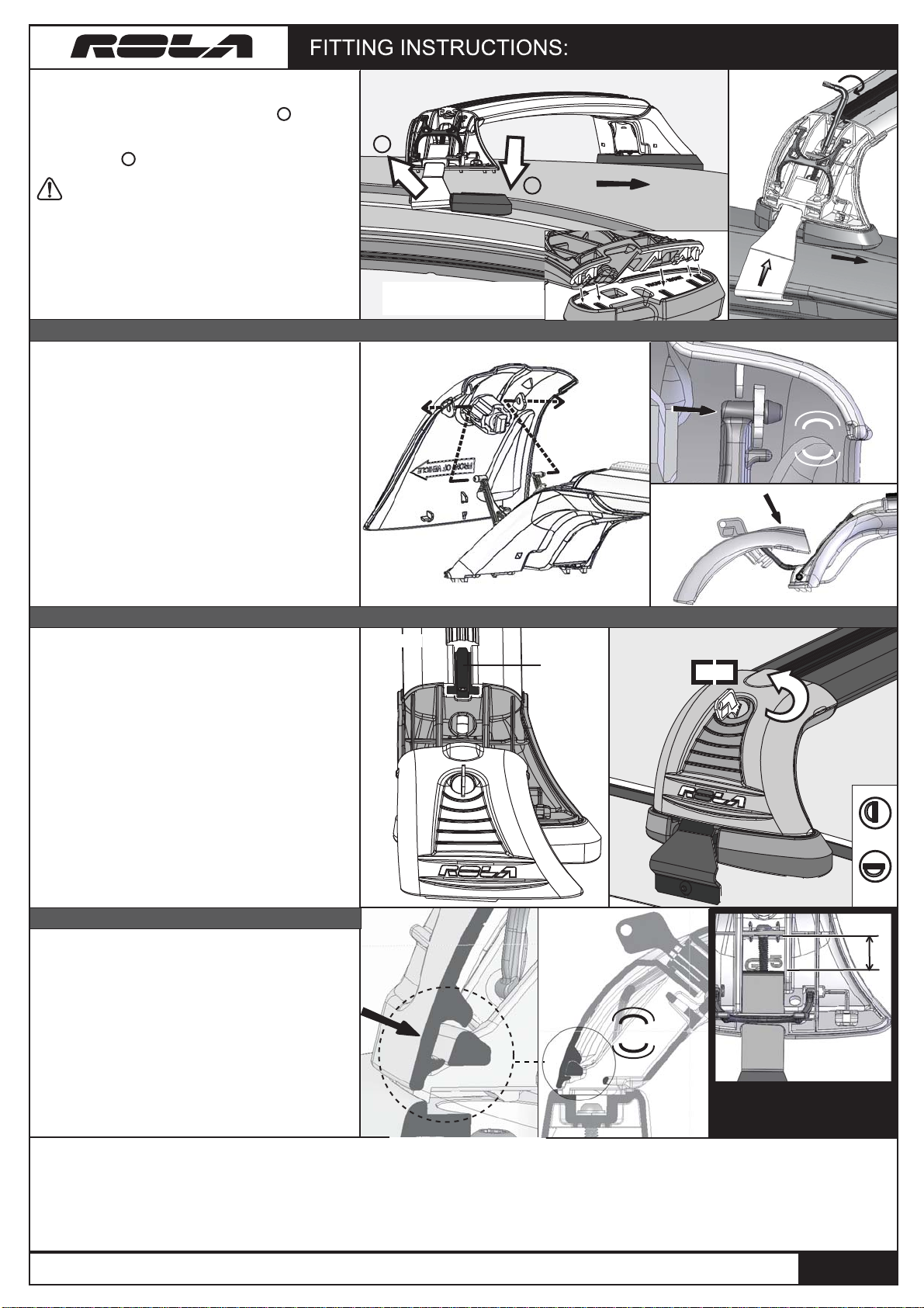
Front of vehicle
Rear Right End Support Shown.
Fig 3a.
Fig 3c.
CLICK
Mounting Cover onto End Support Chassis
GTX REMOVABLE Series Roof Racks
Fig 2c.
PUSH
PULL
1
2
Ensure ‘hooks’ on the base of the
End Support are mated with the
corresponding holes in the pads.
Front of vehicle
CLICK
LOCK
Locking End Supports & Mounting Accessories
Mounting Cover onto End Support Chassis
Fig 4b.
Fig 4c. Fig 4d.
Fig 4a.
1
2
6. With one strap loosely mated around the door
return, hold the other strap in your fingers whilst flexing
it outwards of the roof body. (Refer to Step in Fig 2c.)
Next, proceed to pull the strap down over the roof body
and into its designated place around the door return.
(Refer to Step in Fig 2c.)
Ensure the protective rubber on the straps doesn’t
come away so as not to damage vehicle paint.
7. Using the Assembly ‘L’ Key supplied, tighten the bolt
to pull strap upwards against the vehicle’s door return
channel. (Fig 2d)
IMPORTANT: Please refer to Fig 5 at bottom of page for
Front and Rear Strap tightened state conditions.
TIP: Whilst tensioning the straps, alternate from left to right hand sides to
ensure even tention on both sides.
8. Locate ends of hinge with cover mount holes.
Flex hinge ends together and line up with cover
mount holes.
Push ends through holes until capped heads of
hinge have entirely pushed through (Fig 3a).
9. Ensure hinge has been mounted correctly
by pushing ends through until you hear an
audible ‘click’ (Fig 3b).
10. Fully extend cover away from End-Support.
Pivot cover on hinge whilst pushing top
downwards until cover is held fixed (Fig 3c).
Fig 2d.
13. Ensure ALL End Support covers are pushed
hard up against the End Support (Fig. 4c/4d).
You should hear an audible ‘click’ when cover is
fully engaged (Fig. 4d).
11. You are now ready to mount your
accessories, eg. Bike Carrier, Kayak carrier, etc.
utilising the ‘Global Channnel’ if applicable(Fig. 4a)
Be sure to cut the buffer strip to size to
completely cover the Global channel once your
accessory is fitted onto the crossbars.
12. Lock all 4 covers into place with key
provided (Fig. 4b). Remove key and store in a
safe place - eg. with car keys/glove box.
‘GLOBAL
CHANNEL’
access
For full warranty information, visit our website: www.rola.com.au
Locked
Unlocked
PRESS
PUSH
X
General Usage Information
Fig 5.
FRONT STRAP
(RIGHT & LEFT) DIST. (X) = 16mm
[]


