manuals.online logo
Brands
  1. Home
  2. •
  3. Brands
  4. •
  5. Roper Rhodes
  6. •
  7. Indoor Furnishing
  8. •
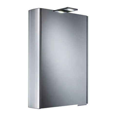
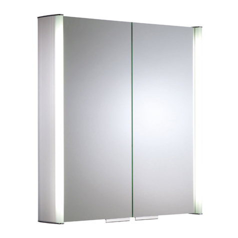
  9. Roper Rhodes Hyper MLE370 User manual

Roper Rhodes Hyper MLE370 User manual

Other Roper Rhodes Indoor Furnishing manuals

Roper Rhodes ASCENSION FEVER AS251 Parts list manual

Roper Rhodes

Roper Rhodes ASCENSION FEVER AS251 Parts list manual

Roper Rhodes PLATEAU AS515ALIL User manual

Roper Rhodes

Roper Rhodes PLATEAU AS515ALIL User manual

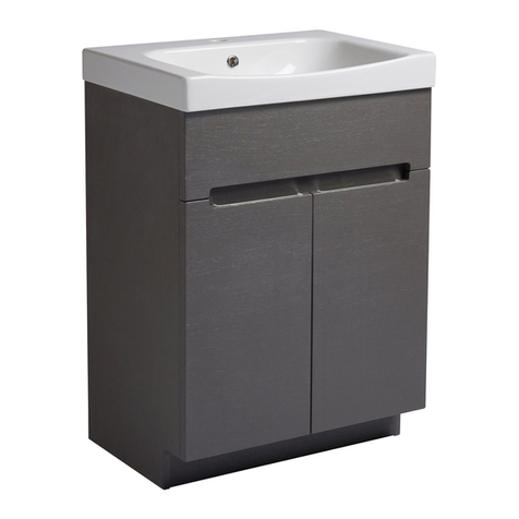
Roper Rhodes Diverge Floor Mounted Unit User manual

Roper Rhodes

Roper Rhodes Diverge Floor Mounted Unit User manual

Roper Rhodes ENVY 700 User manual

Roper Rhodes

Roper Rhodes ENVY 700 User manual

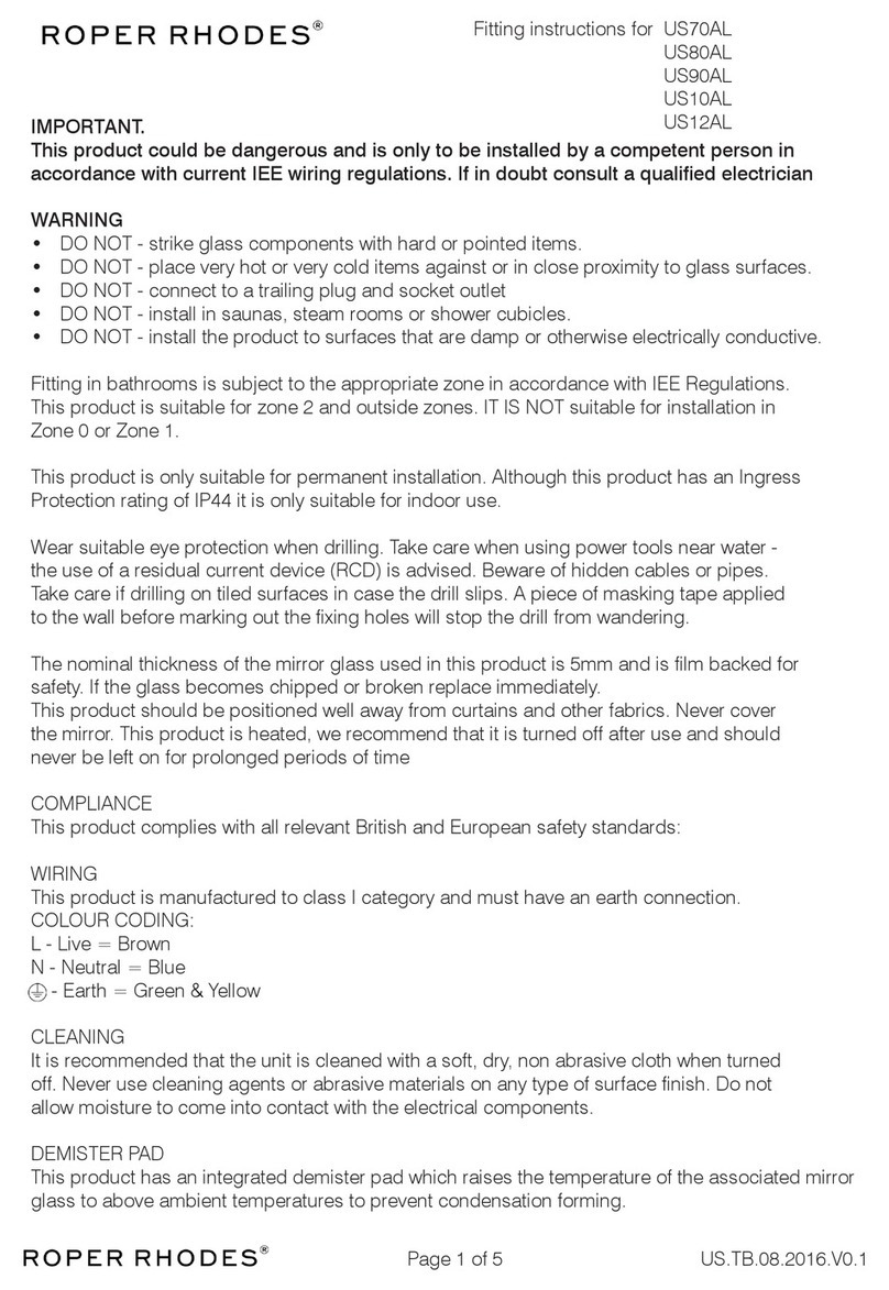
Roper Rhodes US70AL User manual

Roper Rhodes

Roper Rhodes US70AL User manual

Roper Rhodes Hampton HAM400FC User manual

Roper Rhodes

Roper Rhodes Hampton HAM400FC User manual

Roper Rhodes FR60RW Instruction sheet

Roper Rhodes

Roper Rhodes FR60RW Instruction sheet

Roper Rhodes MLE420 Parts list manual

Roper Rhodes

Roper Rhodes MLE420 Parts list manual

Roper Rhodes SYC050 User manual

Roper Rhodes

Roper Rhodes SYC050 User manual

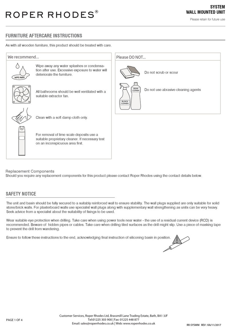
Roper Rhodes SYSTEM Series User manual

Roper Rhodes

Roper Rhodes SYSTEM Series User manual

Roper Rhodes EMINENCE EM70RAL User manual

Roper Rhodes

Roper Rhodes EMINENCE EM70RAL User manual

Roper Rhodes FO70AL Parts list manual

Roper Rhodes

Roper Rhodes FO70AL Parts list manual

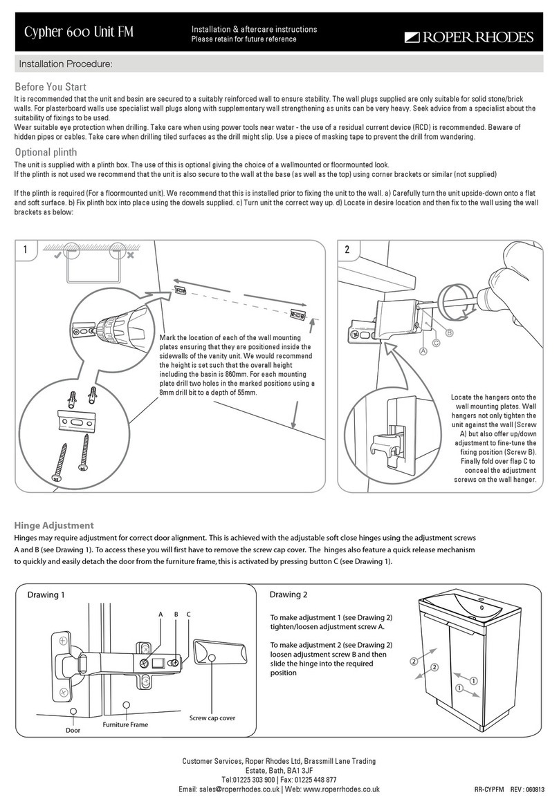
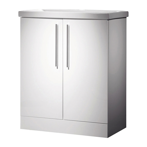
Roper Rhodes Cypher 600 Unit FM Parts list manual

Roper Rhodes

Roper Rhodes Cypher 600 Unit FM Parts list manual

Roper Rhodes HAMPTON User manual

Roper Rhodes

Roper Rhodes HAMPTON User manual

Popular Indoor Furnishing manuals by other brands

Regency LWMS3015 Assembly instructions

Regency

Regency LWMS3015 Assembly instructions

Furniture of America CM7751C Assembly instructions

Furniture of America

Furniture of America CM7751C Assembly instructions

Safavieh Furniture Estella CNS5731 manual

Safavieh Furniture

Safavieh Furniture Estella CNS5731 manual

PLACES OF STYLE Ovalfuss Assembly instruction

PLACES OF STYLE

PLACES OF STYLE Ovalfuss Assembly instruction

Trasman 1138 Bo1 Assembly manual

Trasman

Trasman 1138 Bo1 Assembly manual

Costway JV10856 manual

Costway

Costway JV10856 manual

moss DESIGN Caisson Credenza Assembly instructions

moss DESIGN

moss DESIGN Caisson Credenza Assembly instructions

Aquaglide FULL DECK 15.0 owner's manual

Aquaglide

Aquaglide FULL DECK 15.0 owner's manual

AREBOS AR-HE-SW30 user manual

AREBOS

AREBOS AR-HE-SW30 user manual

Till-Hilft Fulda 87005.330 Assembly instructions

Till-Hilft

Till-Hilft Fulda 87005.330 Assembly instructions

Twoey Outside 2010 quick start guide

Twoey Outside

Twoey Outside 2010 quick start guide

Hettich Easys 200 operating instructions

Hettich

Hettich Easys 200 operating instructions

The bedboss RELAX 404 Series owner's manual

The bedboss

The bedboss RELAX 404 Series owner's manual

Oeseder Möbelindustrie Bern 991 720 Assembly instructions

Oeseder Möbelindustrie

Oeseder Möbelindustrie Bern 991 720 Assembly instructions

Costway HW68469 user manual

Costway

Costway HW68469 user manual

Next ALIX A27743 Assembly instructions

Next

Next ALIX A27743 Assembly instructions

BROSA Hans Assembly guide

BROSA

BROSA Hans Assembly guide

Prodigg MINIKA PBA015T-FUR installation manual

Prodigg

Prodigg MINIKA PBA015T-FUR installation manual

manuals.online logo
manuals.online logoBrands
  • About & Mission
  • Contact us
  • Privacy Policy
  • Terms and Conditions

Copyright 2025 Manuals.Online. All Rights Reserved.

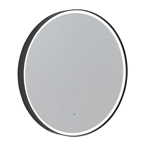
Installation Instructions for Hyper LED Mirror
RR.KH.LEDM.06.10
Roper Rhodes Ltd, Brassmill Lane Trading Estate, Bath, BA1 3JF |Tel: 01225 334148 |waww.roperrhodes.co.uk
Please read carefully before you start and retain for future reference
Hyper
MLE370
22
2
2
OUTSIDE
ZONES
Z
O
N
E
2
Z
O
N
E
1
0.75m
2.25m
3.0m
0.6m
0.6m
0.6m
0.75m
IEE BATHROOM ZONES DIAGRAM
IMPORTANT
MIRROR LOCATION
SAFETY INSTRUCTIONS
(Applicable to UK Installations only)
All fittings must be installed by a competent person, in accordance
with current IEE wiring regulations. If in doubt, consult a qualified
electrician.
IMPORTANT
Always switch off the electrical supply at the mains during
installation and maintenance. It is recommended that the fuse is
withdrawn or the circuit breaker is switched off for the necessary
circuit before installation commences.
The product must be mounted a minimum of 150mm from an
adjacent wall or obstruction to ensure correct function of the
infrared sensor. The sensor can be repositioned if required. See
overleaf for details.
Fitting in Bathrooms is subject to the appropriate location (See
Diagram). Refer to IEE Regulations. This product is suitable for
Zones 2 and outside zones. It IS NOT suitable for installation in
Zone 0 or Zone 1. It is also not suitable for installation in Saunas,
Steam Rooms or Shower Cubicles.
This product is only suitable for permanent installation. DO NOT
connect to a trailing plug and socket outlet.
Although this product has an Ingress Protection rating of IP44, it is
only suitable for indoor use.
Do not attach the product to surfaces that are damp or otherwise
electrically conductive.
The product should be positioned well away from curtains and other
fabrics. Never cover the mirror.
Always ensure that the correct bulb is used and that the maximum
bulb rating is not exceeded.
This product is heated, we recommend that it is turned off after use
and should never be left on for prolonged periods of time.
CARE & SAFETY
REMEMBER
Wear suitable eye protection when drilling. Take care when using
power tools near water - the use of a residual current device (RCD)
is advised. Beware of hidden cables or pipes. Take care if drilling
on tiled surfaces in case the drill slips. A piece of masking tape
applied to the wall before marking out the fixing holes will stop the
drill from wandering.
WARNINGS
Do not strike glass components with hard or pointed items. Do not
place very hot or very cold items against or in close proximity to
glass surfaces unless an adequately thick insulation material is
used to prevent such items coming in contact with the glass.
The nominal thickness of the mirror glass used in this product is
8mm and is film backed for safety. If the glass becomes chipped or
broken, replace immediately. For details on replacement glass and
other components contact customer services at the address below.
THE MAXIMUM EVENLY DISTRIBUTED SHELF LOAD FOR THIS
PRODUCT IS 6KG. EXCEEDING THIS LOAD COULD BE DANGEROUS
AND MAY CAUSE DAMAGE TO THE PRODUCT. AVOID SHOCK
LOADING.
This product could be dangerous and installation is only to be
carried out by a competent person.
It is recommended that the unit is cleaned with a soft dry cloth
when turned off. Never use cleaning agents or abrasive materials
on any type of surface finish. Do not allow moisture to come into
contact with the lamp.
COMPLIANCE
This product complies with the following Electrical Safety
Standards:
EN 55015:2001; BS EN 60598-1: 2004, AMD:2001, AMD:2003; BS EN
60598-2-1: 1989. EN 60529: 1992 & A1, A2, A3.
REPLACING LED’S
In the unlikely event that the LED light strip should fail please
contact customer services for a replacement part at the address
shown.
WARNING
Disconnect the unit from the mains power supply before attempting
to replace a light strip. Remove the mirror glass from the body by
removing the screws and washers. Disconnect the heated mirror
pad and LED light strips and place the mirror face down on clean
soft surface.
The LED strips can be removed by sliding them along the mounting
plate, the replacement should then be pushed onto the mounting
plate until it clicks securely into place. Reconnect the the heated
pad and LED light strips. Reposition the mirror glass on the body
and secure with the screws and washers previously removed.
All fittings must be installed by a competent person, in
accordance with current IEE wiring regulations. If in doubt,
consult a qualified electrician.
150mm
Minimum distance
Infrared sensor
520mm
760mm
170mm
Installation Instructions for Hyper LED Mirror
RR.KH.LEDM.06.10
Roper Rhodes Ltd, Brassmill Lane Trading Estate, Bath, BA1 3JF |Tel: 01225 334148 |waww.roperrhodes.co.uk
Please read carefully before you start and retain for future reference
Heated pad power
connector
4x wall plugs 4x screws
1
4
The wall surface must be of suitable strength and construction.
NOTE: Wall plugs provided are suitable for Stone or Brick walls. For other wall types use
appropriate wall plugs. If in doubt consult an expert.
To ensure correct operation of the infrared sensor the mirror must be mounted so that
there is a minimum of 150mm clearance immediately adjacent to the sensor. Where this is
not possible the sensor can be relocated by drilling a 12mm hole in the mirror body (not
glass) in the desired location, unscrewing the plastic nut from the sensor (see diagram 3)
and reinstalling it in the new hole. The old hole must be blocked using the spare grommet
supplied.
1) Carefully remove the mirror by unfastening the securing screws on the sides of the
mirror and separate from the main body. Place the mirror, screws and washers in a safe
place for now. The heated mirror pad and the LED light strips should be disconnected by
separating the plugs.
2) Mark the desired height of the mirror and draw a horizontal line on the wall (using a
spirit level) which corresponds with the height of the top holes in the back of the mirror
body.
! IF IN DOUBT CONSULT YOUR ELECTRICIAN !
IMPORTANT: Loose connections can lead to over heating. Excessive temperatures may
lead to scorching of the plastic components, and in extreme cases may even melt.
Charring of components is always a consequence of faulty installation or maintenance,
and any claims are excluded from the warranty.
4) Reconnect the heated mirror pad and the LED light strips.
5) Replace the mirror over the front of the body, aligning the holes in the brackets with the
screw holes. Make sure that the glass fits completely flat on the face of the body. Secure
with the screws and washers removed in stage 1.
6) Turn back on the electrical supply so that your LED mirror is operational.
7) To switch the mirror on or off move your hand past the Infrared sensor (must be within
6cm), the heated pad is turned on when the LED lights are illuminated. We recommend the
product is turned off after use.
Strip wires to a suitable
length. DO NOT connect
to a plug & socket outlet.
Colour Coding:
L - Live = Brown
N - Neutral = Blue
- Earth = Green & Yellow
PROCEDURE
Holding the mirror body in place on the horizontal line, mark off all 4 holes in the back of
the mirror body. Also mark off where the electrical supply cable must be placed in case
this needs to be chased out locally for the installation. Place the mirror body to one side
and drill the holes as necessary for the wall plugs. Insert the wall plugs and screw the
mirror body in position having fed the power supply cable through the rubber grommet in
the mirror body. Make sure that all screws are secure.
3) Ensure that the electrical supply is turned off at the mains. Remove the connection box
cover inside the mirror body and the cable clamp to allow the electrical connections to be
made as follows:
THIS PRODUCT IS MANUFACTURED TO CLASS I
CATEGORY AND MUST HAVE AN EARTH CONNECTION.
Strip the mains PVC supply cable as necessary. Thread the power supply through the
rubber grommet on the switch box and make the necessary connections in accordance
with the current IEE Regulations. Firmly tighten all terminal connections. Make sure the
cable clamp is replaced and tightened and the connection box cover is securely screwed
back on.
Parts Inluded
1x grommet
1x mirror
LED power connector
Mirror glass
Cable clamp
Connection box cover & screw
Power supply cable
Body
3
2
N.B. Ensure connection box cover is securely fastened
in place after connections have been made
LN
Output Wires
Live Terminal
Connection
Earth Terminal
Connection
Neutral Terminal
Connection
Cable Clamp
To remove and relocate sensor
(if required)
IR Sensor switch
Shaver transformer
Shaver socket
The shaver socket is always active &
able to charge whether light is on/off
Plastic nut
Infrared sensor
Shaver socket